EP0231069B1 - Kriechgangvorgelege für Traktorgetriebe - Google Patents
Kriechgangvorgelege für Traktorgetriebe Download PDFInfo
- Publication number
- EP0231069B1 EP0231069B1 EP19870300234 EP87300234A EP0231069B1 EP 0231069 B1 EP0231069 B1 EP 0231069B1 EP 19870300234 EP19870300234 EP 19870300234 EP 87300234 A EP87300234 A EP 87300234A EP 0231069 B1 EP0231069 B1 EP 0231069B1
- Authority
- EP
- European Patent Office
- Prior art keywords
- clutch
- shaft
- creeper
- transmission
- speed
- Prior art date
- Legal status (The legal status is an assumption and is not a legal conclusion. Google has not performed a legal analysis and makes no representation as to the accuracy of the status listed.)
- Expired
Links
- 230000005540 biological transmission Effects 0.000 title claims description 48
- 241000219098 Parthenocissus Species 0.000 title claims description 42
- 230000009467 reduction Effects 0.000 claims description 28
- 230000009977 dual effect Effects 0.000 description 4
- 239000012530 fluid Substances 0.000 description 4
- 230000007935 neutral effect Effects 0.000 description 3
- 230000003321 amplification Effects 0.000 description 1
- 230000006835 compression Effects 0.000 description 1
- 238000007906 compression Methods 0.000 description 1
- 238000003199 nucleic acid amplification method Methods 0.000 description 1
- 238000007789 sealing Methods 0.000 description 1
Images
Classifications
-
- F—MECHANICAL ENGINEERING; LIGHTING; HEATING; WEAPONS; BLASTING
- F16—ENGINEERING ELEMENTS AND UNITS; GENERAL MEASURES FOR PRODUCING AND MAINTAINING EFFECTIVE FUNCTIONING OF MACHINES OR INSTALLATIONS; THERMAL INSULATION IN GENERAL
- F16H—GEARING
- F16H37/00—Combinations of mechanical gearings, not provided for in groups F16H1/00 - F16H35/00
- F16H37/02—Combinations of mechanical gearings, not provided for in groups F16H1/00 - F16H35/00 comprising essentially only toothed or friction gearings
- F16H37/04—Combinations of toothed gearings only
- F16H37/042—Combinations of toothed gearings only change gear transmissions in group arrangement
- F16H37/043—Combinations of toothed gearings only change gear transmissions in group arrangement without gears having orbital motion
-
- F—MECHANICAL ENGINEERING; LIGHTING; HEATING; WEAPONS; BLASTING
- F16—ENGINEERING ELEMENTS AND UNITS; GENERAL MEASURES FOR PRODUCING AND MAINTAINING EFFECTIVE FUNCTIONING OF MACHINES OR INSTALLATIONS; THERMAL INSULATION IN GENERAL
- F16H—GEARING
- F16H3/00—Toothed gearings for conveying rotary motion with variable gear ratio or for reversing rotary motion
- F16H3/02—Toothed gearings for conveying rotary motion with variable gear ratio or for reversing rotary motion without gears having orbital motion
- F16H3/08—Toothed gearings for conveying rotary motion with variable gear ratio or for reversing rotary motion without gears having orbital motion exclusively or essentially with continuously meshing gears, that can be disengaged from their shafts
Definitions
- This invention relates to a multiple speed ratio trasctor transmission. More particularly, the invention pertains to a dual power mechanism and to a creeper speed mechanism for producing an extraordinarily large gear ratio.
- Tractor transmissions are designed to produce a larger number of gear ratios within a mechanism located between the engine and the final drive or differential mechanism.
- the gear arrangement of the transmission may produce a gear reduction or ratio of approximately 9:l between the speed of the transmission output and the engine speed.
- the torque delivery path of a tractor transmission includes a creeper speed mechanism located behind the transmission gear arrangement and before the differential mechanism.
- the creeper speed mechanism produces an additional speed reduction of about 5:l between the output of the transmission gear arrangement and the output of the creeper speed mechanism. This combination of speed ratios will produce an overall speed reduction of approximately 45:l between the output of the creeper speed mechanism and the engine.
- the creeper speed mechanism is an additional gear mechanism located in conventional tractor drivelines at the rear of the transmission, its presence increases the overall length of the transmission. It is preferable that the creeper speed mechanism be as short as possible so that the transmission can be fitted within the smallest space possible. Yet to produce a sufficiently large speed reduction between the engine and the transmission output required by tractor operators for certain conditions, the creeper speed mechanism must include several speed reductions which necessarily increase the space required by the mechanism.
- DE-A-2,410,164 discloses a change gear transmission which comprises a group transmission that precedes a main control group and in which the input shaft is driven by a driving engine through the intervention of an engageable and disengageable driving clutch and in which said change gear transmission includes two control stages, each of which is adapted to be engaged and disengaged by a friction clutch.
- a tractor transmission comprising a first shaft which is clutched to the engine, a transmission input shaft, creeper speed reduction means, first and second clutch means for selectively, driveably connecting the first shaft to the respective outputs of the first and second clutch means and speed reduction means driveably connected to the output of the first and second clutch means, characterised in that the creeper speed reduction means is driveably connected to the first speed reduction means, and the transmission further includes means for selectively, driveably connecting the creeper speed reduction means to the transmission input shaft.
- the clutches are engaged selectively by connecting a source of pressurized fluid to the respective clutch pistons.
- a hydraulic valve opens communication between one of the clutches and the pressurized fluid source. If a higher speed ratio is required, movement of the shift selector to the higher gear ratio closes the connection to the first clutch and communicates the fluid pressure source to the second clutch.
- the first speed reduction means includes a countershaft rotatably mounted on the transmission casing parallel to the axis of the shaft that is connected to the engine.
- the counter shaft carries two pinions which turn with the countershaft and are engaged respectively with the output component of the first and second clutches.
- a third pinion carried on the countershaft is continuously engaged with a creeper gear carried rotatably on the transmission input shaft. This pinion and the creeper gear produce a speed reduction between the countershaft and the input shaft.
- the connecting means includes a coupler, slideably mounted on the input shaft, and which moves between a position where the coupler is connected to the creeper gear and another position where the coupler is connected to the output component of one of the clutches.
- the coupler is continuously, driveably connected to the transmission input shaft. Therefore, movement of the coupler connects either the creeper speed gear or the output component of the clutch to the input shaft.
- the gears that are formed integrally with the clutch outputs and the pinions with which they are engaged on the countershaft are sized to produce a torque amplification and speed reduction between the shaft that is connected to the engine and the countershaft.
- the creeper gear and the pinion with which it is engaged on the countershaft are sized to produce an additional speed reduction and torque application between the countershaft and the transmission input shaft.
- the output of one of the hydraulically actuated clutches is connected by the coupler directly to the transmission input shaft. When the other hydraulic clutch is actuated and the coupler is positioned other than for creeper operation, the transmission input shaft is overdriven with respect to the engine shaft.
- the output of the first clutch drives a pinion on the countershaft, which produce a speed reduction.
- the connection that the coupler makes with the creeper gear produces a second speed reduction between the speed of the countershaft and the transmission input shaft.
- the transmission input shaft is either over-driven with respect to the engine speed or it is directly connected to the engine. Otherwise, when the coupler is positioned for creeper speed operation, the two speed ratios that result from selective engagement of the first and second clutches and the speed reduction associated with the creeper speed mechanism product two larger speed reductions between the engine and the transmission input shaft.
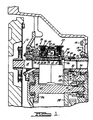
- Figure l is a cross section through a plane that contains the axes of the engine shaft and transmission input shaft at the fron portion of a tractor transmission according to this invention.
- the output shaft of an engine is driveably connected to the power take off shaft l0 of a tractor transmission through a neutral clutch l2.
- the transmission is housed in a casing l4 comprising several segments which are joined at bolted connections l6.
- a first hydraulically actuated disc clutch assembly driveably connects shaft l0 to first and second output components of the clutches.
- shaft l0 is connected to clutch output components 28 or 30, respectively.
- the input element 24 of the clutches is joined at a spline 26 to shaft l0; their output components 28, 30 are rotatably supported on the shaft and are formed integrally with gears 32, 34, which are in continuous meshing engagement with pinions 36, 38.
- These pinions are rotatably supported on countershaft 40, which is substantially parallel to the axis of shaft l0.
- Clutch 20 includes a hydraulic cylinder 42 driveably connected to the input component 24, a piston 44, a first set of clutch discs 46 splined to the cylinder 42, a second set of clutch discs 48 splined to output component 28, a spring retainer 52, a coiled compression spring 50 fitted between the spring retainer and the piston, seals 53, 54 for hydraulically sealing the pressurized portion of the cylinder from the unpressurized portion, and a bearing 56 for rotatably supporting the output component on shaft l0.
- the hydraulic system of the transmission connects a source of high pressure hydraulic fluid through a hydraulic passage 58 to the interior of the cylinder.
- the low pressure portion of the cylinder is connected by passage 60 to a reservoir or sump at atmospheric pressure.
- Clutch 22 includes corresponding components to those described with respect to clutch 20 and functions in the same way as clutch 20 when its cylinder is pressurized through passage 62 from the source of hydraulic pressure. Clutches 20 and 22 are operated alternately; they are not fully engaged concurrent during any of the forward drive, reverse drive or creeper speed ratio conditions.
- clutch 20 When clutch 20 is energized, its cylinder is pressurized and the clutch discs 46, splined to the cylinder, are forced into frictional contact with discs 48, splined on the output component 28.
- the input component 24 When the pressure in the cylinder rises sufficiently, the input component 24 is driveably connected to the output component 28 and driveably connects shaft l0 and gear 32.
- clutch 22 when clutch 22 is pressurized, a driveable connection is made through engagement of the corresponding disc sets between shaft l0 and gear 34.
- Pinion 36 is formed integrally with countershaft 40, and pinions 38, 66 are connected by spline 64 to the countershaft. Pinion 66 is in continuous engagement with creeper gear 68, which is rotatably mounted by bearing 70 on the outer surface of the transmission input shaft 72. Shaft l0, the power takeoff shaft, extends from the front of the transmission to the rear through a bore in shaft 72.
- the gear wheel on which creeper gear 68 is formed includes a set of dog teeth 74 engageable by a corresponding set of dog teeth 76 located on the circumference of a coupler 78.
- a set of splines 80 Located at the forward end of the input shaft is a set of splines 80, with which the splines 82 on the inside diameter of coupler 78 are continuously engaged.
- a set of dog teeth 84 Located at the rearward end of the output component 30 of clutch 22 is a set of dog teeth 84, which is engageable by the splines 82 of the coupler.
- the coupler is mounted for axial sliding movement on the input shaft and remains continuously engaged with the input shaft.
- coupler 78 When coupler 78 is moved rearward from the neutral position shown in the figure, it is brought into driveable engagement with creeper gear 68. When the coupler is moved forward from the neutral position, it is brought into driveable engagement with the output component of clutch 22.
- the device embodying to this invention will produce, through selective operation of clutches 20 and 22, a dual power input between the engine shaft and the input shaft 72 of the transmission.
- clutch 20 When clutch 20 is engaged, clutch 22 is disengaged, coupler 78 is moved forward to its normal position, and output shaft 72 is overdriven with respect to the engine, i.e., the speed of shaft 72 is greater than the engine speed.
- the clutches and coupler When the clutches and coupler are so disposed, power is transmitted from power takeoff shaft l0 through clutch 20, gear 32, pinion 36, spline 64, pinion 38, gear 34 and coupler 78 to the input shaft 72.
- the relative sizes of the meshing gears and pinions 32, 40 and 38, 34 cause input shaft 72 to be overdriven approximately l.6 times the speed of shaft l0.
- clutch 20 When clutch 22 is engaged, clutch 20 is disengaged and coupler 78 is moved forward to its normal position, shaft l0 is connected to the input shaft 72 through the torque delivery path that includes spline 26, the discs of clutch 22, output component 30 and coupler 78. This torque delivery path causes the input shaft 72 to be driven at the speed of shaft l0.
- the dual power input mechanism connects the engine through clutches 20 and 22 either directly to the transmission input or through the speed reduction gearset to the transmission input.
- the creeper mechanism according to this invention has the capacity to produce a speed reduction between the engine and the transmission input by moving the coupler rearward from the position of engagement with the output of clutch 22 and into engagement with creeper gear 68. When this is done, selective engagement of clutches 20 and 22 produces two ratios of the speed of the input shaft with respect to the engine shaft.
- the creeper speed mechanism produces the higher creeper speed ratio or the lower torque ratio when clutch 20 is engaged, clutch 22 is disengaged and coupler 78 is moved rearward to the creeper speed position.
- the torque delivery path between shaft l0 and input shaft 72 includes clutch 20, gear 32, pinion 36, creeper pinion 66, creeper gear 68, dog teeth 74, 76 and coupler 78.
- the creeper speed mechanism produces the lower creeper speed ratio or the higher torque ratio when clutch 20 is disengaged, clutch 22 is engaged and coupler 78 is moved rearward to bring its dog teeth 76 into engagement with the the dog teeth 74 on the creeper gear wheel 68.
- the torque delivery path that connects shaft l0 to shaft 72 includes clutch 22, gear 34, pinion 38, creeper pinion 66, creeper gear 68, dog teeth 74, 76, and coupler 78.
Landscapes
- Engineering & Computer Science (AREA)
- General Engineering & Computer Science (AREA)
- Mechanical Engineering (AREA)
- Structure Of Transmissions (AREA)
- Arrangement Of Transmissions (AREA)
Claims (4)
- Zugmaschinengetriebe mit einer mit dem Motor verkuppelten ersten Welle (10), einer Getriebeeingangswelle (72), einem Kriechgangverringerungsmittel (68), einem ersten und zweiten Kupplungsmittel (20, 22), um die erste Welle (10) gezielt mit den jeweiligen Ausgängen des ersten und zweiten Kupplungsmittels (20, 22) in Antriebsverbindung zu bringen, und mit einem ersten Drehzahlverringerungsmittel (36, 38, 40, 66), das mit dem Ausgang des ersten und zweiten Kupplungsmittels (20, 22) in Antriebsverbindung steht, dadurch gekennzeichnet, daß das Kriechgangverringerungsmittel (68) mit dem ersten Drehzahlverringerungsmittel (36, 38, 40, 66) in Antriebsverbindung steht und das Getriebe weiterhin ein Mittel (78) einschließt, um das Kriechgangverringerungsmittel (68) gezielt mit der Getriebeeingangswelle (72) in Antriebsverbindung zu bringen.
- Zugmaschinengetriebe nach Anspruch 1, bei dem das Verbindungsmittel (78) den Ausgang des zweiten Kupplungsmittels (22) gezielt mit der Getriebeeingangswelle (72) in Antriebsverbindung bringt.
- Zugmaschinengetriebe nach Anspruch 1 oder 2, bei dem das erste Drehzahlverringerungsmittel (36, 38, 40, 66) eine Nebenwelle (40) einschließt, die rotationsmäßig parallel zur ersten Welle (10) angeordnet ist und ein erstes Ritzel (36), das mit dem Ausgang des ersten Kupplungsmittels (20) kämmt, und ein zweites Ritzel (66) trägt, das mit dem Kriechgangverringerungsmittel (68) in Antriebsverbindung steht, wobei jenes erste und zweite Ritzel (36, 66) rotationsmäßig an der Nebenwelle (40) befestigt ist.
- Zugmaschinengetriebe nach Anspruch 3, bei dem das erste Drehzahlverringerungsmittel (36, 38, 40, 66) weiterhin ein drittes Ritzel (38) auf der Nebenwelle (40) einschließt, das mit dem Ausgang des zweiten Kupplungsmittels (22) kämmt und mit dem zweiten Ritzel (66) in Antriebsverbindung steht.
Applications Claiming Priority (2)
| Application Number | Priority Date | Filing Date | Title |
|---|---|---|---|
| US81850986A | 1986-01-13 | 1986-01-13 | |
| US818509 | 1986-01-13 |
Publications (2)
| Publication Number | Publication Date |
|---|---|
| EP0231069A1 EP0231069A1 (de) | 1987-08-05 |
| EP0231069B1 true EP0231069B1 (de) | 1991-04-03 |
Family
ID=25225707
Family Applications (1)
| Application Number | Title | Priority Date | Filing Date |
|---|---|---|---|
| EP19870300234 Expired EP0231069B1 (de) | 1986-01-13 | 1987-01-12 | Kriechgangvorgelege für Traktorgetriebe |
Country Status (2)
| Country | Link |
|---|---|
| EP (1) | EP0231069B1 (de) |
| DE (1) | DE3768970D1 (de) |
Families Citing this family (3)
| Publication number | Priority date | Publication date | Assignee | Title |
|---|---|---|---|---|
| IT1211425B (it) * | 1987-10-26 | 1989-10-18 | Same Spa | Gruppo di cambio di velocita in power shift per trattori |
| DE102005021674A1 (de) | 2005-05-11 | 2006-12-14 | Bayerische Motoren Werke Ag | Fahrzeuggetriebe mit sechs Vorwärtsgängen für normalen Fahrbetrieb, sowie einem Kriech- bzw. Berganfahrgang und einem Rückwärtsgang |
| DE102009026710A1 (de) * | 2009-06-04 | 2010-12-09 | Zf Friedrichshafen Ag | Anordnung mit zumindest einer Klauenkupplung |
Family Cites Families (4)
| Publication number | Priority date | Publication date | Assignee | Title |
|---|---|---|---|---|
| DE1950914C3 (de) * | 1969-10-09 | 1982-11-11 | Klöckner-Humboldt-Deutz AG, 5000 Köln | Schaltvorrichtung zum Schalten eines mehrstufigen, über eine Schalttrennkupplung angetriebenen Zahnräderwechselgetriebes, insbesondere für Ackerschlepper |
| US3906817A (en) * | 1973-12-17 | 1975-09-23 | Allis Chalmers | Multiple speed transmission |
| DE2410164C2 (de) * | 1974-03-02 | 1984-07-26 | Klöckner-Humboldt-Deutz AG, 5000 Köln | Zahnräderwechselgetriebe in Gruppenbauart |
| AU528214B2 (en) * | 1979-11-13 | 1983-04-21 | Kubota Ltd. | Vehicle transmission drive system |
-
1987
- 1987-01-12 EP EP19870300234 patent/EP0231069B1/de not_active Expired
- 1987-01-12 DE DE8787300234T patent/DE3768970D1/de not_active Expired - Lifetime
Also Published As
| Publication number | Publication date |
|---|---|
| DE3768970D1 (de) | 1991-05-08 |
| EP0231069A1 (de) | 1987-08-05 |
Similar Documents
| Publication | Publication Date | Title |
|---|---|---|
| US3906817A (en) | Multiple speed transmission | |
| US4458557A (en) | Four-wheel drive transfer apparatus for automobile's automatic transmission | |
| CA1302736C (en) | Countershaft transmission | |
| US4275608A (en) | Gearbox for an agricultural tractor | |
| US4676116A (en) | Countershaft transmission | |
| US4570503A (en) | Countershaft transmission | |
| US5525115A (en) | Mechanical transmission for drive wheels, especially for mobile work machines | |
| US6360623B1 (en) | Transmission system in working vehicles | |
| US20020165060A1 (en) | Continuously variable transmission | |
| US4660425A (en) | Countershaft transmission auxiliary drive mechanism | |
| US2972901A (en) | Forward and reverse reduction transmission | |
| US5443426A (en) | Transfer case with integrated planetary gear assembly and "on-demand" four-wheel drive | |
| US4459872A (en) | Clutch actuator | |
| US4686869A (en) | Ratio change gear speed synchronizing in a tractor transmission | |
| EP0282491B1 (de) | Vorgelegewellengetriebe | |
| EP0066381A1 (de) | Getriebe für Kraftfahrzeuge | |
| US20050277509A1 (en) | Transfer case with forward hydraulic clutch | |
| US4532827A (en) | Dual power transmission for tractor vehicles | |
| US4706519A (en) | Creeper speed actuator for a tractor transmission | |
| US4856375A (en) | Mechanism for synchronized shifting of a transmission using couplers | |
| US3357276A (en) | Transmission and its control | |
| US6364045B1 (en) | Front wheel drive clutch for tractors | |
| EP0231069B1 (de) | Kriechgangvorgelege für Traktorgetriebe | |
| US3964584A (en) | Speed-changing system with two fluid-actuated clutches | |
| US4074592A (en) | Direct drive transmission with hydraulically actuated forward and reverse clutches |
Legal Events
| Date | Code | Title | Description |
|---|---|---|---|
| PUAI | Public reference made under article 153(3) epc to a published international application that has entered the european phase |
Free format text: ORIGINAL CODE: 0009012 |
|
| AK | Designated contracting states |
Kind code of ref document: A1 Designated state(s): BE DE FR GB NL |
|
| 17P | Request for examination filed |
Effective date: 19880122 |
|
| 17Q | First examination report despatched |
Effective date: 19890425 |
|
| GRAA | (expected) grant |
Free format text: ORIGINAL CODE: 0009210 |
|
| AK | Designated contracting states |
Kind code of ref document: B1 Designated state(s): BE DE FR GB NL |
|
| PG25 | Lapsed in a contracting state [announced via postgrant information from national office to epo] |
Ref country code: NL Effective date: 19910403 Ref country code: BE Effective date: 19910403 |
|
| REF | Corresponds to: |
Ref document number: 3768970 Country of ref document: DE Date of ref document: 19910508 |
|
| ET | Fr: translation filed | ||
| NLV1 | Nl: lapsed or annulled due to failure to fulfill the requirements of art. 29p and 29m of the patents act | ||
| PLBE | No opposition filed within time limit |
Free format text: ORIGINAL CODE: 0009261 |
|
| STAA | Information on the status of an ep patent application or granted ep patent |
Free format text: STATUS: NO OPPOSITION FILED WITHIN TIME LIMIT |
|
| 26N | No opposition filed | ||
| REG | Reference to a national code |
Ref country code: GB Ref legal event code: 732 |
|
| REG | Reference to a national code |
Ref country code: FR Ref legal event code: TP |
|
| REG | Reference to a national code |
Ref country code: GB Ref legal event code: IF02 |
|
| REG | Reference to a national code |
Ref country code: FR Ref legal event code: CD |
|
| PGFP | Annual fee paid to national office [announced via postgrant information from national office to epo] |
Ref country code: GB Payment date: 20060103 Year of fee payment: 20 |
|
| PGFP | Annual fee paid to national office [announced via postgrant information from national office to epo] |
Ref country code: FR Payment date: 20060110 Year of fee payment: 20 |
|
| PGFP | Annual fee paid to national office [announced via postgrant information from national office to epo] |
Ref country code: DE Payment date: 20060131 Year of fee payment: 20 |
|
| PG25 | Lapsed in a contracting state [announced via postgrant information from national office to epo] |
Ref country code: GB Free format text: LAPSE BECAUSE OF EXPIRATION OF PROTECTION Effective date: 20070111 |
|
| REG | Reference to a national code |
Ref country code: GB Ref legal event code: PE20 |