EP0230986B1 - A method and an arrangement for the feeding of a material web - Google Patents
A method and an arrangement for the feeding of a material web Download PDFInfo
- Publication number
- EP0230986B1 EP0230986B1 EP87100839A EP87100839A EP0230986B1 EP 0230986 B1 EP0230986 B1 EP 0230986B1 EP 87100839 A EP87100839 A EP 87100839A EP 87100839 A EP87100839 A EP 87100839A EP 0230986 B1 EP0230986 B1 EP 0230986B1
- Authority
- EP
- European Patent Office
- Prior art keywords
- web
- material web
- arrangement
- feed
- processing device
- Prior art date
- Legal status (The legal status is an assumption and is not a legal conclusion. Google has not performed a legal analysis and makes no representation as to the accuracy of the status listed.)
- Expired - Lifetime
Links
Images
Classifications
-
- B—PERFORMING OPERATIONS; TRANSPORTING
- B65—CONVEYING; PACKING; STORING; HANDLING THIN OR FILAMENTARY MATERIAL
- B65B—MACHINES, APPARATUS OR DEVICES FOR, OR METHODS OF, PACKAGING ARTICLES OR MATERIALS; UNPACKING
- B65B61/00—Auxiliary devices, not otherwise provided for, for operating on sheets, blanks, webs, binding material, containers or packages
- B65B61/02—Auxiliary devices, not otherwise provided for, for operating on sheets, blanks, webs, binding material, containers or packages for perforating, scoring, slitting, or applying code or date marks on material prior to packaging
-
- B—PERFORMING OPERATIONS; TRANSPORTING
- B65—CONVEYING; PACKING; STORING; HANDLING THIN OR FILAMENTARY MATERIAL
- B65B—MACHINES, APPARATUS OR DEVICES FOR, OR METHODS OF, PACKAGING ARTICLES OR MATERIALS; UNPACKING
- B65B41/00—Supplying or feeding container-forming sheets or wrapping material
- B65B41/18—Registering sheets, blanks, or webs
-
- B—PERFORMING OPERATIONS; TRANSPORTING
- B65—CONVEYING; PACKING; STORING; HANDLING THIN OR FILAMENTARY MATERIAL
- B65H—HANDLING THIN OR FILAMENTARY MATERIAL, e.g. SHEETS, WEBS, CABLES
- B65H23/00—Registering, tensioning, smoothing or guiding webs
- B65H23/04—Registering, tensioning, smoothing or guiding webs longitudinally
Definitions
- the present invention relates to a method whereby in the stepwise feeding and processing of a material web provided with irregularities the web is stopped when one of said irregularities is in a predetermined position at a processing device, wherein the passage of the front edge of the actual irregularity is sensed at a predetermined distance before the processing device (see e.g. GB-A-2 074 122).
- the invention also relates to an arrangement for the stepwise feeding of a material web provided with irregularities and suitable for processing in register with the irregularities, wherein as seen in the feed direction of the web it comprises a sensing device and a processing device, the arrangement also comprising a forward driving device constituted by a driven feed cylinder connected as is the sensing device to a control unit and adapted to interrupt the feeding in a desired position after a starting signal from the sensing device (see e.g. GB-A-2 074 122).
- Packing containers of paper or plastic-coated paper are often manufactured from weblike packing material which is provided with crease lines, emptying openings, tearing directions or print before it is divided into individual sheets or blanks and is converted by folding and sealing to finished packing containers.
- the majority of the working operations which are performed on the material web have to be carried out in register, that is to say, the working operation has to be done in a predetermined position on the material web in relation to the results of working operations already carried out previously. This is well-known in the technique of packaging and is achieved in a number of different ways.
- openings When packing material webs are to be provided with cutouts, holes or the like which, for example, are to serve as pouring openings in the finished packing container, the pouring openings are punched out first at regular intervals in the weblike packing material. Thereafter some form of opening arrangement is applied which in its simplest form of realization may be constituted e.g. of a tear-off cover strip glued on over the prepunched pouring opening, so that the latter is closed in the desired manner. The application of the opening arrangements or cover strips hereby has to take place in register with the pouring openings.
- the processing can take place with very small margin in register with the actual irregularity of the web.
- any altered or faulty distances between the irregularities, extensions in the web or other similar faults will not affect the final result. Consequently an almost exact application can be carried out of e.g. cover strips over pouring openings which are placed irregularly in longitudinal direction of the material web.
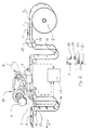
- Fig.1 shows in perspective the arrangement in accordance with the invention as it may be designed when it is used for application of opening arrangements to a packing material web provided with pouring openings.
- Fig.2 shows schematically the method in accordance with the invention.
- the arrangement in accordance with the invention is intended for the stepwise feeding of a material web 1 which is rolled off a material roll 2 supported so that it can freely rotate.
- the material web 1 is furnished with a number of irregularities 3 in the form of punched-out pouring openings which are provided at substantially equal distances along the length of the material web.
- irregularities is used in the description and claims to designate any form of marking (e.g. holes, slots, cutouts, indentations or printed markings) which diverge in registrable manner from the rest of the material web.
- the arrangement in accordance with the invention comprises, moreover, a sensing device 4 which is placed in such a position adjoining the material web 1 that the irregularities 3 or pouring openings pass directly under the sensing device 4.
- the sensing device may be constituted, for example, of a photocell which is directed towards the web and records the transition from the material web to the pouring opening.
- the pouring opening extends only through certain layers of the material (e.g. through a central carrier layer but not through plastic or aluminium foil layers), the sensing device records the transition from one material type to another.
- a processing device 5 which is placed adjoining the path of movement of the material web 1 and comprises a unit adapted to apply opening arrangements 6 in the form of cover strips onto the material web in register with the pouring openings.
- Opening arrangements 6 in the form of cover strips onto the material web in register with the pouring openings.
- a feed cylinder 7 which, together with a counter-cylinder 8 located underneath the material web, engages the material web and drives the same forward in the direction from right to left in Fig.1
- the feed cylinder 7 is connected via a driving shaft with a forward driving device 9 which is stepwise rotatable and lockable in a desired position.
- the forward driving device 9 is actuated via a power transmission 10 by means of a conventional electric motor 11.
- a pulse generator 12 On the driving shaft of the feed cylinder 7 is located a pulse generator 12 which like the forward driving device 9 and the sensing device 4 is connected electrically to a control unit 13.
- the arrangement in accordance with the invention comprises a number of guide rollers 14 which, together with guide rails and other guide elements, not shown, guide the packing material web through the unit. Furthermore, a driving cylinder 15 is present for the unrolling of the material web 1 off the material roll 2 timed so, that the intermittent driving forward of the material web through the arrangement in accordance with the invention with the help of the feed cylinder 7 is not affected by the inertia of the material roll 2.
- the part of the material web which is being processed by the arrangement in accordance with the invention is isolated from remaining parts of the material web by means of two material loops 16, the length of which is sensed mechanically or by means of photocells not shown and controls the feed of material web before and after the isolated part of the web. This too is conventional and well-known to those versed in the art and, therefore, will not be described in more detail.
- the sensing device 4 is located a little distance in front of the processing device 5, seen in the direction of movement of the material web 17. More particularly, the distance between the photocell of the sensing device 4 and the strip application position of the processing device 5 is smaller than the distance between two consecutive irregularities 3 of pouring openings in the material web 1.
- the arrangement according to the invention is used in accordance with the method of the invention to apply opening arrangements 6 in the form of tear-off cover strips in register over the pouring openings in the packing material web 1, the latter is unrolled off the material roll 2 with the help of the driving cylinder 15 and the guide roller 14 co-operating with the same.
- the driving of the cylinder 15 is controlled in conventional manner depending on the length of the material loop 16 located adjoining the driving cylinder 15 which is read by means of photocells, not shown.
- the feed of the material web 1 from the said loop 16 and past the arrangement in accordance with the invention is done by means of the feed cylinder 7 which advances the material in steps.
- the feed cylinder 7 drives the packing material web 1 from right to left in Fig.2 until the sensing device 4 with its photocell senses the presence of a pouring opening in the material web and signals this to the control unit 13.
- the photocell of the sensing device 4 senses the difference in light on transition from the packing material to the pouring opening, and thus indicates the front edge of the pouring opening, seen in the direction of feed of the material web 1, as shown by reference designation 18 in Figure 2.
- the pulse 19 produced starts a pulse counter in the control unit 13 which commences to count the pulses 20 arriving continuously from the pulse generator 12 on rotation of the feed cylinder 7.
- the control unit 13 After a predetermined number of pulses, which is the equivalent of a feed length corresponding to the distance between the sensing device 4 and the processing device 5, the control unit 13 transmits a signal 21 to the forward driving device 9, which directly interrupts the rotation of the feed cylinder 7 and locks the same in its rotational position.
- the pouring opening sensed is now directly under the point of strip application of the processing device 5, and the cover strip can be applied in correct position over the current pouring opening. As soon as the application has been completed the feed cylinder 7 is restarted and the procedure is repeated.
- the photocell has been used for sensing the front edge or boundary line of the pouring opening, seen in the direction of feed, that is to say the photocell has registered the change in luminous intensity on transition from the packing material to the pouring opening.
- the pouring opening is round or oval or has straight edges which are not perpendicular to the longitudinal direction of the web, the lateral position of the web will be of significance for the result of the sensing.
- the photocell reads not only the position of the front edge of the pouring opening, but also of its rear edge (seen in the direction of feed of the web).
- the width of the hole may be registered thereby as a number of pulses, and half this number indicates the distance from each edge to the line of symmetry of the pouring opening.
- the line of symmetry may be used to indicate with great reliability and precision the position of the pouring opening irrespectively of the shape of the pouring opening and the lateral position of the web.
- this embodiment of the method in accordance with the invention is carried out simplest in that the pulse counter in the control unit 13 is started when the sensing device 4 records the front edge, seen in the direction of feed of the web, of the pouring opening 3 (or of any other irregularity). Up to the moment when the second edge too has been recorded the pulse counter counts only every other pulse, however, proceeding subsequently to count each pulse until a predetermined number of pulses has been counted and the control unit interrupts the web feed.
- a further modified embodiment of the method in accordance with the invention can be used.
- two counters are used, both of which are started by the front edge of the pouring opening.
- the first counter counts only every other pulse from the pulse generator and is not affected by any further signals from the photocell.
- the value of the first counter is stored in a register and the second counter is set to zero, but is started immediately afterwards.
- the register of the first counter will indicate the width of half the pouring opening expressed in pulses and the register of the second counter indicates the distance from the rear edge of the pouring edge seen in the direction of feed.
- the value in the register of the first counter is added to the predetermined value which indicates where the web feed should be interrupted.
- the second counter has recorded a number of pulses which is equal to this value, the feed is interrupted.
- the abovementioned method may also be realized in such a manner that the counter is set from the start to the desired number of pulses in the countdown sequence, that is to say the number of pulses from, the front edge of the pouring opening to the stopping position of the web. Subsequently both counters are started at the front edge of the pouring opening and subtract pulses from the set value, the first counter, as before, only producing every other pulse. At each further signal from the photocell the value is moved in the first counter.
- the value of the second counter has been reduced by a number of pulses which corresponds to half the width of the pouring opening, and when the counter has counted down to zero, the stopping position of the web has been reached.
- the distance between the signal 19 of the sensing device 4 and the feed stop 21 may be varied by setting a desired number of pulses 20 on the pulse counter of the control unit 13. Consequently the fine adjustment of the position of application can be done electrically and any need for adjusting the physical position of the sensing device 4 does not arise, therefore, which improves the precision and endurance of the arrangement.
Landscapes
- Mechanical Engineering (AREA)
- Engineering & Computer Science (AREA)
- Containers And Plastic Fillers For Packaging (AREA)
- Controlling Rewinding, Feeding, Winding, Or Abnormalities Of Webs (AREA)
- Advancing Webs (AREA)
- Supplying Of Containers To The Packaging Station (AREA)
- Making Paper Articles (AREA)
- Auxiliary Devices For And Details Of Packaging Control (AREA)
- Chutes (AREA)
- Absorbent Articles And Supports Therefor (AREA)
- Solid-Sorbent Or Filter-Aiding Compositions (AREA)
- Replacement Of Web Rolls (AREA)
- Shaping Of Tube Ends By Bending Or Straightening (AREA)
Abstract
Description
- The present invention relates to a method whereby in the stepwise feeding and processing of a material web provided with irregularities the web is stopped when one of said irregularities is in a predetermined position at a processing device, wherein the passage of the front edge of the actual irregularity is sensed at a predetermined distance before the processing device (see e.g. GB-A-2 074 122). The invention also relates to an arrangement for the stepwise feeding of a material web provided with irregularities and suitable for processing in register with the irregularities, wherein as seen in the feed direction of the web it comprises a sensing device and a processing device, the arrangement also comprising a forward driving device constituted by a driven feed cylinder connected as is the sensing device to a control unit and adapted to interrupt the feeding in a desired position after a starting signal from the sensing device (see e.g. GB-A-2 074 122).
- Packing containers of paper or plastic-coated paper are often manufactured from weblike packing material which is provided with crease lines, emptying openings, tearing directions or print before it is divided into individual sheets or blanks and is converted by folding and sealing to finished packing containers. The majority of the working operations which are performed on the material web have to be carried out in register, that is to say, the working operation has to be done in a predetermined position on the material web in relation to the results of working operations already carried out previously. This is well-known in the technique of packaging and is achieved in a number of different ways.
- When packing material webs are to be provided with cutouts, holes or the like which, for example, are to serve as pouring openings in the finished packing container, the pouring openings are punched out first at regular intervals in the weblike packing material. Thereafter some form of opening arrangement is applied which in its simplest form of realization may be constituted e.g. of a tear-off cover strip glued on over the prepunched pouring opening, so that the latter is closed in the desired manner. The application of the opening arrangements or cover strips hereby has to take place in register with the pouring openings.
- The registry on application of the cover strips was achieved up to now in that the material web provided with pouring openings was made to pass a sensing device which was placed before the processing device at which the cover strips were applied. The distance between the point of application of the processing device and the sensing device corresponded to the distance between two pouring openings following each other in the packing material web or was equal to a multiple of that distance. By stopping the web each time a pouring opening is under the sensing device, a cover strip can be applied over a pouring opening which previously has passed the sensing device, since it will then be right in front of the processing device. This arrangement functions well on the assumption that the distance between the emptying openings prepunched in the packing material web is correct. However, this is not always the case, and it may happen, moreover, in certain types of packing material that during the feeding the material stretches a little, which has the result that the cover strips will be placed slightly out of register with the emptying openings, that is to say they will go somewhat awry, and, under adverse circumstances, may end up partly outside the emptying openings.
- It is also known (GB-A-2 074 122) to create a stepwise feeding of a material web provided with irregularities by sensing the passage of an irregularity and interrupt the feeding of the web after a certain delay time. With this technique the feed distance is dependent upon the speed of the web and even minor fluctuations will result in a false feeding length. Further, according to said prior art, the processing of the web includes a cutting operation which divides the web into separate pieces. Thus, it is necessary for the drive roller to push the web towards the processing station, which diminishes the length accuracy of the method.
- It is desirable,therefore, to provide a method and an arrangement which make it possible to process a material web furnished with irregularities in complete register with the said irregularities, regardless of whether the irregularities vary slightly or whether the web tends to be lengthened or shortened during the handling.
- It is an object of the present invention to provide an accurate method which makes it possible to process a material web in register with irregularities furnished previously and which is not subject to the disadvantages of the abovementioned known methods.
- It is a further object of the present invention to provide a method of the said type, this method being simple, reliable and adaptable to different types of processing and material webs.
- These and other objects have been achieved in accordance with the invention in that a method of the type referred to in the introduction has been given the characteristic that the web is drawn through the processing device by means of a pulse counting driven feed cylinder, which interrupts the feed a certain number of registered pulses after the sensing operation has started a count down sequence.
- A preferred embodiment of the method in accordance with the invention has been given, moreover, the characteristics which are evident from
claims 2 and 3. - It is also an object of the present invention to provide an arrangement for the realization of the method, this arrangement being of rapid and safe function and not being subject to the disadvantages of previously known arrangements.
- It is a further object of the present invention to provide an arrangement of the said type, this arrangement being inexpensive, space-saving and well suited to be used jointly with high-capacity packing machines of the type which convert a material web to individual packing containers.
- These and other objects have been achieved in accordance with the invention in that an arrangement of the type referred to in the introduction has been given the characteristic that the forward driving device is positioned downstream of the processing device and provided with a pulse generator.
- A preferred embodiment of the arrangement in accordance with the invention has been given, moreover, the characteristics which are evident from subsidiary claim 5.
- By sensing in accordance with the invention the position of precisely that hole which is to be processed, and subsequently stopping the web an accurately specified number of pulses after the sensing, the processing can take place with very small margin in register with the actual irregularity of the web. Through the method of sensing precisely that irregularity which is to be processed, any altered or faulty distances between the irregularities, extensions in the web or other similar faults will not affect the final result. Consequently an almost exact application can be carried out of e.g. cover strips over pouring openings which are placed irregularly in longitudinal direction of the material web.
- A preferred embodiment of the method as well as of the arrangement in accordance with the invention will now be described in more detail with special reference to the attached schematic drawing which only shows the details indispensable for an understanding of the invention.
- Fig.1 shows in perspective the arrangement in accordance with the invention as it may be designed when it is used for application of opening arrangements to a packing material web provided with pouring openings.
- Fig.2 shows schematically the method in accordance with the invention.
- The arrangement in accordance with the invention is intended for the stepwise feeding of a material web 1 which is rolled off a
material roll 2 supported so that it can freely rotate.The material web 1 is furnished with a number of irregularities 3 in the form of punched-out pouring openings which are provided at substantially equal distances along the length of the material web. The term "irregularities" is used in the description and claims to designate any form of marking (e.g. holes, slots, cutouts, indentations or printed markings) which diverge in registrable manner from the rest of the material web. - The arrangement in accordance with the invention comprises, moreover, a
sensing device 4 which is placed in such a position adjoining the material web 1 that the irregularities 3 or pouring openings pass directly under thesensing device 4. The sensing device may be constituted, for example, of a photocell which is directed towards the web and records the transition from the material web to the pouring opening. In cases where, in laminated packing material, the pouring opening extends only through certain layers of the material (e.g. through a central carrier layer but not through plastic or aluminium foil layers), the sensing device records the transition from one material type to another. - Immediately after the
sensing device 4 is located a processing device 5 which is placed adjoining the path of movement of the material web 1 and comprises a unit adapted to applyopening arrangements 6 in the form of cover strips onto the material web in register with the pouring openings. Arrangements for the application of different types of opening arangements or cover strips to material webs are well-known to the expert and are not described in greater detail therefore in this context. - At some distance after the
sensing device 4 and the processing device 5, seen in the direction of movement of the material web is located afeed cylinder 7 which, together with a counter-cylinder 8 located underneath the material web, engages the material web and drives the same forward in the direction from right to left in Fig.1 Thefeed cylinder 7 is connected via a driving shaft with aforward driving device 9 which is stepwise rotatable and lockable in a desired position. Theforward driving device 9 is actuated via apower transmission 10 by means of a conventional electric motor 11. On the driving shaft of thefeed cylinder 7 is located a pulse generator 12 which like theforward driving device 9 and thesensing device 4 is connected electrically to acontrol unit 13. - The arrangement in accordance with the invention comprises a number of
guide rollers 14 which, together with guide rails and other guide elements, not shown, guide the packing material web through the unit. Furthermore, a drivingcylinder 15 is present for the unrolling of the material web 1 off thematerial roll 2 timed so, that the intermittent driving forward of the material web through the arrangement in accordance with the invention with the help of thefeed cylinder 7 is not affected by the inertia of thematerial roll 2. The part of the material web which is being processed by the arrangement in accordance with the invention is isolated from remaining parts of the material web by means of twomaterial loops 16, the length of which is sensed mechanically or by means of photocells not shown and controls the feed of material web before and after the isolated part of the web. This too is conventional and well-known to those versed in the art and, therefore, will not be described in more detail. - As is evident from Fig.1 the
sensing device 4 is located a little distance in front of the processing device 5, seen in the direction of movement of thematerial web 17. More particularly, the distance between the photocell of thesensing device 4 and the strip application position of the processing device 5 is smaller than the distance between two consecutive irregularities 3 of pouring openings in the material web 1. - When the arrangement according to the invention is used in accordance with the method of the invention to apply
opening arrangements 6 in the form of tear-off cover strips in register over the pouring openings in the packing material web 1, the latter is unrolled off thematerial roll 2 with the help of the drivingcylinder 15 and theguide roller 14 co-operating with the same.
The driving of thecylinder 15 is controlled in conventional manner depending on the length of thematerial loop 16 located adjoining the drivingcylinder 15 which is read by means of photocells, not shown. The feed of the material web 1 from the saidloop 16 and past the arrangement in accordance with the invention is done by means of thefeed cylinder 7 which advances the material in steps. More particularly, thefeed cylinder 7 drives the packing material web 1 from right to left in Fig.2 until thesensing device 4 with its photocell senses the presence of a pouring opening in the material web and signals this to thecontrol unit 13. The photocell of thesensing device 4 senses the difference in light on transition from the packing material to the pouring opening, and thus indicates the front edge of the pouring opening, seen in the direction of feed of the material web 1, as shown byreference designation 18 in Figure 2. Thepulse 19 produced starts a pulse counter in thecontrol unit 13 which commences to count thepulses 20 arriving continuously from the pulse generator 12 on rotation of thefeed cylinder 7. After a predetermined number of pulses, which is the equivalent of a feed length corresponding to the distance between thesensing device 4 and the processing device 5, thecontrol unit 13 transmits asignal 21 to theforward driving device 9, which directly interrupts the rotation of thefeed cylinder 7 and locks the same in its rotational position. The pouring opening sensed is now directly under the point of strip application of the processing device 5, and the cover strip can be applied in correct position over the current pouring opening. As soon as the application has been completed thefeed cylinder 7 is restarted and the procedure is repeated. - In the process described above the photocell has been used for sensing the front edge or boundary line of the pouring opening, seen in the direction of feed, that is to say the photocell has registered the change in luminous intensity on transition from the packing material to the pouring opening. This gives a satisfactory result in the case where the edge of the pouring opening is rectilinear and located at right angles to the web edge, that is to say the direction of feed of the material. However, if the pouring opening is round or oval or has straight edges which are not perpendicular to the longitudinal direction of the web, the lateral position of the web will be of significance for the result of the sensing.
- Through a slight modification of the method and of the arrangement in accordance with the invention it is possible, however, to ensure good precision also in such cases, provided only that the irregularity or the irregularly shaped pouring opening has a line of symmetry at right angles to the web edge, which in practice will be the case most frequently in pouring openings. In this realization of the method and of the arrangement in accordance with the invention the photocell reads not only the position of the front edge of the pouring opening, but also of its rear edge (seen in the direction of feed of the web). The width of the hole may be registered thereby as a number of pulses, and half this number indicates the distance from each edge to the line of symmetry of the pouring opening. Thus the line of symmetry may be used to indicate with great reliability and precision the position of the pouring opening irrespectively of the shape of the pouring opening and the lateral position of the web.
- In practice this embodiment of the method in accordance with the invention is carried out simplest in that the pulse counter in the
control unit 13 is started when thesensing device 4 records the front edge, seen in the direction of feed of the web, of the pouring opening 3 (or of any other irregularity). Up to the moment when the second edge too has been recorded the pulse counter counts only every other pulse, however, proceeding subsequently to count each pulse until a predetermined number of pulses has been counted and the control unit interrupts the web feed. Through counting only every other pulse, the half length of the irregularity is recorded and this corresponds in practice, therefore, to a countdown start at the line of symmetry of the pouring opening, which makes it possible after a predetermined number of pulses to interrupt the web feed in the correct position, irrespectively of any irregular shape of the pouring opening or the lateral position of the packing material web at the instant of sensing. - To ensure that any faulty photocell recordings do not affect the final result, a further modified embodiment of the method in accordance with the invention can be used. Here two counters are used, both of which are started by the front edge of the pouring opening. The first counter counts only every other pulse from the pulse generator and is not affected by any further signals from the photocell. At each subsequent signal from the photocell the value of the first counter is stored in a register and the second counter is set to zero, but is started immediately afterwards. After the last photocell signal the register of the first counter will indicate the width of half the pouring opening expressed in pulses and the register of the second counter indicates the distance from the rear edge of the pouring edge seen in the direction of feed. When the first counter has reached a value which is known to imply that the whole pouring opening has passed with certainty, the value in the register of the first counter is added to the predetermined value which indicates where the web feed should be interrupted. When the second counter has recorded a number of pulses which is equal to this value, the feed is interrupted.
- The abovementioned method may also be realized in such a manner that the counter is set from the start to the desired number of pulses in the countdown sequence, that is to say the number of pulses from, the front edge of the pouring opening to the stopping position of the web. Subsequently both counters are started at the front edge of the pouring opening and subtract pulses from the set value, the first counter, as before, only producing every other pulse. At each further signal from the photocell the value is moved in the first counter. After the last possible photocell signal, that is to say at the rear edge of the pouring opening, the value of the second counter has been reduced by a number of pulses which corresponds to half the width of the pouring opening, and when the counter has counted down to zero, the stopping position of the web has been reached.
- The methods with two counters described above are particularly suitable in those cases where the contrast between the pouring opening and the surrounding packing material is so slight that there is a risk of wrong signals from the photocell when the pouring opening passes. Only when the last photocell signal (which thus must originate from the rear edge of the pouring opening) has been recorded with certainty, the pulses received are utilized to indicate together with a predetermined pulse number where the web feed is to be interrupted, and this method consequently gives a completely reliable result even under difficult circumstances. A greater technical effort with several counters and further electronics is required in this case though, so that this method ought to be used only where the danger of errors otherwise becomes unacceptably great.
- The distance between the
signal 19 of thesensing device 4 and thefeed stop 21 may be varied by setting a desired number ofpulses 20 on the pulse counter of thecontrol unit 13. Consequently the fine adjustment of the position of application can be done electrically and any need for adjusting the physical position of thesensing device 4 does not arise, therefore, which improves the precision and endurance of the arrangement. Owing to the sensing taking place at precisely the pouring opening which is to be covered with a cover strip, the accuracy is increased very appreciably compared with previously known arrangements which means on the one hand that the risk of wrong applications is avoided, on the other hand that tolerances can be smaller than previously so that the size of the cover strip can be reduced and less material will be consumed. Owing to the principle of sensing the actual pouring opening which is to be covered,any resettings on making changes between material webs with different nominal distance between pouring openings are also avoided. The method and the arrangement in accordance with the invention, which may be used, of course, in any type of processing which is to be carried out in register with irregularities furnished previously on a material web,have proved to function well in practical tests also in very high-capacity packing machines and during lengthy operation.
Claims (5)
- A method whereby in the stepwise feeding and processing of a material web (1) provided with irregularities (3) the web is stopped when one of said irregularities is in a predetermined position at a processing device (5), wherein the passage of the front edge of the actual irregularity (3) is sensed at a predetermined distance before the processing device (5), characterized in, that the material web is drawn through the processing device (5) by means of a pulse counting driven feed cylinder (7), which interrupts the feed a certain number of registered pulses after the sensing operation has started a count down sequence.
- A method in accordance with claim 1, characterized in, that the front as well as the rear boundary line, seen in the direction of feed, of the irregularity are sensed, and the number of pulses in the count down sequence between the two boundary lines is recorded, half the number of pulses indicating the position of the line of symmetry of the irregularity from either boundary line.
- A method in accordance with claim 1, characterized in, that only every other pulse in the count down sequence is recorded up to the moment when also the rear boundary line of the irregularity has been recorded, whereafter each pulse is counted until a predetermined number of pulses has been counted up and the web feed is interrupted.
- An arrangement for the stepwise feeding of a material web (1) provided with irregularities (3) and suitable for processing in register with the irregularities, wherein as seen in the feed direction of the web (1) it comprises a sensing device (4) and a processing device (5), the arrangement also comprising a forward driving device (9) constituted by a driven feed cylinder (7) connected as is the sensing device (4) to a control unit (13) and adapted to interrupt the feeding in a desired position after a starting signal from the sensing device, characterized in that the forward driving device (9) is positioned downstream of the processing device (5) and provided with a pulse generator (12).
- An arrangement in accordance with claim 4, characterized in that the processing device (5) is an arrangement for the application of opening arrangements (6) to a packing material web (1) provided with pouring openings.
Priority Applications (1)
| Application Number | Priority Date | Filing Date | Title |
|---|---|---|---|
| AT87100839T ATE70795T1 (en) | 1986-01-28 | 1987-01-22 | METHOD AND DEVICE FOR FEEDING A WEB OF MATERIAL. |
Applications Claiming Priority (2)
| Application Number | Priority Date | Filing Date | Title |
|---|---|---|---|
| SE8600365A SE8600365L (en) | 1986-01-28 | 1986-01-28 | SET AND DEVICE FOR PROMOTING A MATERIAL COVER |
| SE8600365 | 1986-01-28 |
Publications (3)
| Publication Number | Publication Date |
|---|---|
| EP0230986A2 EP0230986A2 (en) | 1987-08-05 |
| EP0230986A3 EP0230986A3 (en) | 1988-07-06 |
| EP0230986B1 true EP0230986B1 (en) | 1991-12-27 |
Family
ID=20363251
Family Applications (1)
| Application Number | Title | Priority Date | Filing Date |
|---|---|---|---|
| EP87100839A Expired - Lifetime EP0230986B1 (en) | 1986-01-28 | 1987-01-22 | A method and an arrangement for the feeding of a material web |
Country Status (12)
| Country | Link |
|---|---|
| US (1) | US4782987A (en) |
| EP (1) | EP0230986B1 (en) |
| JP (1) | JP2532431B2 (en) |
| KR (1) | KR920005841B1 (en) |
| CN (1) | CN1017695B (en) |
| AT (1) | ATE70795T1 (en) |
| AU (1) | AU585121B2 (en) |
| BR (1) | BR8700555A (en) |
| CA (1) | CA1295639C (en) |
| DE (1) | DE3775421D1 (en) |
| ES (1) | ES2027233T3 (en) |
| SE (1) | SE8600365L (en) |
Families Citing this family (29)
| Publication number | Priority date | Publication date | Assignee | Title |
|---|---|---|---|---|
| US5011722A (en) * | 1988-05-13 | 1991-04-30 | Chung Packaging Company | Rectangular paperboard package and method of making same |
| US5297712A (en) * | 1987-10-06 | 1994-03-29 | Kabushiki Kaisha Toshiba | System for feeding and positioning articles being processed |
| JPH01267136A (en) * | 1988-04-07 | 1989-10-25 | Fuji Mach Co Ltd | Empty bag preventive apparatus in packaging machine |
| JPH0520651Y2 (en) * | 1988-04-26 | 1993-05-28 | ||
| US5000725A (en) * | 1988-11-07 | 1991-03-19 | Fmc Corporation | Bi-directional registration of servo indexed webs |
| JPH02137379U (en) * | 1989-04-18 | 1990-11-15 | ||
| US4947685A (en) * | 1989-10-06 | 1990-08-14 | Am International, Inc. | System for measuring the repeat length of a moving web |
| US4984458A (en) * | 1989-10-06 | 1991-01-15 | A.M. International, Inc. | System for measuring the relaxed length of a moving web |
| SG66765A1 (en) * | 1993-12-02 | 2001-01-16 | Heraeus Gmbh W C | Process and apparatus for producing a laminate |
| SE502181C2 (en) * | 1994-02-18 | 1995-09-11 | Tetra Laval Holdings & Finance | Method and apparatus for transferring patches to a running material web |
| SE503491C2 (en) * | 1994-10-12 | 1996-06-24 | Tetra Laval Holdings & Finance | Method and apparatus for controlling a thin web of material in forming the web of material |
| ES2168421T3 (en) * | 1995-08-22 | 2002-06-16 | Hudson Sharp Machine Co | CORRECTION OF SERVED SYNCHRONIZED SERVO RIBBONS. |
| SE521876C2 (en) * | 1999-12-22 | 2003-12-16 | Tetra Laval Holdings & Finance | Multi-stage unit for processing a web-shaped packaging material in a food packaging machine |
| PT1177976E (en) * | 2000-07-03 | 2004-04-30 | Tetra Laval Holdings & Finance | PACKAGING MACHINER FOR CONTINUOUSLY PRODUCING SEALED PACKAGING OF A FOOD PRODUCT THAT CAN BE DUMPED AND PHOTOELECTRIC CHARACTERIZATION CELLS THAT CAN BE SCHEDULED |
| DE60003301T2 (en) * | 2000-07-07 | 2004-04-29 | Tetra Laval Holdings & Finance S.A. | Unit for processing a packaging material web for the production of sealed packs with flowable foods |
| ES2198269T3 (en) * | 2000-07-11 | 2004-02-01 | TETRA LAVAL HOLDINGS & FINANCE S.A. | MACHINE FOR PACKAGING VERTIBLE FOOD PRODUCTS. |
| DE10152162A1 (en) * | 2001-10-25 | 2003-05-08 | Hauni Maschinenbau Ag | Device for transporting strip or strip material |
| US6829876B1 (en) * | 2002-02-05 | 2004-12-14 | Robert W. Young | Process for splicing a continuous strip of packets |
| US7144356B2 (en) * | 2002-05-10 | 2006-12-05 | The Procter & Gamble Company | Adjustable, self-correcting web substrate folding system |
| US7392631B2 (en) * | 2004-05-07 | 2008-07-01 | I.M.A. Industria Macchine Automatichie S.P.A. | Blistering machine for producing blister packs |
| DK200801389A (en) * | 2008-10-03 | 2010-04-04 | Beanstalk Aps | Path-shaped packaging material with longitudinal slots |
| ES2397645T3 (en) * | 2010-02-12 | 2013-03-08 | Tetra Laval Holdings & Finance S.A. | Device and procedure for supplying a band of packaging material |
| CN102311009B (en) * | 2010-06-29 | 2016-06-08 | 财团法人金属工业研究发展中心 | Active tension control method |
| CN102849497A (en) * | 2012-07-25 | 2013-01-02 | 昆山微容电子企业有限公司 | Carrier paper tape conveying device |
| EP2848399B1 (en) * | 2013-09-13 | 2017-09-13 | Tetra Laval Holdings & Finance SA | A unit and a method for carrying out a first operation and a second operation on a web |
| CN104482905A (en) * | 2014-12-19 | 2015-04-01 | 苏州莱测检测科技有限公司 | Length measuring device for thin-film object |
| CN106743962A (en) * | 2017-02-13 | 2017-05-31 | 重庆宏协承汽车部件有限公司 | It is a kind of to give as security class On-line Product suede band discharging device again |
| JP6908882B2 (en) * | 2017-04-28 | 2021-07-28 | ブラザー工業株式会社 | Adhesive device |
| JP2023503837A (en) * | 2019-11-13 | 2023-02-01 | テトラ ラバル ホールディングス アンド ファイナンス エス エイ | UNIT AND METHOD FOR APPLYING OPENING DEVICES TO A WEB OF PACKAGING MATERIAL |
Family Cites Families (15)
| Publication number | Priority date | Publication date | Assignee | Title |
|---|---|---|---|---|
| BE644299A (en) * | 1963-02-25 | |||
| JPS497550B1 (en) * | 1970-12-28 | 1974-02-21 | ||
| US3707420A (en) * | 1971-01-07 | 1972-12-26 | Deering Milliken Res Corp | Pull tab device |
| US3790424A (en) * | 1971-01-07 | 1974-02-05 | Deering Milliken Res Corp | Pull tab apparatus |
| US3702654A (en) * | 1971-01-07 | 1972-11-14 | Deering Milliken Res Corp | Pull tab paper |
| US3675836A (en) * | 1971-01-07 | 1972-07-11 | Deering Milliken Res Corp | Pull tab machine |
| US3676251A (en) * | 1971-01-07 | 1972-07-11 | Deering Milliken Res Corp | Punching openings in a web and heat sealing tabs thereto |
| CH569558A5 (en) * | 1972-09-22 | 1975-11-28 | Agfa Gevaert Ag | |
| JPS5638461B2 (en) * | 1974-01-31 | 1981-09-07 | ||
| DE2721333C2 (en) * | 1977-05-12 | 1986-06-12 | Altstädter Verpackungsvertriebs Gesellschaft mbH, 6102 Pfungstadt | Device for applying coating strips to a web of container blanks |
| DE2721368C2 (en) * | 1977-05-12 | 1985-08-22 | Agfa-Gevaert Ag, 5090 Leverkusen | Device for the exact positioning of an original tape |
| DK144675C (en) * | 1979-10-15 | 1982-10-18 | M D Larsen | Apparatus for feeding a predetermined length of strip-shaped material |
| DE3014401A1 (en) * | 1980-04-11 | 1981-10-15 | NGZ Geldzählmaschinengesellschaft mbH & Co Fertigungs-KG, 1000 Berlin | COIN PACKING MACHINE |
| US4453823A (en) * | 1981-05-25 | 1984-06-12 | Canon Kabushiki Kaisha | Method of stopping a film |
| US4519868A (en) * | 1982-11-12 | 1985-05-28 | Wolfgang Hoffmann | Computer controlled labelling machine |
-
1986
- 1986-01-28 SE SE8600365A patent/SE8600365L/en not_active Application Discontinuation
-
1987
- 1987-01-20 US US07/004,478 patent/US4782987A/en not_active Expired - Lifetime
- 1987-01-22 EP EP87100839A patent/EP0230986B1/en not_active Expired - Lifetime
- 1987-01-22 AT AT87100839T patent/ATE70795T1/en not_active IP Right Cessation
- 1987-01-22 DE DE8787100839T patent/DE3775421D1/en not_active Expired - Lifetime
- 1987-01-22 ES ES198787100839T patent/ES2027233T3/en not_active Expired - Lifetime
- 1987-01-27 JP JP62017134A patent/JP2532431B2/en not_active Expired - Fee Related
- 1987-01-27 CA CA000528254A patent/CA1295639C/en not_active Expired - Lifetime
- 1987-01-28 CN CN87101608A patent/CN1017695B/en not_active Expired
- 1987-01-28 KR KR1019870000662A patent/KR920005841B1/en not_active Expired
- 1987-01-28 AU AU68066/87A patent/AU585121B2/en not_active Ceased
- 1987-02-06 BR BR8700555A patent/BR8700555A/en not_active IP Right Cessation
Also Published As
| Publication number | Publication date |
|---|---|
| JPS62215456A (en) | 1987-09-22 |
| AU6806687A (en) | 1987-07-30 |
| KR880008956A (en) | 1988-09-13 |
| CN87101608A (en) | 1988-01-20 |
| CN1017695B (en) | 1992-08-05 |
| US4782987A (en) | 1988-11-08 |
| ES2027233T3 (en) | 1992-06-01 |
| EP0230986A3 (en) | 1988-07-06 |
| ATE70795T1 (en) | 1992-01-15 |
| BR8700555A (en) | 1987-12-15 |
| EP0230986A2 (en) | 1987-08-05 |
| DE3775421D1 (en) | 1992-02-06 |
| KR920005841B1 (en) | 1992-07-23 |
| SE8600365D0 (en) | 1986-01-28 |
| JP2532431B2 (en) | 1996-09-11 |
| AU585121B2 (en) | 1989-06-08 |
| SE8600365L (en) | 1987-07-29 |
| CA1295639C (en) | 1992-02-11 |
Similar Documents
| Publication | Publication Date | Title |
|---|---|---|
| US4782987A (en) | Method for the feeding of a material web | |
| US3276183A (en) | Register control device for packaging apparatus | |
| US5671593A (en) | Semiautomatic package wrapping machine | |
| US4069957A (en) | Burster method | |
| US4389971A (en) | Means for controlling the application of glue to a defined area | |
| US4955265A (en) | Web cutting position control system | |
| US4883553A (en) | Pad forming method | |
| US4401250A (en) | Method and an arrangement for the forward feeding of a material web in register with a crease line pattern | |
| EP0019718A2 (en) | Position control system in a machine for applying indicia to a series of articles | |
| EP0766928B1 (en) | Method and device for the production of filter tip bands for ventilated cigarettes | |
| US4463677A (en) | Method and apparatus for the manufacture of freshly printed, numbered security papers cut to format | |
| JPH0684230B2 (en) | Standard length positioning device | |
| CA1186210A (en) | Method for the feeding of continuous webs of wrapping material to an automatic cutter | |
| GB1512103A (en) | Apparatus for processing photographic film or strip material | |
| JPS6010981B2 (en) | A device for aligning multiple moving objects with each other | |
| US4574563A (en) | Method and apparatus for producing photographic film | |
| US4738073A (en) | Device for forming and controlling the outer wrapping of packs in a cigarette packaging machine | |
| GB2278336A (en) | Labels and manufacture thereof | |
| US5464142A (en) | Web bursting machine | |
| EP0074165A1 (en) | Separation system for continuous wrapping material | |
| EP0462421B1 (en) | Automatic chopper blade operating timing regulator | |
| EP1315664B1 (en) | Counting and tabbing apparatus | |
| US4221145A (en) | Running web cutting machine | |
| US4037768A (en) | Apparatus for braking webs of photographic material or the like | |
| JPS6038301B2 (en) | paper folding device |
Legal Events
| Date | Code | Title | Description |
|---|---|---|---|
| PUAI | Public reference made under article 153(3) epc to a published international application that has entered the european phase |
Free format text: ORIGINAL CODE: 0009012 |
|
| AK | Designated contracting states |
Kind code of ref document: A2 Designated state(s): AT BE CH DE ES FR GB IT LI NL SE |
|
| PUAL | Search report despatched |
Free format text: ORIGINAL CODE: 0009013 |
|
| AK | Designated contracting states |
Kind code of ref document: A3 Designated state(s): AT BE CH DE ES FR GB IT LI NL SE |
|
| 17P | Request for examination filed |
Effective date: 19881216 |
|
| RAP1 | Party data changed (applicant data changed or rights of an application transferred) |
Owner name: AB TETRA PAK |
|
| 17Q | First examination report despatched |
Effective date: 19900827 |
|
| GRAA | (expected) grant |
Free format text: ORIGINAL CODE: 0009210 |
|
| ITF | It: translation for a ep patent filed | ||
| AK | Designated contracting states |
Kind code of ref document: B1 Designated state(s): AT BE CH DE ES FR GB IT LI NL SE |
|
| REF | Corresponds to: |
Ref document number: 70795 Country of ref document: AT Date of ref document: 19920115 Kind code of ref document: T |
|
| REF | Corresponds to: |
Ref document number: 3775421 Country of ref document: DE Date of ref document: 19920206 |
|
| ET | Fr: translation filed | ||
| REG | Reference to a national code |
Ref country code: ES Ref legal event code: FG2A Ref document number: 2027233 Country of ref document: ES Kind code of ref document: T3 |
|
| PLBE | No opposition filed within time limit |
Free format text: ORIGINAL CODE: 0009261 |
|
| STAA | Information on the status of an ep patent application or granted ep patent |
Free format text: STATUS: NO OPPOSITION FILED WITHIN TIME LIMIT |
|
| 26N | No opposition filed | ||
| EAL | Se: european patent in force in sweden |
Ref document number: 87100839.7 |
|
| REG | Reference to a national code |
Ref country code: GB Ref legal event code: IF02 |
|
| PGFP | Annual fee paid to national office [announced via postgrant information from national office to epo] |
Ref country code: NL Payment date: 20031229 Year of fee payment: 18 |
|
| PGFP | Annual fee paid to national office [announced via postgrant information from national office to epo] |
Ref country code: AT Payment date: 20040102 Year of fee payment: 18 |
|
| PGFP | Annual fee paid to national office [announced via postgrant information from national office to epo] |
Ref country code: GB Payment date: 20040114 Year of fee payment: 18 |
|
| PGFP | Annual fee paid to national office [announced via postgrant information from national office to epo] |
Ref country code: SE Payment date: 20040122 Year of fee payment: 18 Ref country code: FR Payment date: 20040122 Year of fee payment: 18 |
|
| PGFP | Annual fee paid to national office [announced via postgrant information from national office to epo] |
Ref country code: CH Payment date: 20040126 Year of fee payment: 18 |
|
| PGFP | Annual fee paid to national office [announced via postgrant information from national office to epo] |
Ref country code: ES Payment date: 20040212 Year of fee payment: 18 |
|
| PGFP | Annual fee paid to national office [announced via postgrant information from national office to epo] |
Ref country code: BE Payment date: 20040216 Year of fee payment: 18 |
|
| PGFP | Annual fee paid to national office [announced via postgrant information from national office to epo] |
Ref country code: DE Payment date: 20040301 Year of fee payment: 18 |
|
| PG25 | Lapsed in a contracting state [announced via postgrant information from national office to epo] |
Ref country code: AT Free format text: LAPSE BECAUSE OF NON-PAYMENT OF DUE FEES Effective date: 20050122 Ref country code: GB Free format text: LAPSE BECAUSE OF NON-PAYMENT OF DUE FEES Effective date: 20050122 Ref country code: IT Free format text: LAPSE BECAUSE OF NON-PAYMENT OF DUE FEES;WARNING: LAPSES OF ITALIAN PATENTS WITH EFFECTIVE DATE BEFORE 2007 MAY HAVE OCCURRED AT ANY TIME BEFORE 2007. THE CORRECT EFFECTIVE DATE MAY BE DIFFERENT FROM THE ONE RECORDED. Effective date: 20050122 |
|
| PG25 | Lapsed in a contracting state [announced via postgrant information from national office to epo] |
Ref country code: SE Free format text: LAPSE BECAUSE OF NON-PAYMENT OF DUE FEES Effective date: 20050123 |
|
| PG25 | Lapsed in a contracting state [announced via postgrant information from national office to epo] |
Ref country code: ES Free format text: LAPSE BECAUSE OF NON-PAYMENT OF DUE FEES Effective date: 20050124 |
|
| PG25 | Lapsed in a contracting state [announced via postgrant information from national office to epo] |
Ref country code: CH Free format text: LAPSE BECAUSE OF NON-PAYMENT OF DUE FEES Effective date: 20050131 Ref country code: LI Free format text: LAPSE BECAUSE OF NON-PAYMENT OF DUE FEES Effective date: 20050131 Ref country code: BE Free format text: LAPSE BECAUSE OF NON-PAYMENT OF DUE FEES Effective date: 20050131 |
|
| BERE | Be: lapsed |
Owner name: *TETRA PAK A.B. Effective date: 20050131 |
|
| PG25 | Lapsed in a contracting state [announced via postgrant information from national office to epo] |
Ref country code: NL Free format text: LAPSE BECAUSE OF NON-PAYMENT OF DUE FEES Effective date: 20050801 |
|
| PG25 | Lapsed in a contracting state [announced via postgrant information from national office to epo] |
Ref country code: DE Free format text: LAPSE BECAUSE OF NON-PAYMENT OF DUE FEES Effective date: 20050802 |
|
| EUG | Se: european patent has lapsed | ||
| GBPC | Gb: european patent ceased through non-payment of renewal fee |
Effective date: 20050122 |
|
| REG | Reference to a national code |
Ref country code: CH Ref legal event code: PL |
|
| PG25 | Lapsed in a contracting state [announced via postgrant information from national office to epo] |
Ref country code: FR Free format text: LAPSE BECAUSE OF NON-PAYMENT OF DUE FEES Effective date: 20050930 |
|
| NLV4 | Nl: lapsed or anulled due to non-payment of the annual fee |
Effective date: 20050801 |
|
| REG | Reference to a national code |
Ref country code: FR Ref legal event code: ST |
|
| REG | Reference to a national code |
Ref country code: ES Ref legal event code: FD2A Effective date: 20050124 |
|
| BERE | Be: lapsed |
Owner name: *TETRA PAK A.B. Effective date: 20050131 |