EP0230879B1 - Multiple-function operating device particularly for ski boots - Google Patents
Multiple-function operating device particularly for ski boots Download PDFInfo
- Publication number
- EP0230879B1 EP0230879B1 EP87100150A EP87100150A EP0230879B1 EP 0230879 B1 EP0230879 B1 EP 0230879B1 EP 87100150 A EP87100150 A EP 87100150A EP 87100150 A EP87100150 A EP 87100150A EP 0230879 B1 EP0230879 B1 EP 0230879B1
- Authority
- EP
- European Patent Office
- Prior art keywords
- operating device
- containment body
- selector
- pulley
- gearwheel
- Prior art date
- Legal status (The legal status is an assumption and is not a legal conclusion. Google has not performed a legal analysis and makes no representation as to the accuracy of the status listed.)
- Expired - Lifetime
Links
Images

Classifications
-
- A—HUMAN NECESSITIES
- A43—FOOTWEAR
- A43C—FASTENINGS OR ATTACHMENTS OF FOOTWEAR; LACES IN GENERAL
- A43C11/00—Other fastenings specially adapted for shoes
- A43C11/16—Fastenings secured by wire, bolts, or the like
-
- A—HUMAN NECESSITIES
- A43—FOOTWEAR
- A43B—CHARACTERISTIC FEATURES OF FOOTWEAR; PARTS OF FOOTWEAR
- A43B5/00—Footwear for sporting purposes
- A43B5/04—Ski or like boots
- A43B5/0415—Accessories
-
- A—HUMAN NECESSITIES
- A43—FOOTWEAR
- A43C—FASTENINGS OR ATTACHMENTS OF FOOTWEAR; LACES IN GENERAL
- A43C11/00—Other fastenings specially adapted for shoes
- A43C11/16—Fastenings secured by wire, bolts, or the like
- A43C11/165—Fastenings secured by wire, bolts, or the like characterised by a spool, reel or pulley for winding up cables, laces or straps by rotation
-
- Y—GENERAL TAGGING OF NEW TECHNOLOGICAL DEVELOPMENTS; GENERAL TAGGING OF CROSS-SECTIONAL TECHNOLOGIES SPANNING OVER SEVERAL SECTIONS OF THE IPC; TECHNICAL SUBJECTS COVERED BY FORMER USPC CROSS-REFERENCE ART COLLECTIONS [XRACs] AND DIGESTS
- Y10—TECHNICAL SUBJECTS COVERED BY FORMER USPC
- Y10T—TECHNICAL SUBJECTS COVERED BY FORMER US CLASSIFICATION
- Y10T24/00—Buckles, buttons, clasps, etc.
- Y10T24/21—Strap tighteners
- Y10T24/2183—Ski, boot, and shoe fasteners
Definitions
- the present invention relates to a multiple-function operating device particularly for ski boots, as disclosed in EP-A-0166961.
- operating devices are already currently employed in ski boot, which are assigned to, e.g., the closing of the quarters, to the tightening of the foot presser, or to other functions normally required in a boot, which are substantially composed of a ratchet-lever which acts on a winding pulley for a cable or a band which performs the required actuation.
- This arrangement has the advantage of allowing the actuation, i.e. the winding of the cable or of the band on the pulley, with subsequent partial rotations.
- Another disadvantage of the solution of the prior art furthermore lies in that the presence of more than one separate actuation device causes severe limitations during the design of the shape of the boot, since it is necessary to take into account the spaces required for the accommodation of the same devices.
- a further disadvantage which can be ascribed to the solution of the prior art is constituted by the fact that by arranging the various actuation devices in different regions, the user may have trouble in operating one device or the other, since a device may necessarily have to be positioned in a region which is poorly accessible by the user.
- the aim proposed by the invention is indeed to eliminate the above described disadvantages by providing a multiple-function operating device, specifically designed for ski boots, which allows the possibility of centralizing in a single region of the boot all the actuations required to close the boot or to secure the foot, thus allowing to perform with a single device all the required actuations.
- a particular object of the invention is to provide a device which, by accommodating in a single zone all of the control elements, allows one to have wide margins of freedom in designing the shape and the aesthetics of the same boot.
- Still another object of the present invention is to provide a device which, by centralizing more than one function, can be positioned in a region or point of the boot which is easy to reach, thus always allowing the user a comfortable position during actuation.
- Not least object of the present invention is to provide an actuation device which, though assigned to a plurality of functions, allows the possibility of performing all the required actuations individually and indipendently from each other.
- Not least object of the present invention is to provide a multiple-function actuation device which, by virtue of its peculiar structural characteristics, is capable of giving the greatest assurances of reliability and safety in use.
- a multiple-function operating device particularly for ski boots comprising a containment body, associable with a ski boot and supporting a lever, accessible from the outside and operatively connected, with the interposition of a ratchet assembly, to a central axle rotatably supported by said containment body, characterized in that it comprises a selector, actuable from the outside of said containment body and selectively couplable with a first and at least a second winding pulley, respectively of a first and at least a second cable and the like, there being furthermore provided means for removably locking the rotation of said pulleys in the direction of unwinding of the cables.
- the multiple-function operating device particularly for ski boots, according to the invention, comprises a containment body, generally designated with the reference numeral 1, which preferably, but not necessarily, has a substantially cylindrical elongated shape.
- Said containment body 1 is preferably, but not necessarily, supported on the rear portion of the rear quarter of a ski boot.
- the containment body supports a lever, generally indicated by the reference numeral 2, which has an arm 3 protruding from the containment body 1 through a slit 4.
- the lever 2 has a central body 5, which is coupled, with the interposition of a ratchet-like assembly or ratchet pawl, generally indicated by the reference numeral 6 and of a per se known kind, with a central axle 7, which is rotatably supported inside the containment body 1.
- the ratchet-like assembly is intended to couple the lever 2 rigidly in rotation when operated in one direction, allowing instead the uncoupling of the rotation in the return phase of the lever, which return can be provided, in a per se known manner, by elastic means.
- a selector engages with the central axle 7 slideably and rigidly in rotation, and is generally designated with the reference numeral 10, which has a bush-like body 11 accommodating in its interior the axle 7, which, by means of a key 12, slideably engages with a longitudinal slit 13 provided on the central axle 7, so as to have the selector 10 rigidly coupled in rotation with respect to the axle 7, but with the possibility of sliding in an axial direction.
- the selector 10 is upwardly provided with a sliding ring 15, retained in position by means such as a Sieger ring 17; the sliding ring 15 is provided with a tab 18 which protrudes on the outside of the containment body 1 passing through a longitudinal opening 19 defined by the containment body 1.
- a selector button 20 is connected to the tab 18, which button is provided, on the side facing the containment body 1, with a positioning ball 22 pushed by a spring 23 which is accommodatable in positioning recesses 24, defined on the outer surface of the containment body 1, so as to define preferential accommodation positions for the button 20 and consequently for the positioning of the selector inside said containment body 1.
- the selector 10 Proximate to its lower end, the selector 10 is provided with a coupling gearwheel 30 which is selectively engageable with the gearwheel 31, correspondingly defined by a first pulley 32, and with the gearwheel 33, correspondingly defined by a second pulley 34.
- the gearwheels 31 and 33 are spaced apart from each other by an amount at least equal to the axial height of the teeth of the coupling gearwheel 30, so as to create an intermediate neutral or free position, as will be better described hereinafter.
- the pulleys 32 and 34 perform the winding respectively of a first cable or the like 35 and of a second cable or the like 36, which are accommodated in respective slots 37 and 38 defined by the pulleys.
- Said pulleys are selectively engageable in rotation with the axle 7 by means of the positioning of the selector, according to the coupling which is provided by the gearwheel 30 with the gearwheel 31 or 33.
- the first pulley 32 is accommodated coaxially and externally to the selector 10 and is kept in position by means of an upper spacer 40, arranged inside the containment body 1 and an intermediate spacer 41 which axially separates the pulleys 32 and 34.
- first removable means for blocking the rotation of the pulley in the direction of unwinding which advantageously are composed of a first pin-spring 50 having an end fixed to the same pulley and the other end arranged on the internal surface of the containment body, so that a rotation of the pulley in the direction of unwinding is blocked by the radial expansion of the first pin-spring 50.
- a button is furthermore provided, which is accessible from the outside and is not illustrated in the drawings, which permits release of the pin-spring 50 allowing, when required, the rotation of the pulley in the direction of unwinding of the cable.
- second blocking means composed of a second pin-spring 51 having an end fixed to the same pulley and the other end acting on the internal surface of the containment body 1; also in this case, a button is provided, which is accessible from the outside and is not illustrated in the drawings, for releasing the blocking action exerted by the second pin-spring 51, if the unwinding of the second cable 36 is desired.
- first automatic cable rewinding means which are composed of a first spiral spring 60 connected between the pulley 32 and the internal wall of the containment body 1, which in practice is elastically loaded by the unwinding of the cable and is therefore capable of automatically recovering the initial part of the cable, until the biasing action exerted by the cable itself balances the spring.
- the subsequent cable locking action is performed by acting on the lever 2.
- second automatic rewinding means for the second cable are provided, which are composed of a second spiral spring 61 connected to the second pulley 34 and to the internal wall of the containment body 1, and acting similarly to what has been previously described.
- the device is furthermore completed by anti-friction means which act on the pulleys and support the axle so as to reduce the forces.
- the above described operating device allows the centralization of all of the required actuations, since it is possible, by virtue of the selector 10, to select the cable on which the traction is to be exerted.
- the selector by means of the selection button 20, is arranged in its lower position with the coupling gearwheel 30 coupled with the gearwheel 31 of the first pulley 32, so that the rotation generated on the axle 7 by means of the lever 2, causes the rotation in the direction of winding of the first pulley 32, with the consequent recovery of the cable or band 35, which is e.g. assigned to closing the quarters.
- the second pulley is made to rotate, and consequently the second cable or band, which is, e.g., connected to the foot instep presser, is wound.
- the invention achieves the proposed objects, and in particular the fact is stressed that a device is provided which allows centralization of all of the actuations in a point which is convenient for the user, allowing him the possibility, by simply acting on the selection button 20, to perform each of the selected actuations, independently from one another when required.
- Another important feature of the invention is constituted by the fact that means for the elastic recovery of the initial portion of the length of the cable are provided, consequently expediting all the required actuations.
Abstract
Description
- The present invention relates to a multiple-function operating device particularly for ski boots, as disclosed in EP-A-0166961.
- As is known, operating devices are already currently employed in ski boot, which are assigned to, e.g., the closing of the quarters, to the tightening of the foot presser, or to other functions normally required in a boot, which are substantially composed of a ratchet-lever which acts on a winding pulley for a cable or a band which performs the required actuation. This arrangement has the advantage of allowing the actuation, i.e. the winding of the cable or of the band on the pulley, with subsequent partial rotations.
- In the case in which in the same boot it is necessary to perform a plurality of actuations, such as e.g. the closing of the boot and the actuation of the foot instep presser, a single actuation device must be necessarily applied for each function, with obvious problems both regarding the accommodation of the same devices on the boot and regarding the structural complexity.
- Another disadvantage of the solution of the prior art furthermore lies in that the presence of more than one separate actuation device causes severe limitations during the design of the shape of the boot, since it is necessary to take into account the spaces required for the accommodation of the same devices.
- A further disadvantage which can be ascribed to the solution of the prior art is constituted by the fact that by arranging the various actuation devices in different regions, the user may have trouble in operating one device or the other, since a device may necessarily have to be positioned in a region which is poorly accessible by the user.
- The aim proposed by the invention is indeed to eliminate the above described disadvantages by providing a multiple-function operating device, specifically designed for ski boots, which allows the possibility of centralizing in a single region of the boot all the actuations required to close the boot or to secure the foot, thus allowing to perform with a single device all the required actuations.
- Within the scope of the above described aim, a particular object of the invention is to provide a device which, by accommodating in a single zone all of the control elements, allows one to have wide margins of freedom in designing the shape and the aesthetics of the same boot.
- Still another object of the present invention is to provide a device which, by centralizing more than one function, can be positioned in a region or point of the boot which is easy to reach, thus always allowing the user a comfortable position during actuation.
- Not least object of the present invention is to provide an actuation device which, though assigned to a plurality of functions, allows the possibility of performing all the required actuations individually and indipendently from each other.
- Not least object of the present invention is to provide a multiple-function actuation device which, by virtue of its peculiar structural characteristics, is capable of giving the greatest assurances of reliability and safety in use.
- This aim and the objects described, as well as others which will become apparent hereinafter, are achieved by a multiple-function operating device particularly for ski boots, according to the invention, comprising a containment body, associable with a ski boot and supporting a lever, accessible from the outside and operatively connected, with the interposition of a ratchet assembly, to a central axle rotatably supported by said containment body, characterized in that it comprises a selector, actuable from the outside of said containment body and selectively couplable with a first and at least a second winding pulley, respectively of a first and at least a second cable and the like, there being furthermore provided means for removably locking the rotation of said pulleys in the direction of unwinding of the cables.
- Further characteristics and advantages will become apparent from the description of a preferred, but not exclusive, embodiment of a multiple-function operating device, particularly for ski boots, illustrated by way of non-limitative example in the accompanying drawings, where:
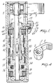
- Fig. 1 is a longitudinal cross section view of the operating device, according to the invention, with the selector positioned to operate the first pulley;
- Fig. 2 is a cross section view of the operating device, with the selector positioned to operate the second pulley;
- Fig. 3 is a cross section view of a detail of the device illustrating the selector in a neutral position disengaged from both pulleys;
- Fig. 4 is a schematic perspective view of the lever.
- With reference to the above described figures, the multiple-function operating device, particularly for ski boots, according to the invention, comprises a containment body, generally designated with the
reference numeral 1, which preferably, but not necessarily, has a substantially cylindrical elongated shape. - Said
containment body 1 is preferably, but not necessarily, supported on the rear portion of the rear quarter of a ski boot. - Proximate to its upper end, the containment body supports a lever, generally indicated by the
reference numeral 2, which has an arm 3 protruding from thecontainment body 1 through aslit 4. - The
lever 2 has acentral body 5, which is coupled, with the interposition of a ratchet-like assembly or ratchet pawl, generally indicated by the reference numeral 6 and of a per se known kind, with acentral axle 7, which is rotatably supported inside thecontainment body 1. - The ratchet-like assembly is intended to couple the
lever 2 rigidly in rotation when operated in one direction, allowing instead the uncoupling of the rotation in the return phase of the lever, which return can be provided, in a per se known manner, by elastic means. - A selector engages with the
central axle 7 slideably and rigidly in rotation, and is generally designated with thereference numeral 10, which has a bush-like body 11 accommodating in its interior theaxle 7, which, by means of akey 12, slideably engages with alongitudinal slit 13 provided on thecentral axle 7, so as to have theselector 10 rigidly coupled in rotation with respect to theaxle 7, but with the possibility of sliding in an axial direction. - The
selector 10 is upwardly provided with asliding ring 15, retained in position by means such as a Siegerring 17; thesliding ring 15 is provided with atab 18 which protrudes on the outside of thecontainment body 1 passing through alongitudinal opening 19 defined by thecontainment body 1. - A
selector button 20 is connected to thetab 18, which button is provided, on the side facing thecontainment body 1, with apositioning ball 22 pushed by aspring 23 which is accommodatable inpositioning recesses 24, defined on the outer surface of thecontainment body 1, so as to define preferential accommodation positions for thebutton 20 and consequently for the positioning of the selector inside saidcontainment body 1. - Proximate to its lower end, the
selector 10 is provided with acoupling gearwheel 30 which is selectively engageable with thegearwheel 31, correspondingly defined by afirst pulley 32, and with thegearwheel 33, correspondingly defined by asecond pulley 34. Thegearwheels coupling gearwheel 30, so as to create an intermediate neutral or free position, as will be better described hereinafter. - The
pulleys respective slots - Said pulleys are selectively engageable in rotation with the
axle 7 by means of the positioning of the selector, according to the coupling which is provided by thegearwheel 30 with thegearwheel - The
first pulley 32 is accommodated coaxially and externally to theselector 10 and is kept in position by means of anupper spacer 40, arranged inside thecontainment body 1 and anintermediate spacer 41 which axially separates thepulleys - On the
first pulley 32 act first removable means for blocking the rotation of the pulley in the direction of unwinding, which advantageously are composed of a first pin-spring 50 having an end fixed to the same pulley and the other end arranged on the internal surface of the containment body, so that a rotation of the pulley in the direction of unwinding is blocked by the radial expansion of the first pin-spring 50. A button is furthermore provided, which is accessible from the outside and is not illustrated in the drawings, which permits release of the pin-spring 50 allowing, when required, the rotation of the pulley in the direction of unwinding of the cable. - Similarly, on the
second pulley 34 second blocking means are provided, composed of a second pin-spring 51 having an end fixed to the same pulley and the other end acting on the internal surface of thecontainment body 1; also in this case, a button is provided, which is accessible from the outside and is not illustrated in the drawings, for releasing the blocking action exerted by the second pin-spring 51, if the unwinding of thesecond cable 36 is desired. - On the
first pulley 32 act furthermore first automatic cable rewinding means which are composed of a firstspiral spring 60 connected between thepulley 32 and the internal wall of thecontainment body 1, which in practice is elastically loaded by the unwinding of the cable and is therefore capable of automatically recovering the initial part of the cable, until the biasing action exerted by the cable itself balances the spring. The subsequent cable locking action is performed by acting on thelever 2. - Similarly, second automatic rewinding means for the second cable are provided, which are composed of a second
spiral spring 61 connected to thesecond pulley 34 and to the internal wall of thecontainment body 1, and acting similarly to what has been previously described. - The device is furthermore completed by anti-friction means which act on the pulleys and support the axle so as to reduce the forces.
- In practical operation, the above described operating device allows the centralization of all of the required actuations, since it is possible, by virtue of the
selector 10, to select the cable on which the traction is to be exerted. - As illustrated in Fig. 1, the selector, by means of the
selection button 20, is arranged in its lower position with thecoupling gearwheel 30 coupled with thegearwheel 31 of thefirst pulley 32, so that the rotation generated on theaxle 7 by means of thelever 2, causes the rotation in the direction of winding of thefirst pulley 32, with the consequent recovery of the cable orband 35, which is e.g. assigned to closing the quarters. - Once the required tightening action has been performed, it is sufficient to move the
selector 10, by means of theselection button 20, causing thecoupling gearwheel 30 to engage with thegearwheel 33 of thesecond pulley 34. - By repeating the alternate oscillation action of the
lever 2, in this case the second pulley is made to rotate, and consequently the second cable or band, which is, e.g., connected to the foot instep presser, is wound. - When the pulleys are not coupled with the gearwheel, the rotation in the direction of unwinding is prevented by the removable blocking means composed of the pin-
springs - To perform the releasing and therefore allow the rotation of the pulleys in the direction of unwinding of the cable, it is sufficient to position the selector in the free position with the
coupling gearwheel 30 not engaging any of the gearwheels of thepulleys springs - It should also be noted that during the rotation of the pulleys in the direction of unwinding of the cables the
spiral springs spiral springs - From what has been described, it can be seen that the invention achieves the proposed objects, and in particular the fact is stressed that a device is provided which allows centralization of all of the actuations in a point which is convenient for the user, allowing him the possibility, by simply acting on the
selection button 20, to perform each of the selected actuations, independently from one another when required. - Furthermore, another important feature of the invention is constituted by the fact that means for the elastic recovery of the initial portion of the length of the cable are provided, consequently expediting all the required actuations.
Claims (8)
- Multiple-function operating device particularly for ski boots, comprising a containment body (1), associable with a ski boot and supporting a lever (2), accessible from the outside and operatively connected, with the interposition of a ratchet assembly (6), to a central axle (7), rotatably supported by said containment body, characterized in that it comprises a selector (10), actuable from the outside of said containment body (1) and selectively couplable with a first (32) and at least a second (34) winding pulley, respectively of a first (35) and at least a second (36) cable and the like, there being furthermore provided means (50, 51) for removably locking the rotation of said pulleys (32, 34) in the direction of unwinding of the cables (35, 36).
- An operating device, according to the preceding claim, characterized in that said selector (10) has a bush-like body (11) arranged coaxially around said central axle (7), said bush-like body (11) being rigidly coupled in rotation with said central axle (7) and axially movable with respect to said central axle (7).
- An operating device, according to the preceding claims, characterized in that it comprises a sliding ring (15) rigidly associated with said selector (10) and having a tab (18) protruding from said containment body (1), to said tab (18) there being connected a selection button (20) for the motion in an axial direction of said selector (10).
- An operating device, according to one or more of the preceding claims, characterized in that said selection button (20) is provided with elastic positioning means composed of a ball (22) pushed by a spring (23) and engageable in positioning seats (24) provided on the outer surface of said containment body (1).
- An operating device, according to one or more of the preceding claims, characterized in that it comprises a coupling gearwheel (30) rigidly defined on said selector (10) and selectively associatable with a gearwheel (31), correspondingly defined by said first pulley (32), and with a gearwheel (33) matchingly defined by said at least one second pulley (34).
- An operating device, according to one or more of the preceding claims, characterized in that said gearwheels (31, 33) of said pulleys (32, 34) are separated from one another by a length which is substantially equal or greater than the axial length of the teeth of said gearwheel (30) to define a free position in which said selector (10) is uncoupled from said pulleys (32, 34).
- An operating device, according to one or more of the preceding claims, characterized in that said removable blocking means are composed of pin-springs (50, 51) having one end connected with the respective pulley (32 or 34) and the other end acting on the internal surface of said containment body (1), to prevent the rotation of the respective pulley in the direction of unwinding, buttons being provided which are accessible from the outside of said containment body (1) for disabling said pin-springs (50, 51).
- An operating device, according to one or more of the preceding claims, characterized in that it comprises automatic rewinding means for the initial portion of said cables (35, 36), composed of spiral springs (60, 61) having one end connected to the respective pulley (32, 34) and the other end connected to said containment body (1).
Priority Applications (1)
| Application Number | Priority Date | Filing Date | Title |
|---|---|---|---|
| AT87100150T ATE74257T1 (en) | 1986-01-13 | 1987-01-08 | DEVICE WITH MULTIPLE FUNCTIONS, ESPECIALLY FOR SKI BOOTS. |
Applications Claiming Priority (2)
| Application Number | Priority Date | Filing Date | Title |
|---|---|---|---|
| IT1906486 | 1986-01-13 | ||
| IT19064/86A IT1188254B (en) | 1986-01-13 | 1986-01-13 | MULTIPLE FUNCTION DRIVE DEVICE PARTICULARLY FOR SKI BOOTS |
Publications (3)
| Publication Number | Publication Date |
|---|---|
| EP0230879A2 EP0230879A2 (en) | 1987-08-05 |
| EP0230879A3 EP0230879A3 (en) | 1989-11-02 |
| EP0230879B1 true EP0230879B1 (en) | 1992-04-01 |
Family
ID=11154232
Family Applications (1)
| Application Number | Title | Priority Date | Filing Date |
|---|---|---|---|
| EP87100150A Expired - Lifetime EP0230879B1 (en) | 1986-01-13 | 1987-01-08 | Multiple-function operating device particularly for ski boots |
Country Status (6)
| Country | Link |
|---|---|
| US (1) | US4870723A (en) |
| EP (1) | EP0230879B1 (en) |
| JP (1) | JPS62170202A (en) |
| AT (1) | ATE74257T1 (en) |
| DE (1) | DE3777842D1 (en) |
| IT (1) | IT1188254B (en) |
Families Citing this family (58)
| Publication number | Priority date | Publication date | Assignee | Title |
|---|---|---|---|---|
| CH679265A5 (en) * | 1989-09-26 | 1992-01-31 | Raichle Sportschuh Ag | |
| EP0443363A1 (en) * | 1990-02-21 | 1991-08-28 | Raichle Sportschuh AG | Sports shoe, in particular a ski boot |
| US5341393A (en) * | 1990-05-10 | 1994-08-23 | Fuji Photo Film Co., Ltd. | Laser-diode-pumped solid-state laser |
| AT398688B (en) * | 1991-12-02 | 1995-01-25 | Dynafit Skischuh Gmbh | ADJUSTMENT SYSTEM FOR SKI SHOES |
| DE9200982U1 (en) * | 1992-01-28 | 1993-05-27 | Puma Ag Rudolf Dassler Sport, 8522 Herzogenaurach, De | |
| DE9209702U1 (en) * | 1992-07-22 | 1993-11-25 | Dassler Puma Sportschuh | Shoes, in particular sports, leisure or rehabilitation shoes |
| US20080060167A1 (en) | 1997-08-22 | 2008-03-13 | Hammerslag Gary R | Reel based closure system |
| US7591050B2 (en) * | 1997-08-22 | 2009-09-22 | Boa Technology, Inc. | Footwear lacing system |
| US20020095750A1 (en) * | 1997-08-22 | 2002-07-25 | Hammerslag Gary R. | Footwear lacing system |
| US20060156517A1 (en) | 1997-08-22 | 2006-07-20 | Hammerslag Gary R | Reel based closure system |
| US6416074B1 (en) | 1999-06-15 | 2002-07-09 | The Burton Corporation | Strap for a snowboard boot, binding or interface |
| US6267390B1 (en) | 1999-06-15 | 2001-07-31 | The Burton Corporation | Strap for a snowboard boot, binding or interface |
| US7076843B2 (en) * | 2003-10-21 | 2006-07-18 | Toshiki Sakabayashi | Shoestring tying apparatus |
| EP2789251A1 (en) * | 2004-10-29 | 2014-10-15 | Boa Technology, Inc. | Tightening mechanism for use with a footwear lacing system |
| WO2007081822A2 (en) * | 2006-01-06 | 2007-07-19 | Boa Technology, Inc. | Rough and fine adjustment closure system |
| KR101492477B1 (en) | 2006-09-12 | 2015-02-11 | 보아 테크놀러지, 인크. | Closure system for braces, protective wear and similar articles |
| KR20100129278A (en) | 2008-01-18 | 2010-12-08 | 보아 테크놀러지, 인크. | Closure system |
| EP2805639B2 (en) | 2008-11-21 | 2021-08-18 | Boa Technology, Inc. | Reel based lacing system |
| WO2011091325A1 (en) | 2010-01-21 | 2011-07-28 | Boa Technology, Inc. | Guides for lacing systems |
| US10070695B2 (en) | 2010-04-30 | 2018-09-11 | Boa Technology Inc. | Tightening mechanisms and applications including the same |
| US9375053B2 (en) | 2012-03-15 | 2016-06-28 | Boa Technology, Inc. | Tightening mechanisms and applications including the same |
| CN103153112B (en) | 2010-04-30 | 2015-06-17 | 博技术有限公司 | Reel based lacing system |
| US9149089B2 (en) | 2010-07-01 | 2015-10-06 | Boa Technology, Inc. | Lace guide |
| WO2012003396A2 (en) | 2010-07-01 | 2012-01-05 | Boa Technology, Inc. | Braces using lacing systems |
| US9101181B2 (en) | 2011-10-13 | 2015-08-11 | Boa Technology Inc. | Reel-based lacing system |
| US9179729B2 (en) | 2012-03-13 | 2015-11-10 | Boa Technology, Inc. | Tightening systems |
| EP3871548B1 (en) | 2012-08-31 | 2024-04-03 | NIKE Innovate C.V. | Motorized tensioning system |
| US9516923B2 (en) | 2012-11-02 | 2016-12-13 | Boa Technology Inc. | Coupling members for closure devices and systems |
| US9737115B2 (en) | 2012-11-06 | 2017-08-22 | Boa Technology Inc. | Devices and methods for adjusting the fit of footwear |
| EP3607845B1 (en) | 2013-01-28 | 2022-11-09 | Boa Technology Inc. | Lace fixation assembly and system |
| US10702409B2 (en) | 2013-02-05 | 2020-07-07 | Boa Technology Inc. | Closure devices for medical devices and methods |
| US9610185B2 (en) | 2013-03-05 | 2017-04-04 | Boa Technology Inc. | Systems, methods, and devices for automatic closure of medical devices |
| US10251451B2 (en) | 2013-03-05 | 2019-04-09 | Boa Technology Inc. | Closure devices including incremental release mechanisms and methods therefor |
| KR102426042B1 (en) | 2013-04-01 | 2022-07-28 | 보아 테크놀러지, 인크. | Methods and devices for retrofitting footwear to include a reel based closure system |
| KR20230057480A (en) | 2013-06-05 | 2023-04-28 | 보아 테크놀러지, 인크. | Integrated closure device components and methods |
| US10076160B2 (en) | 2013-06-05 | 2018-09-18 | Boa Technology Inc. | Integrated closure device components and methods |
| DE112014003135B4 (en) | 2013-07-02 | 2020-12-24 | Boa Technology Inc. | ROLL FOR USE WITH AN OBJECT TIGHTENING SYSTEM AND DEVICES THEREFORE AND METHOD OF ASSEMBLING AN OBJECTIVE TIGHTENING DEVICE |
| WO2015006616A1 (en) | 2013-07-10 | 2015-01-15 | Boa Technology Inc. | Closure devices including incremental release mechanisms and methods therefor |
| WO2015035257A2 (en) | 2013-09-05 | 2015-03-12 | Boa Technology Inc. | Alternative lacing guides for tightening mechanisms and methods therefor |
| KR102297325B1 (en) | 2013-09-13 | 2021-09-03 | 보아 테크놀러지, 인크. | Reel based closure device and method therefore |
| JP6526691B2 (en) | 2013-11-18 | 2019-06-05 | ボア テクノロジー,インコーポレイテッド | Method and apparatus for automatically closing a prosthetic device and a orthopedic support |
| USD835976S1 (en) | 2014-01-16 | 2018-12-18 | Boa Technology Inc. | Coupling member |
| USD751281S1 (en) | 2014-08-12 | 2016-03-15 | Boa Technology, Inc. | Footwear tightening reels |
| USD767269S1 (en) | 2014-08-26 | 2016-09-27 | Boa Technology Inc. | Footwear tightening reel |
| US20160058127A1 (en) | 2014-08-28 | 2016-03-03 | Boa Technology Inc. | Devices and methods for enhancing the fit of boots and other footwear |
| USD758061S1 (en) | 2014-09-08 | 2016-06-07 | Boa Technology, Inc. | Lace tightening device |
| WO2016054317A1 (en) | 2014-10-01 | 2016-04-07 | Ossur Hf | Support for articles and methods for using the same |
| WO2016057697A1 (en) | 2014-10-07 | 2016-04-14 | Boa Technology Inc. | A tension adjustment mechanism and a method for adjusting the fit of a shoe |
| USD835898S1 (en) | 2015-01-16 | 2018-12-18 | Boa Technology Inc. | Footwear lace tightening reel stabilizer |
| USD776421S1 (en) | 2015-01-16 | 2017-01-17 | Boa Technology, Inc. | In-footwear lace tightening reel |
| US10004297B2 (en) | 2015-10-15 | 2018-06-26 | Boa Technology Inc. | Lacing configurations for footwear |
| US11806264B2 (en) | 2016-05-03 | 2023-11-07 | Icarus Medical, LLC | Adjustable tensioning device |
| KR102391910B1 (en) | 2016-08-02 | 2022-04-28 | 보아 테크놀러지, 인크. | Tension member guides in shoelace tying systems |
| CN116831357A (en) | 2016-12-09 | 2023-10-03 | Boa科技股份有限公司 | Reel-based closure system |
| US10543630B2 (en) | 2017-02-27 | 2020-01-28 | Boa Technology Inc. | Reel based closure system employing a friction based tension mechanism |
| US11357279B2 (en) | 2017-05-09 | 2022-06-14 | Boa Technology Inc. | Closure components for a helmet layer and methods for installing same |
| US10772384B2 (en) | 2017-07-18 | 2020-09-15 | Boa Technology Inc. | System and methods for minimizing dynamic lace movement |
| EP3962316A4 (en) | 2019-05-01 | 2023-01-25 | Boa Technology Inc. | Reel based closure system |
Family Cites Families (11)
| Publication number | Priority date | Publication date | Assignee | Title |
|---|---|---|---|---|
| US371520A (en) * | 1887-10-11 | Means for operating ditching-machines | ||
| US522064A (en) * | 1894-06-26 | Tape-measure case | ||
| US695067A (en) * | 1901-07-15 | 1902-03-11 | Louise P Mallon | Hoisting or lowering apparatus for boats. |
| US941898A (en) * | 1908-08-04 | 1909-11-30 | George Talmadge Van Riper | Clothes-line hanger. |
| FR525207A (en) * | 1921-05-06 | 1921-09-17 | Cie D Entpr S Electro Mecaniqu | Twin-drum winches for plowing and other applications |
| US1543846A (en) * | 1924-04-03 | 1925-06-30 | Ingersoll Rand Co | Double-drum hoist |
| US3664599A (en) * | 1970-01-13 | 1972-05-23 | Robbins Seat Belt Co | Double locking retractable seat belt assembly |
| IT1135213B (en) * | 1981-01-28 | 1986-08-20 | Nordica Spa | HYDRAULIC DEVICE ESPECIALLY FOR CLOSING SS SKI BOOTS |
| IT1199519B (en) * | 1984-04-03 | 1988-12-30 | Kairos Di Bonetti M | LEG LOCKING DEVICE FOR REAR ENTRANCE SKI SHOES |
| IT1180988B (en) * | 1984-06-01 | 1987-09-23 | Caber Italia | CLAMPING AND ADJUSTMENT DEVICE PARTICULARLY FOR SKI BOOTS |
| FR2569087B1 (en) * | 1984-08-17 | 1987-01-09 | Salomon Sa | SKI BOOT |
-
1986
- 1986-01-13 IT IT19064/86A patent/IT1188254B/en active
-
1987
- 1987-01-08 EP EP87100150A patent/EP0230879B1/en not_active Expired - Lifetime
- 1987-01-08 DE DE8787100150T patent/DE3777842D1/en not_active Expired - Fee Related
- 1987-01-08 AT AT87100150T patent/ATE74257T1/en not_active IP Right Cessation
- 1987-01-13 JP JP62004199A patent/JPS62170202A/en active Pending
-
1988
- 1988-11-14 US US07/274,692 patent/US4870723A/en not_active Expired - Fee Related
Also Published As
| Publication number | Publication date |
|---|---|
| DE3777842D1 (en) | 1992-05-07 |
| US4870723A (en) | 1989-10-03 |
| EP0230879A3 (en) | 1989-11-02 |
| IT8619064A0 (en) | 1986-01-13 |
| IT1188254B (en) | 1988-01-07 |
| ATE74257T1 (en) | 1992-04-15 |
| EP0230879A2 (en) | 1987-08-05 |
| JPS62170202A (en) | 1987-07-27 |
Similar Documents
| Publication | Publication Date | Title |
|---|---|---|
| EP0230879B1 (en) | Multiple-function operating device particularly for ski boots | |
| EP0398119B1 (en) | Fastening and adjusting device, particularly for ski boots | |
| EP0201051B1 (en) | Ski boot | |
| EP0166961B1 (en) | Tightening and adjusting device particularly for ski boots | |
| US5001817A (en) | Securing and adjustment device particularly for ski boots | |
| EP0290847B1 (en) | Locking and adjustment device particularly for ski boots | |
| US4841649A (en) | Locking and adjustment device particularly for ski boots | |
| US4787124A (en) | Multiple-function actuation device particularly usable in ski boots | |
| US4719710A (en) | Operating device for foot locking elements, particularly for ski boots | |
| EP0263440B1 (en) | Closure and securing device, particularly for ski boots | |
| EP0809950B1 (en) | A device for adjusting and clamping the toothed strap of a fastening for sports footwear | |
| EP0232801B1 (en) | Device for closing quarters, particularly for ski boots | |
| EP0824942A1 (en) | Binding for a snowboard | |
| JPS62112503A (en) | Ski boots with closing device and foot fixing device | |
| EP0361066B1 (en) | Ski boot | |
| JPH08503147A (en) | Shoes with a tightening system with tensile force memory function | |
| JPS6040010A (en) | Actuator for foot upper press element | |
| US5012598A (en) | Foot securing device with automatic release, particularly for rear-entry ski boots | |
| EP0351653B1 (en) | Securing and adjuster device, particularly for ski boots | |
| US5341584A (en) | Ski boot having a closure device | |
| US5107609A (en) | Ski boot with improved fit | |
| EP0234317A2 (en) | Locking device particularly for ski boots | |
| US5351420A (en) | Ski boot with a lever having independent adjustment devices | |
| JPH0667715B2 (en) | Seat belt retractor | |
| EP1023847B1 (en) | Adjuster device for sports shoes |
Legal Events
| Date | Code | Title | Description |
|---|---|---|---|
| PUAI | Public reference made under article 153(3) epc to a published international application that has entered the european phase |
Free format text: ORIGINAL CODE: 0009012 |
|
| AK | Designated contracting states |
Kind code of ref document: A2 Designated state(s): AT CH DE FR LI |
|
| PUAL | Search report despatched |
Free format text: ORIGINAL CODE: 0009013 |
|
| AK | Designated contracting states |
Kind code of ref document: A3 Designated state(s): AT CH DE FR LI |
|
| 17P | Request for examination filed |
Effective date: 19891116 |
|
| RAP1 | Party data changed (applicant data changed or rights of an application transferred) |
Owner name: NORDICA S.P.A. |
|
| 17Q | First examination report despatched |
Effective date: 19910514 |
|
| GRAA | (expected) grant |
Free format text: ORIGINAL CODE: 0009210 |
|
| AK | Designated contracting states |
Kind code of ref document: B1 Designated state(s): AT CH DE FR LI |
|
| REF | Corresponds to: |
Ref document number: 74257 Country of ref document: AT Date of ref document: 19920415 Kind code of ref document: T |
|
| REF | Corresponds to: |
Ref document number: 3777842 Country of ref document: DE Date of ref document: 19920507 |
|
| ET | Fr: translation filed | ||
| PG25 | Lapsed in a contracting state [announced via postgrant information from national office to epo] |
Ref country code: AT Effective date: 19930108 |
|
| PG25 | Lapsed in a contracting state [announced via postgrant information from national office to epo] |
Ref country code: LI Effective date: 19930131 Ref country code: CH Effective date: 19930131 |
|
| PLBE | No opposition filed within time limit |
Free format text: ORIGINAL CODE: 0009261 |
|
| STAA | Information on the status of an ep patent application or granted ep patent |
Free format text: STATUS: NO OPPOSITION FILED WITHIN TIME LIMIT |
|
| 26N | No opposition filed | ||
| PG25 | Lapsed in a contracting state [announced via postgrant information from national office to epo] |
Ref country code: FR Effective date: 19930930 |
|
| REG | Reference to a national code |
Ref country code: CH Ref legal event code: PL |
|
| PG25 | Lapsed in a contracting state [announced via postgrant information from national office to epo] |
Ref country code: DE Effective date: 19931001 |
|
| REG | Reference to a national code |
Ref country code: FR Ref legal event code: ST |