EP0230591A2 - Girder - Google Patents
Girder Download PDFInfo
- Publication number
- EP0230591A2 EP0230591A2 EP86117285A EP86117285A EP0230591A2 EP 0230591 A2 EP0230591 A2 EP 0230591A2 EP 86117285 A EP86117285 A EP 86117285A EP 86117285 A EP86117285 A EP 86117285A EP 0230591 A2 EP0230591 A2 EP 0230591A2
- Authority
- EP
- European Patent Office
- Prior art keywords
- longitudinal
- webs
- profile bar
- carrier
- approximately
- Prior art date
- Legal status (The legal status is an assumption and is not a legal conclusion. Google has not performed a legal analysis and makes no representation as to the accuracy of the status listed.)
- Granted
Links
- 230000007704 transition Effects 0.000 claims abstract description 5
- 239000006260 foam Substances 0.000 claims description 3
- 239000011324 bead Substances 0.000 claims description 2
- 239000000969 carrier Substances 0.000 description 5
- 238000005452 bending Methods 0.000 description 3
- 238000010276 construction Methods 0.000 description 3
- 230000001133 acceleration Effects 0.000 description 2
- 101100390736 Danio rerio fign gene Proteins 0.000 description 1
- 101100390738 Mus musculus Fign gene Proteins 0.000 description 1
- 230000001154 acute effect Effects 0.000 description 1
- 230000005540 biological transmission Effects 0.000 description 1
- 238000004519 manufacturing process Methods 0.000 description 1
Images
Classifications
-
- E—FIXED CONSTRUCTIONS
- E04—BUILDING
- E04C—STRUCTURAL ELEMENTS; BUILDING MATERIALS
- E04C3/00—Structural elongated elements designed for load-supporting
- E04C3/02—Joists; Girders, trusses, or trusslike structures, e.g. prefabricated; Lintels; Transoms; Braces
- E04C3/04—Joists; Girders, trusses, or trusslike structures, e.g. prefabricated; Lintels; Transoms; Braces of metal
- E04C3/08—Joists; Girders, trusses, or trusslike structures, e.g. prefabricated; Lintels; Transoms; Braces of metal with apertured web, e.g. with a web consisting of bar-like components; Honeycomb girders
-
- B—PERFORMING OPERATIONS; TRANSPORTING
- B25—HAND TOOLS; PORTABLE POWER-DRIVEN TOOLS; MANIPULATORS
- B25J—MANIPULATORS; CHAMBERS PROVIDED WITH MANIPULATION DEVICES
- B25J18/00—Arms
- B25J18/02—Arms extensible
- B25J18/025—Arms extensible telescopic
-
- E—FIXED CONSTRUCTIONS
- E04—BUILDING
- E04C—STRUCTURAL ELEMENTS; BUILDING MATERIALS
- E04C3/00—Structural elongated elements designed for load-supporting
- E04C3/02—Joists; Girders, trusses, or trusslike structures, e.g. prefabricated; Lintels; Transoms; Braces
- E04C3/04—Joists; Girders, trusses, or trusslike structures, e.g. prefabricated; Lintels; Transoms; Braces of metal
- E04C2003/0486—Truss like structures composed of separate truss elements
- E04C2003/0495—Truss like structures composed of separate truss elements the truss elements being located in several non-parallel surfaces
Definitions
- the invention relates to a carrier having at least one profile bar and at least one supporting wall or a supporting body.
- Carriers are required in a wide variety of designs, for example in crane construction or the devices.
- a special area of application for such carriers of the devices is, for example, handling devices such as those used more recently in modern manufacturing processes.
- handling devices with straight basic axes, carriers have to be mounted in a longitudinally displaceable manner on other carriers, which in turn are also moved.
- the slidable storage takes place via rollers, wheels of the like elements. Because the movements are very fast, high axis accelerations occur, which put a heavy load on the beams. As a result, they must be particularly stable. The requirement for high stability is opposed to that for light weight and small acceleration forces.
- the object of the invention is therefore to develop a carrier having at least one profile bar, which enables a lightweight construction due to special profile bar design without impairing rigidity and stability.
- the carrier is designed according to the preamble of claim 1 in accordance with the characterizing part of this claim.
- An essential feature of this carrier is therefore the special design of the profile bar, on the running surface of which the wheel or wheels or the like.
- Another carrier or a carriage or the like are moved along. A force is introduced into the profile bar via the impeller or wheels, which force is derived via the two webs onto the supporting wall or a supporting body.
- the part slidably mounted thereon is only slidably supported on this carrier.
- the total required treads are on at least one profile bar of each carrier.
- the treads are located on two profile bars.
- the carrier can be used particularly universally and one is not subjected to excessive restrictions in this way with regard to the carriages or the like. It is easily possible to provide five or six treads on a single profile bar, which may also be used in pairs or in pairs. In addition, the treads do not have to be particularly pronounced surfaces, but can also be act a flank of a prismatic body or a portion of a wall that does not necessarily have to be flat. In other words, you can move the impeller (s) along an outer surface of the profile bar at the desired location.
- the only decisive factor is that the normal to the touch ellipse runs through the common profile axis, which is defined by the intersection of the center planes through the two webs. It also follows from this that the wheels are, in particular, spherical or spherical wheels. It also follows from this that the "treads" can be relatively narrow if there are any pronounced treads on the outer surface of the profile bar.
- the or each profile bar is thus a load introduction element, via which wheel forces are introduced into the carrier, the latter being a support element or a support body.
- the carrier or the supporting element in turn forwards the forces applied to any supports or a further supporting element.
- a particularly preferred embodiment of the invention is characterized in that the cross section of each profiled bar is symmetrical to an imaginary longitudinal plane through the bisector of the angle enclosed by the two longitudinal webs, the longitudinal webs preferably having a rectangular cross section.
- every profile bar exists from a basic body with one or more treads and two longitudinal bars. The latter are preferably made in one piece with the base body.
- the cross section of the profile bar without longitudinal webs is circular in a further embodiment of the invention.
- an elliptical or possibly also oval cross section can also be expedient.
- the running surfaces do not necessarily have to be present in raised or recessed form, rather they can be formed by partial surfaces of the cylinder jacket. They do not necessarily have to stand out physically, but they may be recognizable by a better surface structure.
- the two webs preferably enclose an angle of approximately 30 ° to 90 °, but in particular of approximately 60 °.
- a further embodiment of the invention is characterized in that the cross section of the profile bar without webs is approximately trapezoidal, the webs being assigned to the short baseline.
- Trapezoid here is not understood to mean the general trapezoidal shape, but the symmetrical trapezoid with inclined surfaces of equal strength, but inclined in opposite directions.
- a further development of the invention is characterized in that the cross-section of the profile bar has approximately the shape of two hexagon faces of different sizes, with their dividing surfaces centered on one another, separated by a corner, a longitudinal web being attached to the two corners of the larger hexagon half and the two longitudinal webs one Include angles of preferably about 60 °.
- This cross-sectional shape is optimal in that it offers the possibility of providing a whole series of running surfaces.
- the overall cross-section is relatively small, which benefits the desired lightweight construction.
- the central hexagonal area of the larger hexagonal half can be slightly grooved according to the drawing of the exemplary embodiment. For the same reason, the removal of the two free corners of the larger hexagon half by the amount also apparent from FIG. 4 is possible and advantageous.
- each outer surface of the smaller half hexagonal prism carries, forms or has one of three running surfaces and one of the two outer surfaces of the larger hexagonal prism each has one of two running surfaces.
- the corner dimensions of the large and the small hexagon preferably behave approximately as 2: 1.
- this cross-sectional shape is not the only possible use of this cross-sectional shape, but only a preferred one.
- each support wall consists of two thin plate-like elements with a honeycomb or rigid foam core connecting them. These connecting walls are characterized on the one hand by their low weight and on the other hand by their good stability and dimensional stability. They are comparable to a sandwich plate.
- the plate-like elements of the supporting wall protrude particularly seen advantageously the core in the transverse direction of the profile bar and the projecting ends are each firmly connected to the two outer surfaces of the associated longitudinal web.
- the plate-like elements are expediently glued, riveted or screwed onto the longitudinal webs. Between the projecting ends of the two free supporting walls, a somewhat more stable end bar is advantageously used, which runs in particular parallel to the respective longitudinal web.
- the carrier 1 shown in Fig. 1 consists of two profile bars 2 of the same cross-sectional shape, which are connected to each other via a support wall 3 and each of which is connected to a further support wall 4 or 5. In this way, a carrier is created sen shape is comparable to that of a triangular tube. For the sake of clarity, the cross sections of the profile bars are exaggerated.
- the profile bars shown in FIG. 1 correspond to the embodiment according to FIG. 4.
- the profile bar shown in Fig. 3 has a base body 6, which can be described as trapezoidal or approximately triangular. With this base body two longitudinal webs 7 and 8 are connected at an angle to each other, in particular manufactured in one piece. They enclose an acute angle 21 of, for example, approximately 60 °.
- tread 12, 13, 14 on at least one, but preferably all three triangular flanks of the triangular base 6.
- These treads are shown as raised treads both in this figure and in FIGS. 2 and 4 for the sake of clarity. However, this is by no means necessary, rather the running surfaces can be partial surfaces of the triangular flanks 9, 10, 11. It is also possible that the treads are formed by groove-like depressions in the triangular flanks. It is only important that the normals to the treads or imaginary perpendicular planes 15, 16, 17, which are perpendicular to the triangular flanks and in particular pass through the center of the tread, intersect in a common longitudinal axis 18 of the profile.
- the base body 22 has a circular cross section, i.e. the basic body has the shape of a circular cylinder.
- the two longitudinal webs 23 and 24 form a right or smaller angle in the exemplary embodiment. Only three treads 25, 26, 27 are shown, for example.
- FIG. 2 The three supporting walls 3, 4, 5, which are only shown schematically in FIG. 1, are drawn in more detail in FIG. 2.
- Each consists of two parallel thin plate-like elements 28 and 29 and a honeycomb or rigid foam core 30 connecting them.
- the plate-like elements preferably protrude beyond the core 30 in the transverse direction of the profile bar 2. This allows them with their projecting edges on the two parallel outer surfaces of the in the Gap between the elements 28 and 29 engaging longitudinal web 23 and 24 are attached. 2 is designated as a whole by 31.
- FIG. 4 shows a third, preferred exemplary embodiment of a profiled rod, which is designated by 2. It has a cross-sectional shape, which can be essentially as follows can write. It consists of two hexagon halves 33 and 34 of different sizes with their separating surfaces placed in the middle, the hexagons being severed at a corner.
- the base body 43 accordingly consists of a larger and a smaller hexagonal prism half.
- the corner dimensions or circumferential diameter of the hexagons of the larger and smaller hexagon behave approximately like 2: 1.
- the central hexagonal surface of the larger hexagonal half according to FIG. 4 can be provided with a groove 35 or the like.
- the two free corners 38, 39 of the larger hexagon half can also be removed somewhat.
- the parts that have been taken away in terms of ideas are drawn partly by dash-dotted lines and partly by the actual contour lines in FIG. 4.
- This profile bar can have, for example and preferably five treads 44 to 48.
- the treads 44 and 47 on the one hand and 45 and 46 on the other hand each form a pair of treads for a corresponding pair of wheels or pairs of wheels.
- two profiled bars of this type on a carrier not all but normally only a part of the treads or pairs of treads are used, in particular the treads 44, 45, 48 on one and 44, 47 or 45, 46 on the other tread bar.
- each web 23, 24 and the adjoining plane support wall 3, 4 lie in a common plane. If the supporting walls are not flat, but are, for example, arched, angular or of a completely different shape, it is in any case true that a common plane must be present in the transition area from the longitudinal web to the subsequent longitudinal supporting wall area. In other words, for example in the case of a flat longitudinal web and a flat supporting wall, the longitudinal center planes of these two elements should not enclose an angle.
- the carrier according to the invention can also consist of only a single profile bar and a single supporting wall, the profile bar also having two longitudinal webs in this case, it is easy to see that each of these two longitudinal webs is or can be assigned a longitudinal edge of the supporting wall.
- the cross-sectional shape of the supporting wall could be approximately C-shaped, for example.
- the supporting wall primarily determines the shear stiffness of the girder, while the profile bars used for load control determine the bending stiffness of the girder.
- the load-bearing capacity of the entire beam is only achieved by combining the two elements.
- the thickness of the thin-walled plate is in particular less than the thickness of the longitudinal webs 7 and 8. It is preferably about 0.3 to 5 mm. At the transition to the associated longitudinal web 7, 8, it may be necessary to adjust the thickness.
- each support wall consists of two thin-walled plates which are connected to one another by webs, the webs in particular running parallel to the longitudinal direction of the carrier.
- the thickness of each of these two plates is preferably on the order of 0.3 to 1.5 mm. This then results in a total thickness of up to approx. 6 or 8 mm.
- This supporting wall can, for example, be connected to the associated longitudinal web in the manner shown in FIG. 2. In the aforementioned case, too, an encirclement of the longitudinal web can be provided, in which case the end region of the thin-walled plate must then be correspondingly adapted in shape.
Landscapes
- Engineering & Computer Science (AREA)
- Architecture (AREA)
- Civil Engineering (AREA)
- Structural Engineering (AREA)
- Robotics (AREA)
- Mechanical Engineering (AREA)
- Rod-Shaped Construction Members (AREA)
- Bridges Or Land Bridges (AREA)
- Pallets (AREA)
- Handcart (AREA)
- Paper (AREA)
- Glass Compositions (AREA)
- Surgical Instruments (AREA)
Abstract
Der Träger (1) besteht aus wenigstens einem Profilstab (2) und mindestens einer Tragwand (3, 4, 5). Vorzugsweise ist der Träger (1) aus zwei Profilstäben (2) aufgebaut, die zwei Ecken eines, insbesondere im Bereich der dritten Ecke, längs geschlitzten Dreikantrohres markieren und welche bei diesem Beispiel mit drei Tragwänden (3, 4, 5) verbunden sind. Jeder Profilstab (2) besitzt zwei Längsstege (z.B. 7, 8), an denen je ein Ende der bzw. einer Tragwand (3, 4, 5) befestigt ist, wobei der Übergangsbereich zwischen beiden eben verläuft. An jedem Profilstab (2) ist mindestens eine Lauffläche (z.B. 12, 13, 14), wobei es sich durchaus um eine nicht körperlich abgetrennte Teilfläche des Profilstabmantels handeln kann. Gedachte Längsmittelebenen (19, 20) der Längsstege (z.B. 7, 8) schneiden sich in einer gemeinsamen Profillängsachse (18). Durch diese verlaufen auch sich senkrecht zu jeder Lauffläche erstrekkende gedachte Längsebenen (15, 16, 17). Dadurch entsteht ein verbeulsicherer und verformungsfester hohler Träger (1).The carrier (1) consists of at least one profile bar (2) and at least one supporting wall (3, 4, 5). The carrier (1) is preferably constructed from two profiled bars (2) which mark two corners of a triangular tube which is longitudinally slotted, in particular in the region of the third corner, and which in this example are connected to three supporting walls (3, 4, 5). Each profile bar (2) has two longitudinal webs (e.g. 7, 8), to each of which one end of the or one supporting wall (3, 4, 5) is attached, with the transition area between the two running flat. There is at least one tread (e.g. 12, 13, 14) on each profile bar (2), which may well be a part of the profile bar jacket that is not physically separated. Imagined longitudinal center planes (19, 20) of the longitudinal webs (e.g. 7, 8) intersect in a common longitudinal axis (18). These also run imaginary longitudinal planes (15, 16, 17) extending perpendicular to each tread. This creates a dent-proof and deformation-resistant hollow support (1).
Description
Die Erfindung bezieht sich auf einen wenigstens einen Profilstab und mindestens eine Tragwand oder einen Tragkörper aufweisenden Träger. Träger werden in den verschiedensten Ausführungen, beispielsweise im Kranbau oder der Vorrichtungen, benötigt. Ein spezielles Anwendungsgebiet solcher Träger der Vorrichtungen sind beispielsweise Handhabungsgeräte, wie man sie in neuerer Zeit bei modernen Fertigungsverfahren einsetzt. Bei Handhabungsgeräten mit geradlinigen Grundachsen müssen Träger längsverschieblich auf anderen Trägern gelagert werden, die ihrerseits ebenfalls bewegt werden. Die verschiebbare Lagerung erfolgt über Rollen, Räder der od. dgl. Elemente. Weil die Bewegungen sehr schnell ablaufen, treten hohe Achsbeschleunigungen auf, welche die Träger stark belasten. Sie müssen infolgedessen besonders stabil sein. Das Erfordernis nach hoher Stabilität steht aber demjenigen nach geringem Gewicht und kleinen Beschleunigungskräften entgegen.The invention relates to a carrier having at least one profile bar and at least one supporting wall or a supporting body. Carriers are required in a wide variety of designs, for example in crane construction or the devices. A special area of application for such carriers of the devices is, for example, handling devices such as those used more recently in modern manufacturing processes. In the case of handling devices with straight basic axes, carriers have to be mounted in a longitudinally displaceable manner on other carriers, which in turn are also moved. The slidable storage takes place via rollers, wheels of the like elements. Because the movements are very fast, high axis accelerations occur, which put a heavy load on the beams. As a result, they must be particularly stable. The requirement for high stability is opposed to that for light weight and small acceleration forces.
Die Aufgabe der Erfindung besteht infolgedessen darin, einen wenigstens einen Profilstab aufweisenden Träger zu entwickeln, der aufgrund spezieller Profilstabausbildung ohne Beeinträchtigung von Steifigkeit und Stabilität eine Leichtbauweise ermöglicht.The object of the invention is therefore to develop a carrier having at least one profile bar, which enables a lightweight construction due to special profile bar design without impairing rigidity and stability.
Zur Lösung dieser Aufgabe wird erfindungsgemäß vorgeschlagen, daß der Träger gemäß dem Oberbegriff des Anspruchs 1 entsprechend dem kennzeichnenden Teil dieses Anspruchs ausgebildet ist. Ein wesentliches Merkmal dieses Trägers ist also die spezielle Ausbildung des Profilstabs, an dessen Lauffläche das oder die Laufräder od. dgl. eines anderen Trägers oder eines Laufwagens od. dgl. entlangbewegt werden. Über das oder die Laufräder wird eine Kraft in den Profilstab eingeleitet, die über die beiden Stege auf die Tragwand oder einen Tragkörper abgeleitet wird. Aufgrund der speziellen Zuordnung der Lauffläche oder Laufflächen zu den beiden Stegen einerseits und dieses Stegs zu seiner anschließenden Tragwand andererseits erreicht man eine optimale Weiterleitung der über die Räder auf den bzw. ihren Profilstab eingeleiteten Kräfte an die anschließende Tragwand oder einen Tragkörper, wobei in den Stegen und Tragwänden lediglich Scheibennormalspannungen und Scheibenschubspannungen auftreten. Weil die an den Steg anschließende Tragwand, zumindest im Übergangsbereich, mit dem Steg eine gemeinsame Ebene bildet, können dort nur Scheibenspannungen aber keine Biegespannungen und Biegeverformungen auftreten.To achieve this object, it is proposed according to the invention that the carrier is designed according to the preamble of
Bei der Ein-Träger-Lösung wird das daran verschiebbar gelagerte Teil lediglich an diesem Träger verschiebbar gelagert. Andererseits ist es aber auch möglich, zwei derartige Träger in paralleler Anordnung zu verwenden und an beiden gemeinsam einen weiteren Träger od. dgl. verschiebbar zu lagern. Im letzteren Falle befinden sich die insgesamt benötigten Laufflächen an zumindest je einem Profilstab jedes Trägers. Bei der Ein-Träger-Lösung befinden sich die Laufflächen an zwei Profilstäben. Im übrigen ist es durchaus möglich, bei einem Träger mit mehr als einem Profilstab an allen Profilstäben mehrere, an deren umfang versetzt angeordnete Laufflächen vorzusehen, von denen in einem speziellen Anwendungsfall aber möglicherweise nur eine bzw. ein Teil benutzt wird. Dadurch ist der Träger besonders universell einsetzbar und man ist auf diese Weise hinsichtlich der Laufwagen od. dgl. keinen zu großen Einschränkungen unterworfen. Es ist ohne weiteres möglich, an einem einzigen Profilstab fünf oder sechs Laufflächen vorzusehen, die man gegebenenfalls auch paarweise oder zu mehreren verwendet. Im übrigen müssen die Laufflächen nicht besonders ausgeprägte Flächen sein, vielmehr kann es sich dabei auch um eine Flanke eines prismatischen Körpers oder einen Teilbereich einer Wandung handeln, die nicht notwendigerweise eben sein muß. Anders ausgedrückt kann man entlang einer Mantelfläche des Profilstabs an der gewünschten Stelle das oder die Laufräder entlangbewegen. Maßgeblich ist lediglich, daß die Normale auf die Berührellipse durch die gemeinsame Profilachse verläuft, welche durch die Schnittlinie der Mittelebenen durch die beiden Stege definiert ist. Hieraus folgt auch, daß es sich bei den Laufrädern, insbesondere um kugelige oder ballige Räder handelt. Hieraus ergibt sich des weiteren, daß die "Laufflächen" verhältnismäßig schmal sein können, sofern überhaupt ausgeprägte Laufflächen auf der Mantelfläche des Profilstabs vorhanden sind.In the single-carrier solution, the part slidably mounted thereon is only slidably supported on this carrier. On the other hand, it is also possible to use two such carriers in a parallel arrangement and to jointly mount a further carrier or the like on both of them. In the latter case, the total required treads are on at least one profile bar of each carrier. In the single-beam solution, the treads are located on two profile bars. Moreover, it is entirely possible to provide several, on their circumferentially offset treads on a beam with more than one profile bar on all profile bars, of which, however, possibly only one or a part is used in a special application. As a result, the carrier can be used particularly universally and one is not subjected to excessive restrictions in this way with regard to the carriages or the like. It is easily possible to provide five or six treads on a single profile bar, which may also be used in pairs or in pairs. In addition, the treads do not have to be particularly pronounced surfaces, but can also be act a flank of a prismatic body or a portion of a wall that does not necessarily have to be flat. In other words, you can move the impeller (s) along an outer surface of the profile bar at the desired location. The only decisive factor is that the normal to the touch ellipse runs through the common profile axis, which is defined by the intersection of the center planes through the two webs. It also follows from this that the wheels are, in particular, spherical or spherical wheels. It also follows from this that the "treads" can be relatively narrow if there are any pronounced treads on the outer surface of the profile bar.
Der bzw. jeder Profilstab ist somit ein Lasteinleitungselement, über welches Radkräfte in den Träger eingeleitet werden, wobei letzterer ein Tragelement bzw. ein Tragkörper ist. Der Träger bzw. das Tragelement leitet seinerseits die aufgegebenen Kräfte an irgendwelche Stützen oder ein weiteres stützendes Element weiter.The or each profile bar is thus a load introduction element, via which wheel forces are introduced into the carrier, the latter being a support element or a support body. The carrier or the supporting element in turn forwards the forces applied to any supports or a further supporting element.
Eine besonders bevorzugte Ausführungsform der Erfindung kennzeichnet sich dadurch, daß der Querschnitt jedes Profilstabs zu einer gedachten Längsebene durch die Winkelhalbierende des von den beiden Längsstegen eingeschlossenen Winkels symmetrisch ausgebildet ist, wobei die Längsstege vorzugsweise einen rechteckigen Querschnitt aufweisen. Jeder Profilstab besteht gewissermaßen aus einem Grundkörper mit der oder den Laufflächen und zwei Längsstegen. Letztere sind vorzugsweise einstückig mit dem Grundkörper hergestellt.A particularly preferred embodiment of the invention is characterized in that the cross section of each profiled bar is symmetrical to an imaginary longitudinal plane through the bisector of the angle enclosed by the two longitudinal webs, the longitudinal webs preferably having a rectangular cross section. In a sense, every profile bar exists from a basic body with one or more treads and two longitudinal bars. The latter are preferably made in one piece with the base body.
Der Querschnitt des Profilstabs ohne Längsstege ist in weiterer Ausgestaltung der Erfindung kreisförmig. Unter Bezugnahme auf das Vorstehende bedeutet dies, daß der Querschnitt des Grundkörpers eine Kreisform besitzt und daran bei dieser, wie auch bei allen anderen Ausführungsformen, zwei Stege angesetzt sind. Anstelle eines kreisförmigen Querschnitts kann auch ein elliptischer oder eventuell auch ovaler Querschnitt zweckmäßig sein.The cross section of the profile bar without longitudinal webs is circular in a further embodiment of the invention. With reference to the foregoing, this means that the cross section of the base body has a circular shape and two webs are attached to it, as in all other embodiments. Instead of a circular cross section, an elliptical or possibly also oval cross section can also be expedient.
Die Laufflächen müssen nicht notwendigerweise in erhabener oder vertiefter Form vorhanden sein, vielmehr können sie durch Teilflächen des Zylindermantels gebildet sein. Sie brauchen körperlich nicht unbedingt hervorzutreten, können aber gegebenenfalls durch eine bessere Oberflächenstruktur erkennbar sein. Die beiden Stege schließen in bevorzugter Weise einen Winkel von etwa 30° bis 90°, insbesondere aber von etwa 60° ein.The running surfaces do not necessarily have to be present in raised or recessed form, rather they can be formed by partial surfaces of the cylinder jacket. They do not necessarily have to stand out physically, but they may be recognizable by a better surface structure. The two webs preferably enclose an angle of approximately 30 ° to 90 °, but in particular of approximately 60 °.
Eine weitere Ausgestaltung der Erfindung kennzeichnet sich dadurch, daß der Querschnitt des Profilstabs ohne Stege etwa trapezförmig ist, wobei die Stege der kurzen Grundlinie zugeordnet sind. Unter Trapez wird hier nicht die allgemeine Trapezform, sondern das symmetrische Trapez mit gleichstark, aber gegenläufig geneigten Schrägflächen verstanden.A further embodiment of the invention is characterized in that the cross section of the profile bar without webs is approximately trapezoidal, the webs being assigned to the short baseline. Trapezoid here is not understood to mean the general trapezoidal shape, but the symmetrical trapezoid with inclined surfaces of equal strength, but inclined in opposite directions.
Eine Weiterbildung der Erfindung kennzeichnet sich dadurch, daß der Querschnitt des Profilstabs etwa die Gestalt zweier mit ihren Trennflächen mittig aneinandergesetzter, unterschiedlich großer, über Eck durchtrennter Sechseckflächen aufweist, wobei an die beiden Ecken der größeren Sechseckhälfte je ein Längssteg angesetzt ist und die beiden Längsstege einen Winkel von vorzugsweise etwa 60° einschließen. Diese Querschnittsform ist insofern optimal als sie die Möglichkeit bietet, eine ganze Reihe von Laufflächen vorzusehen. Andererseits ist der Querschnitt insgesamt verhältnismäßig klein, was der angestrebten Leichtbauweise zugute kommt. Zur weiteren Gewichtsreduzierung kann man die mittlere Sechseckfläche der größeren Sechseckhälfte gemäß der zeichnerischen Darstellung des Ausführungsbeispiels noch etwas auskehlen. Aus demselben Grunde ist das Abnehmen der beiden freien Ecken der größeren Sechseckhälfte um den ebenfalls aus Fig. 4 ersichtlichen Betrag möglich und vorteilhaft.A further development of the invention is characterized in that the cross-section of the profile bar has approximately the shape of two hexagon faces of different sizes, with their dividing surfaces centered on one another, separated by a corner, a longitudinal web being attached to the two corners of the larger hexagon half and the two longitudinal webs one Include angles of preferably about 60 °. This cross-sectional shape is optimal in that it offers the possibility of providing a whole series of running surfaces. On the other hand, the overall cross-section is relatively small, which benefits the desired lightweight construction. To further reduce the weight, the central hexagonal area of the larger hexagonal half can be slightly grooved according to the drawing of the exemplary embodiment. For the same reason, the removal of the two free corners of the larger hexagon half by the amount also apparent from FIG. 4 is possible and advantageous.
Eine besonders bevorzugte Ausführungsform ist dadurch gekennzeichnet, daß jede Außenfläche des kleineren halben Sechskantprismas je eine von drei Laufflächen und je eine der beiden Außenflächen des größeren Sechskantprismas je eine von zwei Laufflächen tragen, bilden oder aufweisen. In bevorzugter Weise verhalten sich die Eckmaße des großen und des kleinen Sechsecks etwa wie 2:1.A particularly preferred embodiment is characterized in that each outer surface of the smaller half hexagonal prism carries, forms or has one of three running surfaces and one of the two outer surfaces of the larger hexagonal prism each has one of two running surfaces. The corner dimensions of the large and the small hexagon preferably behave approximately as 2: 1.
Es ist insbesondere daran gedacht, daß man bei einem zwei derartige Profilstäbe aufweisenden Träger das daran verschiebbare Ele ment am einen Profilstab an der mittleren Lauffläche des kleineren halben Sechskantprismas sowie den beiden außenliegenden Laufflächen des größeren halben Sechskantprismas und am anderen Profilstab an einem Laufflächenpaar lagert, welches durch je eine Lauffläche des größeren halben Sechskantprismas und eine gegenüberliegende Lauffläche des kleineren halben Sechskantprismas gebildet ist. Dies stellt allerdings nicht die einzige mögliche Ausnutzung dieser Querschnittsform dar, sonderen lediglich eine bevorzugte.It is particularly contemplated that in a carrier having two such profile bars, the displaceable Ele on one profile bar on the middle tread of the smaller half-hexagon prism and the two outer treads of the larger half-hexagon prism and on the other tread bar on a pair of treads, which is formed by a tread of the larger half-hexagon prism and an opposite tread of the smaller half-hexagon prism. However, this is not the only possible use of this cross-sectional shape, but only a preferred one.
Eine weitere Variante des Trägers mit zwei im Abstand voneinander angeordneten Profilstäben ist dadurch gekennzeichnet, daß ein Steg des einen Profilstabs mit einem Steg des anderen Profilstabs über eine vorzugsweise ebene Tragwand verbunden ist, und daß die beiden freien Stege jeweils durch eine, vorzugsweise ebene Tragwand verlängert sind. Im letzteren Fall entsteht eine Form, die mit einem längsgeschlitzten Dreikantrohr vergleichbar ist. Die beiden Tragwände der freien Stege sind vorzugsweise nur örtlich miteinander verbunden. Jede Tragwand besteht in weiterer Ausgestaltung der Erfindung aus zwei dünnen plattenartigen Elementen mit einem sie verbindenden Waben-oder Hartschaumkern. Diese Verbindungswände zeichnen sich einerseits durch ein geringes Gewicht und andererseits durch eine gute Stabilität sowie Formbeständigkeit aus. Sie sind mit einer Sandwichplatte vergleichbar.Another variant of the carrier with two spaced-apart profile bars is characterized in that a web of one profile bar is connected to a web of the other profile bar via a preferably flat support wall, and that the two free webs are each extended by a, preferably flat, support wall are. In the latter case, a shape is created that is comparable to a longitudinally slotted triangular tube. The two supporting walls of the free webs are preferably only connected to one another locally. In a further embodiment of the invention, each support wall consists of two thin plate-like elements with a honeycomb or rigid foam core connecting them. These connecting walls are characterized on the one hand by their low weight and on the other hand by their good stability and dimensional stability. They are comparable to a sandwich plate.
Die plattenartigen Elemente der Tragwand überragen in besonders vorteilhafter Weise den Kern in Querrichtung des Profilstabs gesehen und die überstehenden Ende sind jeweils mit den beiden Außenflächen des zugeordneten Längsstegs fest verbunden. Das bedeutet, daß die Dicke der Längsstege, zumindest im Befestigungsbereich, etwa dem Abstand der beiden plattenartigen Elemente entsprechen sollte. Zweckmäßigerweise sind die plattenartigen Elemente an die Längsstege angeklebt, angenietet oder angeschraubt. Zwischen die überstehenden Ende der beiden freien Tragwände wird vorteilhafterweise eine etwas stabilere Endleiste eingesetzt, die insbesondere parallel zum jeweiligen Längssteg verläuft.The plate-like elements of the supporting wall protrude particularly seen advantageously the core in the transverse direction of the profile bar and the projecting ends are each firmly connected to the two outer surfaces of the associated longitudinal web. This means that the thickness of the longitudinal webs, at least in the fastening area, should correspond approximately to the distance between the two plate-like elements. The plate-like elements are expediently glued, riveted or screwed onto the longitudinal webs. Between the projecting ends of the two free supporting walls, a somewhat more stable end bar is advantageously used, which runs in particular parallel to the respective longitudinal web.
Die Erfindung wird nachstehend anhand der Zeichnung näher erläutert. Hierbei stellen dar:
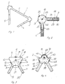
- Fig. 1 eine Draufsicht auf einen sich senkrecht zur Bildebene erstreckenden Träger mit zwei Profilstäben gemäß Fig. 4,
- Fign. 2 -4 drei Varianten von Profilstabquerschnitten, wobei in Fig. 2 noch zwei benachbarte Profilstäbe verbindende Tragwände teilweise dargestellt sind.
- 1 is a plan view of a beam extending perpendicular to the image plane with two profile bars according to FIG. 4,
- Fig. 2 -4 three variants of profile bar cross sections, with two adjacent profile bars supporting walls are partially shown in Fig. 2.
Der in Fig. 1 gezeigte Träger 1 besteht aus zwei Profilstäben 2 gleicher Querschnittsform, die über eine Tragwand 3 miteinander verbunden sind und von denen jeder mit einer weiteren Tragwand 4 bzw. 5 verbunden ist. Auf diese Weise entsteht ein Träger, des sen Form mit derjenigen eines Dreikantrohres vergleichbar ist. Der Übersichtlichkeit wegen sind die Querschnitte der Profilstäbe übertrieben groß dargestellt. Die in Fig. 1 eingezeichneten Profilstäbe entsprechen der Ausführungsform gemäß Fig. 4.The
Der in Fig. 3 gezeigte Profilstab besitzt einen Grundkörper 6, den man als trapezförmig oder etwa dreieckförmig bezeichnen kann. Mit diesem Grundkörper sind zwei winklig zueinander stehende Längsstege 7 und 8 verbunden, insbesondere einstückig hergestellt. Sie schließen einen spitzen Winkel 21 von beispielsweise etwa 60° ein.The profile bar shown in Fig. 3 has a base body 6, which can be described as trapezoidal or approximately triangular. With this base body two
An wenigstens einer, vorzugsweise aber allen drei Dreiecksflanken des dreikantförmigen Grundkörpers 6 befindet sich eine Lauffläche 12, 13, 14. Diese Laufflächen sind sowohl in dieser Figur als auch in den Figuren 2 und 4 der Deutlichkeit halber als erhabene Laufflächen dargestellt. Dies ist jedoch keinesfalls erforderlich, vielmehr kann es sich bei den Laufflächen um Teilflächen der Dreiecksflanken 9, 10, 11 handeln. Genauso ist es möglich, daß die Laufflächen durch rillenartige Vertiefungen in den Dreiecksflanken gebildet werden. Wichtig ist nur, daß sich die Normalen zu den Laufflächen bzw. gedachte senkrecht auf den Dreiecksflanken stehende, insbesondere durch die Laufflächenmitte gehende Längsebenen 15, 16, 17 in einer gemeinsamen Profillängsachse 18 schneiden. Weitere gedachte Längsmittelebenen 19 und 20 durch die beiden Stege 7 und 8 verlaufen ebenfalls durch die gemeinsame Profillängsachse. Dies ist unabhängig von der jeweiligen Querschnittsform des Profilstabs bzw. seines Grundkörpers 6 grundsätzlich der Fall, weswegen in allen drei Ausführungsbeispielen die gemeinsame Profillängsachse jeweils mit 18 bezeichnet ist.There is a
Beim Ausführungsbeispiel der Fig. 2 hat der Grundkörper 22 einen kreisförmigen Querschnitt, d.h. der Grundkörper hat die Gestalt eines Kreiszylinders. Dabei bilden beim Ausführungsbeispiel die beiden Längsstege 23 und 24 einen rechten oder auch kleineren Winkel. Lediglich beispielsweise sind drei Laufflächen 25, 26, 27 eingezeichnet.2, the
Die drei, in Fig. 1 lediglich schematisch dargestellten Tragwände 3, 4, 5 sind in Fig. 2 detaillierter gezeichnet. Jede besteht aus zwei parallelen dünnen plattenartigen Elementen 28 und 29 und einem sie verbindenden Waben- oder Hartschaumkern 30. Die plattenartigen Elemente überragen den Kern 30 vorzugsweise in Querrichtung des Profilstabs 2. Dadurch können sie mit ihren überstehenden Rändern an den beiden parallelen Außenflächen des in den Spaltraum zwischen den Elementen 28 und 29 eingreifenden Längsstegs 23 bzw. 24 befestigt werden. Der Profilstab der Fig. 2 ist als Ganzes mit 31 bezeichnet.The three supporting
In Fig. 4 ist ein drittes, bevorzugtes Ausführungsbeispiel eines Profilstabs dargestellt, der mit 2 bezeichnet ist. Er besitzt eine Querschnittsform, die man im wesentlichen wie folgt be schreiben kann. Sie besteht aus zwei mit ihren Trennflächen mittig aneinandergesetzten, unterschiedlich großen Sechseckhälften 33 und 34, wobei die Sechsecke über Eck durchtrennt wurden. Der Grundkörper 43 besteht demnach aus einer größeren und einer kleineren Sechskantprismenhälfte. Dabei verhalten sich die Eckmaße bzw. Umkreisdurchmesser der Sechsecke des größeren und kleineren Sechsecks etwa wie 2:1. An die Ecken der größeren Sechseckhälfte 34 sind die beiden Stege 36 und 37 angesetzt, insbesondere angeformt. Zur weiteren Gewichtsreduzierung kann die mittlere Sechseckfläche der größeren Sechseckhälfte gemäß Fig. 4 mit einer Hohlkehle 35 od. dgl. versehen sein. Aus der gleichen Überlegung heraus kann man auch die beiden freien Ecken 38, 39 der größeren Sechseckhälfte noch etwas abnehmen. Die gedanklich abgenommenen Teile sind teilweise durch strichpunktierte Linien und zum anderen Teil durch die tatsächlichen Umrißlinien in Fig. 4 eingezeichnet.4 shows a third, preferred exemplary embodiment of a profiled rod, which is designated by 2. It has a cross-sectional shape, which can be essentially as follows can write. It consists of two
Dieser Profilstab kann zum Beispiel und in bevorzugter Weise fünf Laufflächen 44 bis 48 aufweisen. Dabei bilden die Laufflächen 44 und 47 einerseits sowie 45 und 46 andererseits jeweils ein Laufflächenpaar für ein entsprechendes Radpaar oder Radpaare. Bei Verwendung zweier Profilstäbe dieser Art an einem Träger werden normalerweise nicht alle, sondern lediglich ein Teil der Laufflächen oder Laufflächenpaare benutzt, insbesondere die Laufflächen 44, 45, 48 am einen und 44, 47 oder 45, 46 am anderen Profilstab.This profile bar can have, for example and preferably five treads 44 to 48. The
Insbesondere aus Fig. 2 ersieht man, daß jeder Steg 23, 24 und die sich in Verlängerung anschließende ebene Tragwand 3, 4 in einer gemeinsamen Ebene liegen. Wenn die Tragwände nicht eben, sondern beispielsweise gewölbt, winkelförmig oder von ganz anderer Gestalt sind, so gilt auf jeden Fall, daß im Übergangsbereich vom Längssteg zum anschließenden Tragwandlängsbereich eine gemeinsame Ebene vorhanden sein muß. Anders ausgedrückt sollen beispielsweise bei einem ebenen Längssteg und einer ebenen Tragwand die Längsmittelebenen dieser beiden Elemente keinen Winkel einschließen. Nachdem der erfindungsgemäße Träger auch lediglich einem einzigen Profilstab und einer einzigen Tragwand bestehen kann, wobei der Profilstab aber auch in diesem Falle zwei Längsstege besitzt, ist leicht einzusehen, daß jedem dieser beiden Längsstege ein Längsrand der Tragwand zugeordnet ist oder sein kann. In diesem Falle könnte die Querschnittsform der Tragwand beispielsweise etwa C-förmig sein. Die Tragwand bestimmt in erster Linie die Schubsteifigkeit des Trägers, während die zur Lastenleitung dienenden Profilstäbe die Biegesteifigkeit des Trägers bestimmen. Die Tragfähigkeit des gesamten Trägers wird erst durch den Verbund beider Elemente erzielt.From Fig. 2 in particular it can be seen that each
Eine andere Variante eines Trägers kennzeichnet sich dadurch, daß jede Tragwand 3, 4, 5 aus einer dünnwandigen Platte und aus steifenden Elementen, insbesondere etwa parallel zum Profilstab 2, 31, 32 verlaufenden Längsrippen, Sicken u. dgl. besteht. Die Stärke der dünnwandigen Platte ist insbesondere geringer als die Dicke der Längsstege 7 und 8. Vorzugsweise beträgt sie etwa 0,3 bis 5 mm. Am Übergang zum zugeordneten Längssteg 7, 8 kann eine evtl. erforderliche Dickenanpassung vorgenommen werden.Another variant of a carrier is characterized in that each
Eine weitere Variante eines derartigen Trägers ist dadurch gekennzeichnet, daß jede Tragwand aus zwei dünnwandigen, durch Stege miteinander verbundenen Platten besteht, wobei die Stege insbesondere parallel zur Längsrichtung des Trägers verlaufen. Die dicke jeder dieser beiden Platten liegt vorzugsweise in der Größenordnung von 0,3 bis 1,5 mm. Dies ergibt dann eine GesamtDicke bis zu ca. 6 oder 8 mm. Diese Tragwand kann beispielsweise in der aus Fig. 2 ersichtlichen Weise mit dem zugeordneten Längssteg verbundenen werden. Auch im vorgenannten Falle kann eine Umfassung des Längsstegs vorgesehen sein, wobei dann der Endbereich der dünnwandigen Platte entsprechend formlich angepaßt werden muß.Another variant of such a carrier is characterized in that each support wall consists of two thin-walled plates which are connected to one another by webs, the webs in particular running parallel to the longitudinal direction of the carrier. The thickness of each of these two plates is preferably on the order of 0.3 to 1.5 mm. This then results in a total thickness of up to approx. 6 or 8 mm. This supporting wall can, for example, be connected to the associated longitudinal web in the manner shown in FIG. 2. In the aforementioned case, too, an encirclement of the longitudinal web can be provided, in which case the end region of the thin-walled plate must then be correspondingly adapted in shape.
Claims (13)
Priority Applications (1)
| Application Number | Priority Date | Filing Date | Title |
|---|---|---|---|
| AT86117285T ATE52296T1 (en) | 1986-01-29 | 1986-12-11 | CARRIER. |
Applications Claiming Priority (2)
| Application Number | Priority Date | Filing Date | Title |
|---|---|---|---|
| DE19863602575 DE3602575A1 (en) | 1986-01-29 | 1986-01-29 | CARRIER |
| DE3602575 | 1986-01-29 |
Publications (3)
| Publication Number | Publication Date |
|---|---|
| EP0230591A2 true EP0230591A2 (en) | 1987-08-05 |
| EP0230591A3 EP0230591A3 (en) | 1988-01-13 |
| EP0230591B1 EP0230591B1 (en) | 1990-04-25 |
Family
ID=6292836
Family Applications (1)
| Application Number | Title | Priority Date | Filing Date |
|---|---|---|---|
| EP86117285A Expired - Lifetime EP0230591B1 (en) | 1986-01-29 | 1986-12-11 | Girder |
Country Status (5)
| Country | Link |
|---|---|
| US (1) | US4829736A (en) |
| EP (1) | EP0230591B1 (en) |
| AT (1) | ATE52296T1 (en) |
| DE (1) | DE3602575A1 (en) |
| ES (1) | ES2014228B3 (en) |
Cited By (1)
| Publication number | Priority date | Publication date | Assignee | Title |
|---|---|---|---|---|
| CN103696535A (en) * | 2013-12-26 | 2014-04-02 | 南京工业大学 | Circular opening accessory with high utilization rate of corrugated web beam |
Families Citing this family (1)
| Publication number | Priority date | Publication date | Assignee | Title |
|---|---|---|---|---|
| US10190271B2 (en) * | 2015-10-13 | 2019-01-29 | University Of Notre Dame Du Lac | Adjustable modules for variable depth structures |
Citations (6)
| Publication number | Priority date | Publication date | Assignee | Title |
|---|---|---|---|---|
| FR1321943A (en) * | 1962-05-14 | 1963-03-22 | Ind De L Aluminium Sa | Lightweight metal crane |
| DE1169095B (en) * | 1961-11-11 | 1964-04-30 | Herbert Kasting | Box girder crane bridge for console trolley |
| US3488692A (en) * | 1967-02-08 | 1970-01-06 | Aisin Seiki | Transfer machine for die-cast products |
| US4416097A (en) * | 1976-02-20 | 1983-11-22 | Weir Richard L | Universal beam construction system |
| FR2530526A1 (en) * | 1982-07-23 | 1984-01-27 | Ind | Robot arm. |
| DE3313215A1 (en) * | 1983-04-13 | 1984-10-18 | Robert Bosch Gmbh, 7000 Stuttgart | Linear unit for handling devices for industrial production |
Family Cites Families (13)
| Publication number | Priority date | Publication date | Assignee | Title |
|---|---|---|---|---|
| US1527728A (en) * | 1920-06-28 | 1925-02-24 | Firm Luftschiffbau Zeppelin Gm | Hollow bar in two pieces |
| US2003738A (en) * | 1933-09-05 | 1935-06-04 | Cartwright Frank Poole | Fabricated structure and elements thereof |
| US3021014A (en) * | 1959-01-19 | 1962-02-13 | Link Belt Speeder Corp | Crane boom structure |
| CH389204A (en) * | 1961-05-19 | 1965-03-15 | Alusuisse | Overhead crane bridge made of light metal |
| US3256671A (en) * | 1962-09-13 | 1966-06-21 | Mc Graw Edison Co | Elongated rigid structure |
| US3273299A (en) * | 1963-07-12 | 1966-09-20 | Jr Philip F Hartung | Bipod components and building units containing same |
| DE1559408A1 (en) * | 1965-06-09 | 1969-08-28 | Rensch Eberhard | Framework |
| SE333050B (en) * | 1970-05-04 | 1971-03-01 | Linden Alimak Ab | |
| GB1555618A (en) * | 1976-05-05 | 1979-11-14 | Dziewolski R | Rigid assembly joint |
| US4171598A (en) * | 1977-10-21 | 1979-10-23 | J. I. Case Company | Hollow boom construction |
| DE8032320U1 (en) * | 1980-12-04 | 1981-04-02 | Liebherr-Werk Ehingen Gmbh, 7930 Ehingen | METAL CARRIER |
| FI73401C (en) * | 1981-08-18 | 1987-10-09 | Coles Cranes Ltd | BOM FOER LYFTKRAN ELLER LIKNANDE. |
| IT1163808B (en) * | 1983-07-19 | 1987-04-08 | Sadelmi Cogepi Cie Gen Progett | STRUCTURAL ELEMENT FOR METAL CARPENTRY AND STRUCTURES IN PARTICULAR SUPPORTS FOR AERIAL ELECTRICITY TRANSMISSION LINES WITH IT REALIZABLE |
-
1986
- 1986-01-29 DE DE19863602575 patent/DE3602575A1/en not_active Ceased
- 1986-12-11 EP EP86117285A patent/EP0230591B1/en not_active Expired - Lifetime
- 1986-12-11 ES ES86117285T patent/ES2014228B3/en not_active Expired - Lifetime
- 1986-12-11 AT AT86117285T patent/ATE52296T1/en not_active IP Right Cessation
-
1987
- 1987-01-20 US US07/005,237 patent/US4829736A/en not_active Expired - Fee Related
Patent Citations (6)
| Publication number | Priority date | Publication date | Assignee | Title |
|---|---|---|---|---|
| DE1169095B (en) * | 1961-11-11 | 1964-04-30 | Herbert Kasting | Box girder crane bridge for console trolley |
| FR1321943A (en) * | 1962-05-14 | 1963-03-22 | Ind De L Aluminium Sa | Lightweight metal crane |
| US3488692A (en) * | 1967-02-08 | 1970-01-06 | Aisin Seiki | Transfer machine for die-cast products |
| US4416097A (en) * | 1976-02-20 | 1983-11-22 | Weir Richard L | Universal beam construction system |
| FR2530526A1 (en) * | 1982-07-23 | 1984-01-27 | Ind | Robot arm. |
| DE3313215A1 (en) * | 1983-04-13 | 1984-10-18 | Robert Bosch Gmbh, 7000 Stuttgart | Linear unit for handling devices for industrial production |
Cited By (1)
| Publication number | Priority date | Publication date | Assignee | Title |
|---|---|---|---|---|
| CN103696535A (en) * | 2013-12-26 | 2014-04-02 | 南京工业大学 | Circular opening accessory with high utilization rate of corrugated web beam |
Also Published As
| Publication number | Publication date |
|---|---|
| ATE52296T1 (en) | 1990-05-15 |
| EP0230591A3 (en) | 1988-01-13 |
| EP0230591B1 (en) | 1990-04-25 |
| US4829736A (en) | 1989-05-16 |
| DE3602575A1 (en) | 1987-07-30 |
| ES2014228B3 (en) | 1990-07-01 |
Similar Documents
| Publication | Publication Date | Title |
|---|---|---|
| DE2147623C2 (en) | Wall, in particular side wall for truck beds | |
| DE69103257T2 (en) | STRUCTURAL SUPPORT. | |
| DE69832087T2 (en) | PLASTIC PALLET AND METHOD FOR MANUFACTURING SUCH PALLETS AND OTHER PLASTIC PRODUCTS | |
| DE69422292T2 (en) | UNIVERSAL CARRIER FOR A MOVING LOAD | |
| DE3304783C2 (en) | ||
| DE102012109586A1 (en) | Crane, in particular overhead crane or gantry crane, with at least two crane girders | |
| CH643907A5 (en) | I-SHAPED CARRIER PROFILE MADE OF LIGHT METAL. | |
| DE2547897A1 (en) | Extruded hollow girder with reinforcement insert - has steel strips in slots inside beam in regions of high tensile stress | |
| DE4100842C1 (en) | Coil spring with several concentric spring element turns - has symmetrical spring elements to attain coincidence of load and geometrical axes | |
| DE3644743A1 (en) | ROLLER BEARING STRAIGHT GUIDE | |
| EP0230591A2 (en) | Girder | |
| WO1994022621A1 (en) | Cutting insert | |
| EP0418640A1 (en) | Cage for a rolling bearing for longitudinal movements | |
| DE2225707A1 (en) | TWO-RAIL CONVEYOR SYSTEM | |
| DE102018133164A1 (en) | Cutting tool | |
| DE3535524C2 (en) | Cover for street shafts or inlets | |
| EP0997220A2 (en) | Tool holder for machine tool | |
| DE3340520C2 (en) | ||
| DE4106620A1 (en) | Support section for movable side carriage - has extruded profiled section with hard profiled rod engaging in groove | |
| DE4143352C2 (en) | Hollow profiled light metal bar | |
| EP0144494A1 (en) | Wheel load measuring device | |
| EP3095736A2 (en) | Conveyor line with conveyor belt supporting modules coupled to transverse members | |
| DE2804378C3 (en) | Flange connection between a vehicle axle and the longitudinal spars of a chassis | |
| DE4227599A1 (en) | LINEAR SLIDE BEARING | |
| EP4251494B1 (en) | Module block and module kit for providing a robot vehicle or logistics vehicle |
Legal Events
| Date | Code | Title | Description |
|---|---|---|---|
| PUAI | Public reference made under article 153(3) epc to a published international application that has entered the european phase |
Free format text: ORIGINAL CODE: 0009012 |
|
| AK | Designated contracting states |
Kind code of ref document: A2 Designated state(s): AT CH ES FR GB IT LI |
|
| PUAL | Search report despatched |
Free format text: ORIGINAL CODE: 0009013 |
|
| RHK1 | Main classification (correction) |
Ipc: E04C 3/00 |
|
| AK | Designated contracting states |
Kind code of ref document: A3 Designated state(s): AT CH ES FR GB IT LI |
|
| 17P | Request for examination filed |
Effective date: 19880229 |
|
| 17Q | First examination report despatched |
Effective date: 19890224 |
|
| ITF | It: translation for a ep patent filed | ||
| GRAA | (expected) grant |
Free format text: ORIGINAL CODE: 0009210 |
|
| AK | Designated contracting states |
Kind code of ref document: B1 Designated state(s): AT CH ES FR GB IT LI |
|
| REF | Corresponds to: |
Ref document number: 52296 Country of ref document: AT Date of ref document: 19900515 Kind code of ref document: T |
|
| GBT | Gb: translation of ep patent filed (gb section 77(6)(a)/1977) | ||
| ET | Fr: translation filed | ||
| ITTA | It: last paid annual fee | ||
| PLBE | No opposition filed within time limit |
Free format text: ORIGINAL CODE: 0009261 |
|
| STAA | Information on the status of an ep patent application or granted ep patent |
Free format text: STATUS: NO OPPOSITION FILED WITHIN TIME LIMIT |
|
| 26N | No opposition filed | ||
| REG | Reference to a national code |
Ref country code: CH Ref legal event code: PUE Owner name: VI WATERJET GMBH ROBOTERSYSTEME |
|
| REG | Reference to a national code |
Ref country code: GB Ref legal event code: 732E |
|
| REG | Reference to a national code |
Ref country code: FR Ref legal event code: TP |
|
| REG | Reference to a national code |
Ref country code: ES Ref legal event code: PC2A Owner name: VI WATERJET GMBH ROBOTERSYSTEME |
|
| PGFP | Annual fee paid to national office [announced via postgrant information from national office to epo] |
Ref country code: FR Payment date: 19941123 Year of fee payment: 9 |
|
| PGFP | Annual fee paid to national office [announced via postgrant information from national office to epo] |
Ref country code: CH Payment date: 19941125 Year of fee payment: 9 |
|
| PGFP | Annual fee paid to national office [announced via postgrant information from national office to epo] |
Ref country code: GB Payment date: 19941128 Year of fee payment: 9 |
|
| PGFP | Annual fee paid to national office [announced via postgrant information from national office to epo] |
Ref country code: AT Payment date: 19941129 Year of fee payment: 9 |
|
| PGFP | Annual fee paid to national office [announced via postgrant information from national office to epo] |
Ref country code: ES Payment date: 19941216 Year of fee payment: 9 |
|
| ITPR | It: changes in ownership of a european patent |
Owner name: CESSIONE;VI WATERJET GMBH ROBOTERSYSTEME |
|
| PG25 | Lapsed in a contracting state [announced via postgrant information from national office to epo] |
Ref country code: GB Effective date: 19951211 Ref country code: AT Effective date: 19951211 |
|
| PG25 | Lapsed in a contracting state [announced via postgrant information from national office to epo] |
Ref country code: ES Free format text: LAPSE BECAUSE OF EXPIRATION OF PROTECTION Effective date: 19951212 |
|
| PG25 | Lapsed in a contracting state [announced via postgrant information from national office to epo] |
Ref country code: LI Effective date: 19951231 Ref country code: CH Effective date: 19951231 |
|
| GBPC | Gb: european patent ceased through non-payment of renewal fee |
Effective date: 19951211 |
|
| REG | Reference to a national code |
Ref country code: CH Ref legal event code: PL |
|
| PG25 | Lapsed in a contracting state [announced via postgrant information from national office to epo] |
Ref country code: FR Effective date: 19960830 |
|
| REG | Reference to a national code |
Ref country code: FR Ref legal event code: ST |
|
| REG | Reference to a national code |
Ref country code: ES Ref legal event code: FD2A Effective date: 20010301 |
|
| PG25 | Lapsed in a contracting state [announced via postgrant information from national office to epo] |
Ref country code: IT Free format text: LAPSE BECAUSE OF NON-PAYMENT OF DUE FEES;WARNING: LAPSES OF ITALIAN PATENTS WITH EFFECTIVE DATE BEFORE 2007 MAY HAVE OCCURRED AT ANY TIME BEFORE 2007. THE CORRECT EFFECTIVE DATE MAY BE DIFFERENT FROM THE ONE RECORDED. Effective date: 20051211 |