EP0230579A1 - Particle filter for waste gases - Google Patents
Particle filter for waste gases Download PDFInfo
- Publication number
- EP0230579A1 EP0230579A1 EP86116939A EP86116939A EP0230579A1 EP 0230579 A1 EP0230579 A1 EP 0230579A1 EP 86116939 A EP86116939 A EP 86116939A EP 86116939 A EP86116939 A EP 86116939A EP 0230579 A1 EP0230579 A1 EP 0230579A1
- Authority
- EP
- European Patent Office
- Prior art keywords
- fibers
- filter
- winding
- wound
- auxiliary
- Prior art date
- Legal status (The legal status is an assumption and is not a legal conclusion. Google has not performed a legal analysis and makes no representation as to the accuracy of the status listed.)
- Withdrawn
Links
Images


Classifications
-
- B—PERFORMING OPERATIONS; TRANSPORTING
- B29—WORKING OF PLASTICS; WORKING OF SUBSTANCES IN A PLASTIC STATE IN GENERAL
- B29C—SHAPING OR JOINING OF PLASTICS; SHAPING OF MATERIAL IN A PLASTIC STATE, NOT OTHERWISE PROVIDED FOR; AFTER-TREATMENT OF THE SHAPED PRODUCTS, e.g. REPAIRING
- B29C53/00—Shaping by bending, folding, twisting, straightening or flattening; Apparatus therefor
- B29C53/56—Winding and joining, e.g. winding spirally
- B29C53/58—Winding and joining, e.g. winding spirally helically
- B29C53/583—Winding and joining, e.g. winding spirally helically for making tubular articles with particular features
- B29C53/587—Winding and joining, e.g. winding spirally helically for making tubular articles with particular features having a non-uniform wall-structure, e.g. with inserts, perforations, locally concentrated reinforcements
-
- B—PERFORMING OPERATIONS; TRANSPORTING
- B01—PHYSICAL OR CHEMICAL PROCESSES OR APPARATUS IN GENERAL
- B01D—SEPARATION
- B01D39/00—Filtering material for liquid or gaseous fluids
- B01D39/14—Other self-supporting filtering material ; Other filtering material
- B01D39/20—Other self-supporting filtering material ; Other filtering material of inorganic material, e.g. asbestos paper, metallic filtering material of non-woven wires
- B01D39/2003—Glass or glassy material
- B01D39/2017—Glass or glassy material the material being filamentary or fibrous
-
- B—PERFORMING OPERATIONS; TRANSPORTING
- B01—PHYSICAL OR CHEMICAL PROCESSES OR APPARATUS IN GENERAL
- B01D—SEPARATION
- B01D39/00—Filtering material for liquid or gaseous fluids
- B01D39/14—Other self-supporting filtering material ; Other filtering material
- B01D39/20—Other self-supporting filtering material ; Other filtering material of inorganic material, e.g. asbestos paper, metallic filtering material of non-woven wires
- B01D39/2027—Metallic material
- B01D39/2041—Metallic material the material being filamentary or fibrous
-
- B—PERFORMING OPERATIONS; TRANSPORTING
- B01—PHYSICAL OR CHEMICAL PROCESSES OR APPARATUS IN GENERAL
- B01D—SEPARATION
- B01D39/00—Filtering material for liquid or gaseous fluids
- B01D39/14—Other self-supporting filtering material ; Other filtering material
- B01D39/20—Other self-supporting filtering material ; Other filtering material of inorganic material, e.g. asbestos paper, metallic filtering material of non-woven wires
- B01D39/2068—Other inorganic materials, e.g. ceramics
- B01D39/2082—Other inorganic materials, e.g. ceramics the material being filamentary or fibrous
-
- B—PERFORMING OPERATIONS; TRANSPORTING
- B01—PHYSICAL OR CHEMICAL PROCESSES OR APPARATUS IN GENERAL
- B01D—SEPARATION
- B01D46/00—Filters or filtering processes specially modified for separating dispersed particles from gases or vapours
- B01D46/24—Particle separators, e.g. dust precipitators, using rigid hollow filter bodies
-
- B—PERFORMING OPERATIONS; TRANSPORTING
- B29—WORKING OF PLASTICS; WORKING OF SUBSTANCES IN A PLASTIC STATE IN GENERAL
- B29C—SHAPING OR JOINING OF PLASTICS; SHAPING OF MATERIAL IN A PLASTIC STATE, NOT OTHERWISE PROVIDED FOR; AFTER-TREATMENT OF THE SHAPED PRODUCTS, e.g. REPAIRING
- B29C70/00—Shaping composites, i.e. plastics material comprising reinforcements, fillers or preformed parts, e.g. inserts
- B29C70/04—Shaping composites, i.e. plastics material comprising reinforcements, fillers or preformed parts, e.g. inserts comprising reinforcements only, e.g. self-reinforcing plastics
- B29C70/06—Fibrous reinforcements only
- B29C70/10—Fibrous reinforcements only characterised by the structure of fibrous reinforcements, e.g. hollow fibres
- B29C70/16—Fibrous reinforcements only characterised by the structure of fibrous reinforcements, e.g. hollow fibres using fibres of substantial or continuous length
- B29C70/20—Fibrous reinforcements only characterised by the structure of fibrous reinforcements, e.g. hollow fibres using fibres of substantial or continuous length oriented in a single direction, e.g. roofing or other parallel fibres
- B29C70/205—Fibrous reinforcements only characterised by the structure of fibrous reinforcements, e.g. hollow fibres using fibres of substantial or continuous length oriented in a single direction, e.g. roofing or other parallel fibres the structure being shaped to form a three-dimensional configuration
- B29C70/207—Fibrous reinforcements only characterised by the structure of fibrous reinforcements, e.g. hollow fibres using fibres of substantial or continuous length oriented in a single direction, e.g. roofing or other parallel fibres the structure being shaped to form a three-dimensional configuration arranged in parallel planes of fibres crossing at substantial angles
-
- F—MECHANICAL ENGINEERING; LIGHTING; HEATING; WEAPONS; BLASTING
- F01—MACHINES OR ENGINES IN GENERAL; ENGINE PLANTS IN GENERAL; STEAM ENGINES
- F01N—GAS-FLOW SILENCERS OR EXHAUST APPARATUS FOR MACHINES OR ENGINES IN GENERAL; GAS-FLOW SILENCERS OR EXHAUST APPARATUS FOR INTERNAL COMBUSTION ENGINES
- F01N3/00—Exhaust or silencing apparatus having means for purifying, rendering innocuous, or otherwise treating exhaust
- F01N3/02—Exhaust or silencing apparatus having means for purifying, rendering innocuous, or otherwise treating exhaust for cooling, or for removing solid constituents of, exhaust
- F01N3/021—Exhaust or silencing apparatus having means for purifying, rendering innocuous, or otherwise treating exhaust for cooling, or for removing solid constituents of, exhaust by means of filters
- F01N3/022—Exhaust or silencing apparatus having means for purifying, rendering innocuous, or otherwise treating exhaust for cooling, or for removing solid constituents of, exhaust by means of filters characterised by specially adapted filtering structure, e.g. honeycomb, mesh or fibrous
- F01N3/0226—Exhaust or silencing apparatus having means for purifying, rendering innocuous, or otherwise treating exhaust for cooling, or for removing solid constituents of, exhaust by means of filters characterised by specially adapted filtering structure, e.g. honeycomb, mesh or fibrous the structure being fibrous
-
- B—PERFORMING OPERATIONS; TRANSPORTING
- B01—PHYSICAL OR CHEMICAL PROCESSES OR APPARATUS IN GENERAL
- B01D—SEPARATION
- B01D2239/00—Aspects relating to filtering material for liquid or gaseous fluids
- B01D2239/06—Filter cloth, e.g. knitted, woven non-woven; self-supported material
- B01D2239/0604—Arrangement of the fibres in the filtering material
- B01D2239/0636—Two or more types of fibres present in the filter material
-
- B—PERFORMING OPERATIONS; TRANSPORTING
- B01—PHYSICAL OR CHEMICAL PROCESSES OR APPARATUS IN GENERAL
- B01D—SEPARATION
- B01D2239/00—Aspects relating to filtering material for liquid or gaseous fluids
- B01D2239/06—Filter cloth, e.g. knitted, woven non-woven; self-supported material
- B01D2239/065—More than one layer present in the filtering material
-
- B—PERFORMING OPERATIONS; TRANSPORTING
- B01—PHYSICAL OR CHEMICAL PROCESSES OR APPARATUS IN GENERAL
- B01D—SEPARATION
- B01D2239/00—Aspects relating to filtering material for liquid or gaseous fluids
- B01D2239/06—Filter cloth, e.g. knitted, woven non-woven; self-supported material
- B01D2239/069—Special geometry of layers
- B01D2239/0695—Wound layers
-
- B—PERFORMING OPERATIONS; TRANSPORTING
- B29—WORKING OF PLASTICS; WORKING OF SUBSTANCES IN A PLASTIC STATE IN GENERAL
- B29L—INDEXING SCHEME ASSOCIATED WITH SUBCLASS B29C, RELATING TO PARTICULAR ARTICLES
- B29L2031/00—Other particular articles
- B29L2031/14—Filters
-
- Y—GENERAL TAGGING OF NEW TECHNOLOGICAL DEVELOPMENTS; GENERAL TAGGING OF CROSS-SECTIONAL TECHNOLOGIES SPANNING OVER SEVERAL SECTIONS OF THE IPC; TECHNICAL SUBJECTS COVERED BY FORMER USPC CROSS-REFERENCE ART COLLECTIONS [XRACs] AND DIGESTS
- Y02—TECHNOLOGIES OR APPLICATIONS FOR MITIGATION OR ADAPTATION AGAINST CLIMATE CHANGE
- Y02T—CLIMATE CHANGE MITIGATION TECHNOLOGIES RELATED TO TRANSPORTATION
- Y02T10/00—Road transport of goods or passengers
- Y02T10/10—Internal combustion engine [ICE] based vehicles
- Y02T10/12—Improving ICE efficiencies
Definitions
- the invention relates to a particle filter for exhaust gases, consisting of a winding body made of temperature-resistant fibers.
- the various filter constructions such as ceramic foam, fiber mats, wire mesh and as a winding body
- the latter have the advantage over the previous variants that the ratio of the filter size to the filter effect is more favorable, i.e. is lower than with filters of other constructions.
- the invention has for its object to improve a filter of the type mentioned in such a way that the filter effect of the filter material can be used as fully as possible.
- part of the fibers namely the auxiliary fibers, serves, in addition to the function as a filter, as a framework for the winding body, so that support bodies can be dispensed with. This eliminates any impairment of the degree of separation of the filter.
- a homogeneous structure that can be achieved in this way creates a homogeneous flow field during operation, which enables the particles to be deposited evenly through the entire filter.
- Another advantage of the filter according to the invention is that a uniform filter can be produced, which can be flowed through either in one direction or in the other direction as required.
- the basic fibers can be rovings or yarns made of ceramic, quartz, silicon, glass or similar temperature-resistant materials, the filaments of the rovings or yarns being able to have extremely small cross sections, so that the effective area of the filter can be increased by the choice correspondingly thin filaments can be effected.
- the filaments of the basic fibers preferably have a diameter of at most 10 ⁇ m, preferably less than 7 ⁇ m.
- Steel wire which has a diameter of 0.1 to 0.7 mm depending on the type of use or the quantity ratio in the filter body, can preferably be used as the auxiliary fiber.
- the wire thickness is inversely proportional to the ratio of the amount of wire to the amount of basic fibers in the filter body.
- the basic fibers and the auxiliary fibers can be combined according to different patterns.
- the filter body consisting essentially of basic fibers is mixed with the auxiliary fibers.
- This can be done by winding the auxiliary fibers together with the basic fibers in one operation, in which, depending on the desired quantitative ratio, an auxiliary fiber and several basic fiber strands are wound simultaneously.
- the auxiliary fibers are located essentially on the surfaces of the filter body, predominantly basic fibers being provided between the two layers of auxiliary fibers.
- the auxiliary fibers can either be wound or used in the form of a network.
- This embodiment has the advantage that the auxiliary fibers anchor the basic fibers, which can tear at least on the surface because of their reduced cross-section and possibly because of their porosity.
- the required stiffness is determined by appropriate selection of the quantity or the thickness of the auxiliary fibers introduced in such a way that the filter body, which consists solely of basic fibers and auxiliary fibers, on its own, i.e. is operational without support elements.
- the auxiliary fibers are an integral part of the filter body or the filter material.
- the filter according to the invention can take on any geometric shape that can be produced in the winding process. It is thus possible to design the filter in the form of a plate as well as a tube.
- the fibers in the winding body are wound in an intersecting manner, it being possible, in particular by using an open winding process, to create spaces between fiber strands which give the winding body the porosity required for the flow and deflection of the gas to be cleaned.
- the particles can flow partially through different layers and within the Deposit the winding body, whereby a depth filter effect is achieved.
- This effect can be intensified by measures which reduce the knotting of crossing fiber or yarn strands. It is also advantageous if at least the basic fibers are loosely guided when the filter is being wound in order to introduce a corresponding porosity into the filter, which brings about a depth filter effect.
- the invention extends to a method for producing a particle filter, which is characterized by the features of claims 12-14.
- Fiber strands are to be understood as the basic fibers and the auxiliary fibers.
- gaps are provided which allow particles with the gas to penetrate into the inner regions of the filter. In this way, not only the surface, but the entire filter volume acts as a deposit area for the particles contained in the gas.
- the gaps must be designed so that the exhaust gases undergo multiple deflections and in this way particles that have not been held on the surface or the first layers can be retained in deeper layers.
- the porosity is preferably achieved by simultaneously winding a plurality of fiber strands which are wound in cross layers at a distance from one another.
- the fibers of a next layer are laid over several fibers of the previous layer without creating nodes.
- This has the advantage that an intermediate layer is the two adjacent ones can separate fiber layers crossing at a distance that corresponds approximately to the fiber strand thickness.
- This is achieved in a technically simple manner by using a ring thread eye.
- the number of fiber strands guided with the ring thread eye depends on the diameter of the winding former and on the desired distance between the fiber strands.
- Each winding layer will consist exclusively of fibers lying next to each other, ie without knots.
- the fibers of different layers with the same orientation are wound on the hatch to avoid pore channels that run straight through the winding body wall. This creates zigzag channels through which the gas can flow with particles and particles can accumulate again and again.
- a plurality of filters can be wound in one operation by winding a correspondingly long filter body and separating them into the filter bodies one after the other. Working time and material loss are reduced.
- the fiber strands can be rovings combined from many thin filaments, the cross section of an filament being preferably less than 10 ⁇ m thick.
- Such a fiber strand has the advantage that the deposition area for the particles is greatly increased by the large number of very thin filaments. Their effect is particularly noticeable when the fiber is loosely wound so that the gas with small particles can also flow through fiber strands. In this regard, a larger diameter is also advantageous for tubular filters.
- auxiliary fibers are wound with the other fibers, so that the filter body is evenly interspersed with auxiliary fibers.
- the auxiliary fiber winding or network also serves as filter material on which the particles can be deposited, just like with the other fibers.
- the filter bodies can be wound using any method known in winding technology.
- 1 shows, for example, a thread eye (10) with three fiber strands (11) arranged next to one another, which are wound around a mandrel (12) rotating about the axis.
- the fiber strands (11) are each held at intervals (13) so that a width (14) is coated per winding which is greater than the sum of the diameters of the three fibers.
- the first winding layer (15) is placed approximately at an angle of 60 °.
- a second layer is laid crosswise at minus 60 °.
- a third layer can then in turn receive a different orientation that does not correspond to either the first or the second layer. If the third layer is also to be laid at 60 ° like the first layer, then the fiber strands are placed on the hatch in relation to the previous layer of the same orientation on the hatch, as shown in broken lines under the reference number (16).
- FIG. 2 The result of such a winding pattern is shown in FIG. 2 as a greatly enlarged detail, the fibers of different orientations being drawn at right angles to simplify the illustration.
- the fibers (20) wound at a distance and on the hatch form pore chambers (21), all of which are connected to one another, but do not form any openings crossing the filter wall in a straight line.
- An exhaust gas stream (22) is therefore guided in a zigzag fashion within these chambers (21) or channels, which on the one hand are large enough to let the particles in the gas (22) pass and on the other hand are small enough to allow these particles to pass through the filter (23) with the To be able to hold fibers (20).
- the effective filtering surface thus extends to the surface of all fiber strands (11 or 20) of the filter body.
- a fiber strand (11) consists of several filaments (18) which are bundled together to form a fiber strand or roving (11).
- the fiber strands (20) consist of filaments (24) twisted into a yarn.
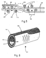
- FIG 3 shows an example in which a tubular filter (39) is wound using a ring thread eye (30).
- the ring thread eye (30) has six bores (31), through each of which a fiber strand (32) is guided, which are guided over castors (33).
- the number of fiber strands (32) to be wound together depends on the desired distance (13, FIG. 1) between the fiber strands (32) on the winding body (39) and the diameter of the winding body (39).
- the mandrel consists of a mandrel core (37) around which sleeve segments (38) are placed.
- the fiber strands (32) are wound onto the sleeve segments (38) by rotating the mandrel (37, 38) in the direction of the arrow and displacing the ring thread eye (30) in the axial direction.
- the winding angle is determined via the resulting speed, which results from the combination of the speed of rotation of the mandrel and the feed of the thread eye.
- the angles are chosen so that the fibers of each layer cross with the fibers of the adjacent fibers.
- Another parameter to consider is the fiber draw during the winding process.
- FIG. 4 shows a plate-shaped filter (100) designed as a winding body and shown in cross section, which consists of basic fibers (110 and 120) made of ceramic, glass or similar temperature-resistant material and of auxiliary fibers (130) made of steel or another temperature-resistant metal .
- the basic fibers (110 and 120) are fiber strands, each of which contains several filaments (140) with a very small diameter in the range of a few ⁇ m.
- the filaments (140) can be arranged parallel to each other to form a roving or twisted to form a yarn.
- the auxiliary fibers (130) are metal wires which are coiled during the winding process of the basic fibers (110 and 120) and thereby penetrate the filter (100) in all layers.
- the formation of the pore chambers can be illustrated using FIG. 5.
- the basic fiber strands (110 and 120) are yarns spun from filaments (140).
- three basic fibers are wound simultaneously in the winding process so that they come to lie next to one another with the appropriate spacing (150).
- the transverse base fibers (120) each lie in the different layers on the longitudinal fibers (110) and form pore chambers (200), as shown in the left half of FIG. 5. In transition areas (210) there is a change of position between fibers of different orientations.
- knots (210) the fiber spacings of different layers are reduced, so that the formation of pore chambers is effectively prevented. It is therefore advisable to run as many fibers as possible in the winding process in order to reduce the nodes (210).
- the exhaust gas (220) flows through the loose meshwork with numerous deflections and in part carries the particles with it into the interior of the filter (100).
- the particles meet fibers (110 to 130) one after the other and are deposited there.
- the filtration is therefore not carried out on the surface of the filter, but rather total volume or the sum of the surfaces of the fibers (110 to 130) or the filaments (140) contributes to the filtration of the gas particles.
- the basic fibers (110 and 120) make up the major part of the filter effect, they are wound in a symmetrical form, while the auxiliary fibers (130) are placed within the gaps (150).
- auxiliary fibers (130) in the filter There are many ways to integrate the auxiliary fibers (130) in the filter. These can be integrated homogeneously in the winding body or can also be attached to a greater extent in a filter plane or on the surfaces of the filter.
- FIG. 6 shows an embodiment in the case of a tubular filter (101) in which the auxiliary fibers (131) are arranged on the inner circumference and on the outer circumference of the tubular body, while the inner region of the filter tube (101) contains only basic fibers (111, 121).
- the auxiliary fibers (131) are processed into networks (300) according to FIG. 6.
- the auxiliary fibers on the outer circumference serve not only as filter material and to stiffen the winding body, but also to protect and anchor the surface base fibers. Particularly in the case of brittle and very thin base fibers (111, 121), these can easily tear due to handling etc., in particular on the surface of the winding body.
- peripheral auxiliary fibers (131), which can also be wound, do not represent a barrier, but rather a filter part. If necessary, additional fibers can be provided in the basic fiber winding body, for example in the manner shown in FIG. 4.
- Filters of the type described here are direction-independent, so that a uniform filter can be produced for both gas flow directions.
- the filter effect is, for example, the same, regardless of whether the gas is directed from the inside to the outside or from the outside to the inside of the filter tube (101).
Abstract
Description
Die Erfindung bezieht sich auf einen Partikelfilter für Abgase, bestehend aus einem Wickelkörper aus temperaturbeständigen Fasern.The invention relates to a particle filter for exhaust gases, consisting of a winding body made of temperature-resistant fibers.
Unter den verschiedenen Filterkonstruktionen, wie aus Keramikschaum, Fasermatten, Drahtgestrick und als Wickelkörper haben die letzteren gegenüber den vorherstehenden Varianten den Vorteil, daß das Verhältnis der Filterbaugröße zur Filterwirkung günstiger, d.h. geringer ist als bei Filtern anderer Konstruktionen.Among the various filter constructions, such as ceramic foam, fiber mats, wire mesh and as a winding body, the latter have the advantage over the previous variants that the ratio of the filter size to the filter effect is more favorable, i.e. is lower than with filters of other constructions.
Um diesen Vorteil besonders deutlich zu machen, müssen Fasern mit Elementarfasern möglichst geringer Faserdicke im Bereich von einigen µm verwendet werden. Weiterhin ist auf eine möglichst lockere Bewicklung zu achten, die eine Tiefenfiltrierung von Partikeln erlaubt.In order to make this advantage particularly clear, fibers with elementary fibers with the smallest possible fiber thickness in the range of a few μm must be used. Furthermore, care should be taken to ensure that the wrapping is as loose as possible, which allows deep filtration of particles.
Ein derartiger Wickelkörper besitzt aber keine ausreichende Steifigkeit, die einen Einsatz des Wickelkörpers als Filter ohne Stützeinrichtung erlaubt. Aus Wickelkörpern bestehende Filter werden daher, wie aus der DE-PS 30 07 642 bekannt, auf Stützrohren aufgewickelt, die mit Durchgangsöffnungen versehen sind.However, such a winding body does not have sufficient rigidity, which allows the winding body to be used as a filter without a support device. Filters consisting of winding bodies are therefore, as is known from DE-PS 30 07 642, wound on support tubes which are provided with through-openings.
Bei der bekannten Einrichtung strömen die Abgase im Betrieb des Filters in radialer Richtung in das Filterrohr ein und verlassen es in axialer Richtung. Die im Abgas enthaltenen Partikel werden dabei am Wickelkörper festgehalten. Es hat sich jedoch gezeigt, daß aufgrund der unterschiedlichen Strömungskonfigurationen zwischen Filtermaterial und Stützkörper sich die Abgase unregelmäßig ablagern. Der Abscheidegrad des Filters wird hierdurch stark beeinträchtigt.In the known device, the exhaust gases flow into the filter tube in the radial direction during operation of the filter and leave it in the axial direction. The particles contained in the exhaust gas are held on the winding body. However, it has been shown that due to the different flow configurations between filter material and The exhaust gas deposits irregularly. This severely affects the degree of separation of the filter.
Der Erfindung liegt die Aufgabe zugrunde, einen Filter der eingangs genannten Art dahingehend zu verbessern, daß die dem Filtermaterial eigene Filterwirkung möglichst voll genutzt werden kann.The invention has for its object to improve a filter of the type mentioned in such a way that the filter effect of the filter material can be used as fully as possible.
Die Aufgabe wird erfindungsgemäß durch die im Anspruch 1 gekennzeichneten Merkmale gelöst.The object is achieved by the features characterized in
Hierbei dient ein Teil der Fasern, nämlich die Hilfsfasern, neben der Funktion als Filter, als Gerüst für den Wickelkörper, so daß von Stützkörpern abgesehen werden kann. Es entfällt damit jede Beeinträchtigung des Abscheidegrades des Filters.Here, part of the fibers, namely the auxiliary fibers, serves, in addition to the function as a filter, as a framework for the winding body, so that support bodies can be dispensed with. This eliminates any impairment of the degree of separation of the filter.
Durch eine damit erreichbare homogene Struktur baut sich im Betrieb ein homogenes Strömungsfeld auf, das eine gleichmäßige Ablagerung der Partikel durch den gesamten Filter ermöglicht.A homogeneous structure that can be achieved in this way creates a homogeneous flow field during operation, which enables the particles to be deposited evenly through the entire filter.
Ein weiterer Vorteil des erfindungsgemäßen Filters liegt darin, daß ein einheitlicher Filter herstellbar ist, der je nach Bedarf entweder in der einen oder in der anderen Richtung durchströmbar ist.Another advantage of the filter according to the invention is that a uniform filter can be produced, which can be flowed through either in one direction or in the other direction as required.
Als Grundfasern können Rovings oder Garne aus Keramik, Quarz, Silizium, Glas oder ähnlichen temperaturbeständigen Materialien sein, wobei die Elementarfäden der Rovings oder Garne äußerst kleine Querschnitte haben können, so daß eine Erhöhung der Wirkfläche des Filters durch die Wahl entsprechend dünner Elementarfäden bewirkt werden kann.The basic fibers can be rovings or yarns made of ceramic, quartz, silicon, glass or similar temperature-resistant materials, the filaments of the rovings or yarns being able to have extremely small cross sections, so that the effective area of the filter can be increased by the choice correspondingly thin filaments can be effected.
Die Elementarfäden der Grundfasern haben vorzugsweise einen Durchmesser von höchstens 10 µm, vorzugsweise unter 7 µm.The filaments of the basic fibers preferably have a diameter of at most 10 µm, preferably less than 7 µm.
Als Hilfsfaser kann vorzugsweise Stahldraht verwendet werden, der je nach Art der Verwendung bzw. Mengenverhältnis im Filterkörper einen Durchmesser von 0,1 bis 0,7 mm hat. Die Drahtdicke verhält sich dabei umgekehrt proportional zum Verhältnis der Drahtmenge zur Grundfasermenge im Filterkörper. Die Grundfasern und die Hilfsfasern können nach verschiedenen Mustern kombiniert werden.Steel wire, which has a diameter of 0.1 to 0.7 mm depending on the type of use or the quantity ratio in the filter body, can preferably be used as the auxiliary fiber. The wire thickness is inversely proportional to the ratio of the amount of wire to the amount of basic fibers in the filter body. The basic fibers and the auxiliary fibers can be combined according to different patterns.
Gemäß einer Ausführung der Erfindung ist der im wesentlichen aus Grundfasern bestehende Filterkörper mit den Hilfsfasern versetzt. Dieses kann dadurch geschehen, daß die Hilfsfasern zusammen mit den Grundfasern in einem Arbeitsgang gewickelt werden, in dem je nach gewünschtem Mengenverhältnis eine Hilfsfaser und mehrere Grundfaserstränge gleichzeitig verwickelt werden. Dadurch ergibt sich eine gleichmäßige Verteilung von Hilfsfasern innerhalb des Filterkörpers. Es ist aber auch möglich, die Verteilung der Hilfsfasern beliebig zu wählen, indem zum Beispiel an den Außenschichten mehr Hilfsfasern eingebracht werden als in der Innenschicht.According to one embodiment of the invention, the filter body consisting essentially of basic fibers is mixed with the auxiliary fibers. This can be done by winding the auxiliary fibers together with the basic fibers in one operation, in which, depending on the desired quantitative ratio, an auxiliary fiber and several basic fiber strands are wound simultaneously. This results in an even distribution of auxiliary fibers within the filter body. However, it is also possible to choose the distribution of the auxiliary fibers as desired, for example by introducing more auxiliary fibers on the outer layers than in the inner layer.
Gemäß einer weiteren Ausgestaltung der Erfindung befinden sich die Hilfsfasern im wesentlichen an den Oberflächen des Filterkörpers, wobei zwischen den beiden Lagen mit Hilfsfasern vorwiegend Grundfasern vorgesehen sind. Hierbei lassen sich die Hilfsfasern entweder wickeln oder in der Form eines Netzwerkes verwenden.According to a further embodiment of the invention, the auxiliary fibers are located essentially on the surfaces of the filter body, predominantly basic fibers being provided between the two layers of auxiliary fibers. The auxiliary fibers can either be wound or used in the form of a network.
Diese Ausführung hat den Vorteil, daß die Hilfsfasern die Grundfasern verankern, die nämlich aufgrund ihres reduzierten Querschnittes und gegebenenfalls aufgrund ihrer Porosität zumindest an der Oberfläche reißen können.This embodiment has the advantage that the auxiliary fibers anchor the basic fibers, which can tear at least on the surface because of their reduced cross-section and possibly because of their porosity.
Selbstverständlich ist es auch möglich, beide Ausführungen zu kombinieren, d.h. Hilfsfasern an den Oberflächen des Filterkörpers vorzusehen und zusätzlich Hilfsfasern durch den Wickelaufbau der Grundfasern durchzuziehen.Of course, it is also possible to combine both versions, i.e. Provide auxiliary fibers on the surfaces of the filter body and pull additional auxiliary fibers through the winding structure of the basic fibers.
Unabhängig vom jeweils gewählten Muster wird die erforderliche Steifigkeit durch entsprechende Wahl der eingebrachten Menge bzw. der Dicke der Hilfsfasern bestimmt derart, daß der lediglich aus Grundfasern und Hilfsfasern bestehende Filterkörper für sich alleine, d.h. ohne Stützelemente einsatzfähig ist. Die Hilfsfasern sind dabei ein integraler Bestandteil des Filterkörpers bzw. des Filtermaterials.Regardless of the pattern chosen in each case, the required stiffness is determined by appropriate selection of the quantity or the thickness of the auxiliary fibers introduced in such a way that the filter body, which consists solely of basic fibers and auxiliary fibers, on its own, i.e. is operational without support elements. The auxiliary fibers are an integral part of the filter body or the filter material.
Der erfindungsgemäße Filter kann jede geometrische Form annehmen, die im Wickelverfahren herstellbar ist. So ist es möglich, den Filter sowohl platten- als auch rohrförmig auszubilden.The filter according to the invention can take on any geometric shape that can be produced in the winding process. It is thus possible to design the filter in the form of a plate as well as a tube.
Nach einer weiteren Ausgestaltung der Erfindung sind die Fasern im Wickelkörper sich kreuzend gewickelt, wobei insbesondere durch Verwendung eines offenen Wickelvorganges Zwischenräume zwischen Fasersträngen geschaffen werden können, die dem Wickelkörper eine für die Durchströmung und Umlenkung des zu reinigenden Gases erforderliche Porosität verleihen. Hierdurch können die Partikel zum Teil durch unterschiedliche Lagen strömen und sich innerhalb des Wickelkörpers ablagern, wodurch eine Tiefenfilterwirkung erreicht wird.According to a further embodiment of the invention, the fibers in the winding body are wound in an intersecting manner, it being possible, in particular by using an open winding process, to create spaces between fiber strands which give the winding body the porosity required for the flow and deflection of the gas to be cleaned. As a result, the particles can flow partially through different layers and within the Deposit the winding body, whereby a depth filter effect is achieved.
Dieser Effekt läßt sich durch Maßnahmen verstärken, die die Verknotungen von sich kreuzenden Faser- bzw. Garnsträngen vermindern. Es ist ferner vorteilhaft, wenn beim Wickeln des Filters zumindest die Grundfasern locker geführt werden, um eine entsprechende Porosität in den Filter einzubringen, die eine Tiefenfilterwirkung herbeiführt.This effect can be intensified by measures which reduce the knotting of crossing fiber or yarn strands. It is also advantageous if at least the basic fibers are loosely guided when the filter is being wound in order to introduce a corresponding porosity into the filter, which brings about a depth filter effect.
Die Erfindung erstreckt sich auf ein Verfahren zur Herstellung eines Partikelfilters, das durch die Merkmale aus den Ansprüchen 12 - 14 gekennzeichnet ist. Unter Fasersträngen sind die Grundfasern und die Hilfsfasern zu verstehen.The invention extends to a method for producing a particle filter, which is characterized by the features of claims 12-14. Fiber strands are to be understood as the basic fibers and the auxiliary fibers.
Beim Wickeln des Filters werden Lücken vorgesehen, die das Eindringen von Partikeln mit dem Gas in die inneren Bereiche des Filters ermöglichen. Auf diese Weise wirkt nicht nur die Oberfläche, sondern das gesamte Filtervolumen als Ablagerungsfläche für die im Gas enthaltenen Partikeln. Die Lücken müssen dabei so gestaltet sein, daß die Abgase mehrfache Umlenkungen erfahren und auf diese Weise Partikel, die nicht an der Oberfläche bzw. den ersten Schichten festgehalten wurden, in tieferen Schichten festgehalten werden können.When the filter is wound, gaps are provided which allow particles with the gas to penetrate into the inner regions of the filter. In this way, not only the surface, but the entire filter volume acts as a deposit area for the particles contained in the gas. The gaps must be designed so that the exhaust gases undergo multiple deflections and in this way particles that have not been held on the surface or the first layers can be retained in deeper layers.
Die Porosität wird vorzugsweise durch gleichzeitiges Wickeln mehrerer Faserstränge erreicht, die mit Abstand zueinander in Kreuzlagen gewickelt werden. Hierbei werden die Fasern einer nächsten Lage über mehrere Fasern der vorhergehenden Lage gelegt, ohne Knotenpunkte zu erzeugen. Das hat den Vorteil, daß eine Zwischenlage die beiden angrenzenden, sich kreuzenden Faserlagen in einem Abstand auseinanderhalten kann, der in etwa der Faserstrangdicke entspricht. Dieses wird in einer fertigungstechnisch einfachen Art durch die Verwendung eines Ringfadenauges erreicht. Die Zahl der mit dem Ringfadenauge geführten Faserstränge richtet sich nach dem Durchmesser des Wickelkörpers und nach dem gewünschten Abstand zwischen den Fasersträngen. Jede Wickellage wird dabei ausschließlich aus nebeneinanderliegenden Fasern, d. h. ohne Verknotungen bestehen.The porosity is preferably achieved by simultaneously winding a plurality of fiber strands which are wound in cross layers at a distance from one another. The fibers of a next layer are laid over several fibers of the previous layer without creating nodes. This has the advantage that an intermediate layer is the two adjacent ones can separate fiber layers crossing at a distance that corresponds approximately to the fiber strand thickness. This is achieved in a technically simple manner by using a ring thread eye. The number of fiber strands guided with the ring thread eye depends on the diameter of the winding former and on the desired distance between the fiber strands. Each winding layer will consist exclusively of fibers lying next to each other, ie without knots.
Die Fasern verschiedener Lagen gleicher Orientierung werden dabei auf Luke gewickelt, um Porenkanäle zu vermeiden, die geradlinig die Wickelkörperwandung durchqueren. Es entstehen somit Zickzackkanäle, durch die das Gas mit Partikeln strömen kann und dabei sich immer wieder Partikel ablagern können.The fibers of different layers with the same orientation are wound on the hatch to avoid pore channels that run straight through the winding body wall. This creates zigzag channels through which the gas can flow with particles and particles can accumulate again and again.
Zum Beispiel bei rohrförmigen Filtern können mehrere Filter in einem Arbeitsgang gewickelt werden, indem ein entsprechend langer Filterkörper gewickelt und hintereinander in die Filterkörper aufgetrennt wird. Arbeitszeit und Materialverlust werden dabei reduziert.For example, in the case of tubular filters, a plurality of filters can be wound in one operation by winding a correspondingly long filter body and separating them into the filter bodies one after the other. Working time and material loss are reduced.
Die Faserstränge können aus vielen dünnen Elementarfäden zusammengefaßte Rovings sein, wobei der Querschnitt eines Elementarfadens vorzugsweise unter 10 um dick ist. Ein derartiger Faserstrang hat den Vorteil, daß durch die Vielzahl von sehr dünnen Elementarfäden die Ablagerungsfläche für die Partikel stark erhöht wird. Deren Wirkung wird insbesondere dann spürbar, wenn die Faser locker gewickelt ist, so daß das Gas mit kleinen Partikeln auch durch Faserstränge strömen kann. Bei rohrförmigen Filtern wirkt sich in dieser Hinsicht auch ein größerer Durchmesser vorteilhaft aus.The fiber strands can be rovings combined from many thin filaments, the cross section of an filament being preferably less than 10 µm thick. Such a fiber strand has the advantage that the deposition area for the particles is greatly increased by the large number of very thin filaments. Their effect is particularly noticeable when the fiber is loosely wound so that the gas with small particles can also flow through fiber strands. In this regard, a larger diameter is also advantageous for tubular filters.
Es ist aber auch möglich, als Faserstränge ein Garn aus dünnen, verdrillten Elementarfäden zu verwenden. Das Garn wird auch im bewickelten Zustand annähernd seinen runden Querschnitt behalten, so daß die Bildung der Strömungskanäle zwischen Fasersträngen und Faserlagen besser zum Tragen kommt und durch die Wahl der Garndicke reproduzierbar bestimmt werden kann.However, it is also possible to use a yarn made of thin, twisted elementary threads as the fiber strands. The yarn is kept approximately in its round cross-section even in the wound state, so that the formation of the flow channels between fiber strands and fiber layers comes into play better and can be determined reproducibly by the choice of the yarn thickness.
Die Hilfsfasern werden mit den übrigen Fasern mitgewickelt, so daß der Filterkörper gleichmäßig mit Hilfsfasern durchsetzt ist. Es ist aber auch möglich, die Hilfsfasern entweder gewickelt oder zu einem Netzwerk verarbeitet, vorzugsweise an den Oberflächen des Filterkörpers zu versehen. In jedem Fall dient das Hilfsfaserwickel- oder Netzwerk gleichzeitig als Filtermaterial, auf dem sich die Partikel genauso wie bei den übrigen Fasern ablagern können.The auxiliary fibers are wound with the other fibers, so that the filter body is evenly interspersed with auxiliary fibers. However, it is also possible to either wind the auxiliary fibers or process them into a network, preferably to provide them on the surfaces of the filter body. In any case, the auxiliary fiber winding or network also serves as filter material on which the particles can be deposited, just like with the other fibers.
Die Erfindung wird nachfolgend anhand von in der Zeichnung schematisch dargestellten Ausführungsbeispielen näher erläutert. Es zeigen:
- Fig. 1 ein erstes Beispiel,
- Fig. 2 ein Detail aus Fig. 1,
- Fig. 3 und 4 je ein zweites Beispiel,
- Fig. 5 ein Detail aus Fig. 4 und
- Fig. 6 ein viertes Ausführungsbeispiel.
- 1 shows a first example,
- 2 shows a detail from FIG. 1,
- 3 and 4 each a second example,
- Fig. 5 shows a detail from Fig. 4 and
- Fig. 6 shows a fourth embodiment.
Das Wickeln der Filterkörper kann mit jeder in der Wickeltechnik bekannten Methode durchgeführt werden. In Fig. 1 ist beispielsweise ein Fadenauge (10) mit drei nebeneinander angeordneten Fasersträngen (11) gezeigt, die um einen sich um die Achse drehenden Dorn (12) gewickelt werden. Die Faserstränge (11) werden dabei jeweils in Abständen (13) gehalten, so daß pro Wicklung eine Breite (14) bestrichen wird, die größer ist als die Summe der Durchmesser der drei Fasern.The filter bodies can be wound using any method known in winding technology. 1 shows, for example, a thread eye (10) with three fiber strands (11) arranged next to one another, which are wound around a mandrel (12) rotating about the axis. The fiber strands (11) are each held at intervals (13) so that a width (14) is coated per winding which is greater than the sum of the diameters of the three fibers.
Die erste Wickellage (15) ist in etwa im Winkel von 60° gelegt. Eine zweite Lage wird über Kreuz mit minus 60° gelegt. Eine dritte Lage kann dann wiederum eine andere Orientierung erhalten, die weder der ersten noch der zweiten Lage entspricht. Wenn die dritte Lage auch 60° wie die erste Lage gelegt werden soll, dann werden die Faserstränge jeweils auf Luke gegenüber der vorhergehenden auf Luke gleichorientierten Lage gelegt, wie es gestrichelt unter der Bezugsziffer (16) dargestellt ist.The first winding layer (15) is placed approximately at an angle of 60 °. A second layer is laid crosswise at minus 60 °. A third layer can then in turn receive a different orientation that does not correspond to either the first or the second layer. If the third layer is also to be laid at 60 ° like the first layer, then the fiber strands are placed on the hatch in relation to the previous layer of the same orientation on the hatch, as shown in broken lines under the reference number (16).
Das Ergebnis eines derartigen Wickelmusters ist in Fig. 2 als stark vergrößerter Ausschnitt dargestellt, wobei zur Vereinfachung der Darstellung die Fasern unterschiedlicher Orientierungen sich im rechten Winkel kreuzend gezeichnet sind. Durch die im Abstand und auf Luke gewickelten Fasern (20) bilden sich Porenkammern (21), die alle untereinander miteinander verbunden sind, aber keine die Filterwandung geradlinig durchquerende Öffnungen bilden. Ein Abgasstrom (22) wird daher zickzackförmig innerhalb dieser Kammern (21) bzw. Kanäle geführt, die einerseits groß genug sind, um die im Gas (22) enthaltenen Partikeln durchzulassen und andererseits klein genug sind, um diese Partikeln zu deren Weg durch den Filter (23) mit den Fasern (20) festhalten zu können. Die wirksame Filtrieroberfläche erstreckt sich somit auf die Oberfläche sämtlicher Faserstränge (11 bzw. 20) des Filterkörpers.The result of such a winding pattern is shown in FIG. 2 as a greatly enlarged detail, the fibers of different orientations being drawn at right angles to simplify the illustration. The fibers (20) wound at a distance and on the hatch form pore chambers (21), all of which are connected to one another, but do not form any openings crossing the filter wall in a straight line. An exhaust gas stream (22) is therefore guided in a zigzag fashion within these chambers (21) or channels, which on the one hand are large enough to let the particles in the gas (22) pass and on the other hand are small enough to allow these particles to pass through the filter (23) with the To be able to hold fibers (20). The effective filtering surface thus extends to the surface of all fiber strands (11 or 20) of the filter body.
Ein Faserstrang (11) besteht aus mehreren Elementarfäden (18), die gebündelt zu einem Faserstrang oder Roving (11) zusammengefaßt sind. Im Beispiel gemäß Fig. 2 bestehen die Faserstränge (20) aus zu einem Garn verdrillten Elementarfäden (24).A fiber strand (11) consists of several filaments (18) which are bundled together to form a fiber strand or roving (11). In the example according to FIG. 2, the fiber strands (20) consist of filaments (24) twisted into a yarn.
Bei einer lockeren Fadenführung sind die Elemenarfäden (18 bzw. 24) nicht so dicht aneinandergepreßt, so daß Gase (22) auch durch einen Faserstrang (11 bzw. 20) hindurchströmen können und damit kleinere Partikel mit hineinziehen kann, die an Elementarfäden festgehalten werden. Hiermit erweitert sich die Filterwirkfläche auf die Oberfläche der Elementarfäden.With a loose thread guide, the elementary threads (18 or 24) are not pressed so close together, so that gases (22) can also flow through a fiber strand (11 or 20) and thus pull in smaller particles, which are held on elementary threads. This extends the effective filter area to the surface of the filaments.
In Fig. 3 ist ein Beispiel gezeigt, bei dem ein rohrförmiger Filter (39) unter Verwendung eines Ringfadenauges (30) gewickelt wird. Das Ringfadenauge (30) hat sechs Bohrungen (31), durch die jeweils ein Faserstrang (32) geführt wird, die über Lenkrollen (33) geleitet sind.3 shows an example in which a tubular filter (39) is wound using a ring thread eye (30). The ring thread eye (30) has six bores (31), through each of which a fiber strand (32) is guided, which are guided over castors (33).
Die Zahl der gemeinsam zu wickelnden Faserstränge (32) richtet sich nach dem gewünschten Abstand (13, Fig. 1) zwischen den Fasersträngen (32) am Wickelkörper (39) und dem Durchmesser des Wickelkörpers (39).The number of fiber strands (32) to be wound together depends on the desired distance (13, FIG. 1) between the fiber strands (32) on the winding body (39) and the diameter of the winding body (39).
Der Dorn besteht aus einem Dornkern (37), um den Hülsensegmente (38) herumgelegt sind. Die Faserstränge (32) werden auf die Hülsensegmente (38) aufgewickelt, indem der Dorn (37, 38) in Pfeilrichtung gedreht und das Ringfadenauge (30) in axialer Richtung verschoben wird.The mandrel consists of a mandrel core (37) around which sleeve segments (38) are placed. The fiber strands (32) are wound onto the sleeve segments (38) by rotating the mandrel (37, 38) in the direction of the arrow and displacing the ring thread eye (30) in the axial direction.
Über die resultierende Geschwindigkeit, die sich aus der Kombination der Drehgeschwindigkeit des Dornes und des Vorschubes des Fadenauges ergibt, wird der Wickelwinkel bestimmt. Die Winkel werden so gewählt, daß die Fasern jeder Lage sich mit den Fasern der anliegenden Fasern kreuzen.The winding angle is determined via the resulting speed, which results from the combination of the speed of rotation of the mandrel and the feed of the thread eye. The angles are chosen so that the fibers of each layer cross with the fibers of the adjacent fibers.
Ein weiterer zu beachtender Parameter ist der Faserzug während des Wickelvorganges. Je lockerer die Faser bzw. der Faserstrang geführt wird, desto weicher ist der Wickelkörper und desto lockerer liegt der Faserstrang und damit die Elementarfäden. Bei lockerem Faserzug flachen sich dagegen die Faserstränge im Querschnitt ab, so daß auch die Kammern (21) flacher werden.Another parameter to consider is the fiber draw during the winding process. The more loosely the fiber or the fiber strand is guided, the softer the bobbin and the looser the fiber strand and thus the filaments. With loose fiber tension, however, the fiber strands flatten in cross section, so that the chambers (21) are flatter.
In Fig. 4 ist ein als Wickelkörper ausgebildeter, im Querschnitt dargestellter plattenförmiger Filter (100) gezeigt, der aus Grundfasern (110 und 120) aus Keramik, Glas oder ähnlichem temperaturbeständigen Material und aus Hilfsfasern (130) aus Stahl oder einem anderen temperaturbeständigen Metall besteht. Die Grundfasern (110 und 120) sind Faserstränge, die jeweils mehrere Elementarfäden (140) mit sehr kleinem Durchmesser im Bereich von einigen µm enthalten. Die Elementarfäden (140) können dabei einen Roving bildend parallel zueinander angeordnet oder zu einem Garn verdrillt sein.4 shows a plate-shaped filter (100) designed as a winding body and shown in cross section, which consists of basic fibers (110 and 120) made of ceramic, glass or similar temperature-resistant material and of auxiliary fibers (130) made of steel or another temperature-resistant metal . The basic fibers (110 and 120) are fiber strands, each of which contains several filaments (140) with a very small diameter in the range of a few μm. The filaments (140) can be arranged parallel to each other to form a roving or twisted to form a yarn.
Die Hilfsfasern (130) sind Metalldrähte, die während des Wickelvorganges der Grundfasern (110 und 120) mitgewickelt werden und dadurch den Filter (100) in allen Schichten durchsetzen. Durch Richtungswechsel der Fasern (110 bis 130) in unterschiedlichen Lagen wird in Verbindung mit einer offenen Wicklungstechnik , (d. h., daß nebeneinanderliegende Fasern (110 bzw. 120) mit Abständen (150) voneinander gelegt werden), eine Porosität im Wickelkörper erreicht, durch die der Filter (100) eine Tiefenfilterwirkung erhält.The auxiliary fibers (130) are metal wires which are coiled during the winding process of the basic fibers (110 and 120) and thereby penetrate the filter (100) in all layers. By changing the direction of the fibers (110 to 130) in different positions in connection with a open winding technology (ie that fibers (110 or 120) lying next to each other are placed at intervals (150) from one another) achieves a porosity in the winding body through which the filter (100) obtains a depth filter effect.
Die Entstehung der Porenkammern kann anhand der Fig. 5 verdeutlicht werden. Zur Vereinfachung sind in Fig. 5 (stark vergrößert) vier Faserlagen mit quer zueinanderliegenden Fasern (110 bzw. 120) im Querschnitt dargestellt. Die Grundfaserstränge (110 und 120) sind aus Elementarfäden (140) gesponnene Garne. In den in Fig. 4 und 5 dargestellten Ausführungen werden im Wickelprozeß drei Grundfasern gleichzeitig gewickelt, so daß sie in einer Lage nebeneinander mit dem entsprechenden Abstand (150) zu liegen kommen. Die Quergrundfasern (120) legen sich jeweils in den verschiedenen Lagen auf die Längsfasern (110) und bilden dabei Porenkammern (200), wie es in der linken Hälfte der Fig. 5 dargestellt ist. In Übergangsbereichen (210) erfolgt ein Lagenwechsel zwischen Fasern unterschiedlicher Orientierung. In diesen Bereichen, den sogenannten Knotenstellen (210) reduzieren sich die Faserabstände verschiedener Lagen, so daß die Bildung von Porenkammern gewissermaßen gehindert wird. Es ist daher zweckmäßig, möglichst viele Fasern gleichzeitig beim Wickelprozeß zu führen, um die Knotenpunkte (210) zu reduzieren.The formation of the pore chambers can be illustrated using FIG. 5. For simplification, four fiber layers with fibers (110 or 120) lying transversely to one another are shown in cross section in FIG. 5 (greatly enlarged). The basic fiber strands (110 and 120) are yarns spun from filaments (140). In the embodiments shown in FIGS. 4 and 5, three basic fibers are wound simultaneously in the winding process so that they come to lie next to one another with the appropriate spacing (150). The transverse base fibers (120) each lie in the different layers on the longitudinal fibers (110) and form pore chambers (200), as shown in the left half of FIG. 5. In transition areas (210) there is a change of position between fibers of different orientations. In these areas, the so-called knots (210), the fiber spacings of different layers are reduced, so that the formation of pore chambers is effectively prevented. It is therefore advisable to run as many fibers as possible in the winding process in order to reduce the nodes (210).
Das Abgas (220) wird auf diese Weise durch das lockere Geflecht unter zahlreichen Umlenkungen durchströmen und die Partikel zum Teil mit in das Innere des Filters (100) mitreißen. Im Verlauf des Strömungsweges durch den Filter (100) treffen die Partikel nacheinander auf Fasern (110 bis 130) und lagern sich dort ab. Die Filtrierung erfolgt daher hier nicht an der Oberfläche des Filters, sondern das gesamte Volumen bzw. die Summe der Oberflächen der Fasern (110 bis 130) bzw. der Elementarfäden (140) trägt zur Filtrierung der Gaspartikel bei.In this way, the exhaust gas (220) flows through the loose meshwork with numerous deflections and in part carries the particles with it into the interior of the filter (100). In the course of the flow path through the filter (100), the particles meet fibers (110 to 130) one after the other and are deposited there. The filtration is therefore not carried out on the surface of the filter, but rather total volume or the sum of the surfaces of the fibers (110 to 130) or the filaments (140) contributes to the filtration of the gas particles.
Um die Ablagerung der Partikel möglichst homogen im gesamten Filter (100) zu verteilen, muß für ein homogenes Netzwerk der Fasern im gesamten Filtervolumen gesorgt werden. Nachdem die Grundfasern (110 und 120) den wesentlichen Anteil der Filterwirkung ausmachen, werden diese in einer symmetrischen Form gewickelt, während die Hilfsfasern (130) innerhalb der Lücken (150) gelegt werden.In order to distribute the deposit of the particles as homogeneously as possible in the entire filter (100), a homogeneous network of the fibers must be ensured in the entire filter volume. After the basic fibers (110 and 120) make up the major part of the filter effect, they are wound in a symmetrical form, while the auxiliary fibers (130) are placed within the gaps (150).
Die Möglichkeiten, die Hilfsfasern (130) im Filter zu integrieren, sind vielseitig. Diese können homogen im Wickelkörper integriert sein oder auch verstärkt in einer Filterebene oder an den Oberflächen des Filters angebracht sein.There are many ways to integrate the auxiliary fibers (130) in the filter. These can be integrated homogeneously in the winding body or can also be attached to a greater extent in a filter plane or on the surfaces of the filter.
In Fig. 6 ist bei einem rohrförmigen Filter (101) eine Ausführung gezeigt, bei der die Hilfsfasern (131) am Innenumfang und am Außenumfang des Rohrkörpers angeordnet sind, während der Innenbereich des Filterrohres (101) nur Grundfasern (111, 121) enthält.6 shows an embodiment in the case of a tubular filter (101) in which the auxiliary fibers (131) are arranged on the inner circumference and on the outer circumference of the tubular body, while the inner region of the filter tube (101) contains only basic fibers (111, 121).
Die Hilfsfasern (131) sind gemäß Fig. 6 zu Netzwerken (300) verarbeitet. In diesem Fall dienen die Hilfsfasern am Außenumfang nicht nur als Filtermaterial und zur Versteifung des Wickelkörpers, sondern auch zum Schutz und zur Verankerung der Oberflächengrundfasern. Insbesondere bei spröden und sehr dünnen Grundfasern (111, 121) können diese durch Hantierung usw., insbesondere an der Oberfläche des Wickelkörpers leicht reißen.The auxiliary fibers (131) are processed into networks (300) according to FIG. 6. In this case, the auxiliary fibers on the outer circumference serve not only as filter material and to stiffen the winding body, but also to protect and anchor the surface base fibers. Particularly in the case of brittle and very thin base fibers (111, 121), these can easily tear due to handling etc., in particular on the surface of the winding body.
Die Umfangshilfsfasern (131), die auch gewickelt sein können, stellen keine Barriere, sondern vielmehr ein Filterteil dar. Bei Bedarf können zusätzlich Hilfsfasern im Grundfaser-Wickelkörper vorgesehen werden, etwa in der Art wie in Fig. 4 dargestellt.The peripheral auxiliary fibers (131), which can also be wound, do not represent a barrier, but rather a filter part. If necessary, additional fibers can be provided in the basic fiber winding body, for example in the manner shown in FIG. 4.
Filter der hier beschriebenen Art sind richtungsunabhängig, so daß ein einheitlicher Filter für beide Gasströmungsrichtungen hergestellt werden kann. Beim rohrförmigen Filter (101) ist die Filterwirkung beispielsweise die gleiche, gleichgültig ob das Gas von innen nach außen oder von außen nach innen des Filterrohres (101) gerichtet wird.Filters of the type described here are direction-independent, so that a uniform filter can be produced for both gas flow directions. In the case of the tubular filter (101), the filter effect is, for example, the same, regardless of whether the gas is directed from the inside to the outside or from the outside to the inside of the filter tube (101).
Claims (14)
Applications Claiming Priority (4)
| Application Number | Priority Date | Filing Date | Title |
|---|---|---|---|
| DE19863602154 DE3602154A1 (en) | 1986-01-24 | 1986-01-24 | Particle filter for exhaust gases |
| DE19863602153 DE3602153A1 (en) | 1986-01-24 | 1986-01-24 | Process for winding particle filters |
| DE3602154 | 1986-01-24 | ||
| DE3602153 | 1986-01-24 |
Publications (1)
| Publication Number | Publication Date |
|---|---|
| EP0230579A1 true EP0230579A1 (en) | 1987-08-05 |
Family
ID=25840413
Family Applications (1)
| Application Number | Title | Priority Date | Filing Date |
|---|---|---|---|
| EP86116939A Withdrawn EP0230579A1 (en) | 1986-01-24 | 1986-12-05 | Particle filter for waste gases |
Country Status (1)
| Country | Link |
|---|---|
| EP (1) | EP0230579A1 (en) |
Cited By (3)
| Publication number | Priority date | Publication date | Assignee | Title |
|---|---|---|---|---|
| WO1989002976A1 (en) * | 1987-09-22 | 1989-04-06 | Frenzelit-Werke Gmbh & Co. Kg | Soot filter |
| EP1048827A1 (en) * | 1999-04-30 | 2000-11-02 | Oberland Mangold GmbH | Filtering structure, for filtering particles out of a gas stream |
| WO2010149693A1 (en) * | 2009-06-25 | 2010-12-29 | Nv Bekaert Sa | A diesel soot particulate filter cartridge |
Citations (3)
| Publication number | Priority date | Publication date | Assignee | Title |
|---|---|---|---|---|
| US3828934A (en) * | 1972-02-03 | 1974-08-13 | Carborundum Co | Media for wound filter elements |
| DE2521334A1 (en) * | 1975-05-13 | 1976-11-25 | Interglas Textil Gmbh | Filter fabric for gases - comprises fibres fo e.g. glass or asbestos, reinforced with metal fibres |
| WO1980000419A1 (en) * | 1978-08-22 | 1980-03-20 | Brunswick Corp | Core spun filtration roving |
-
1986
- 1986-12-05 EP EP86116939A patent/EP0230579A1/en not_active Withdrawn
Patent Citations (3)
| Publication number | Priority date | Publication date | Assignee | Title |
|---|---|---|---|---|
| US3828934A (en) * | 1972-02-03 | 1974-08-13 | Carborundum Co | Media for wound filter elements |
| DE2521334A1 (en) * | 1975-05-13 | 1976-11-25 | Interglas Textil Gmbh | Filter fabric for gases - comprises fibres fo e.g. glass or asbestos, reinforced with metal fibres |
| WO1980000419A1 (en) * | 1978-08-22 | 1980-03-20 | Brunswick Corp | Core spun filtration roving |
Cited By (5)
| Publication number | Priority date | Publication date | Assignee | Title |
|---|---|---|---|---|
| WO1989002976A1 (en) * | 1987-09-22 | 1989-04-06 | Frenzelit-Werke Gmbh & Co. Kg | Soot filter |
| US4940476A (en) * | 1987-09-22 | 1990-07-10 | Alfred Buck | Soot filter |
| EP1048827A1 (en) * | 1999-04-30 | 2000-11-02 | Oberland Mangold GmbH | Filtering structure, for filtering particles out of a gas stream |
| WO2010149693A1 (en) * | 2009-06-25 | 2010-12-29 | Nv Bekaert Sa | A diesel soot particulate filter cartridge |
| US8784539B2 (en) | 2009-06-25 | 2014-07-22 | Nv Bekaert Sa | Diesel soot particulate filter cartridge |
Similar Documents
| Publication | Publication Date | Title |
|---|---|---|
| EP0371189B1 (en) | Hollow fibre module, process for its manufacture and apparatus for carrying out said process | |
| EP0442147B1 (en) | Woven tape with hollow filaments | |
| EP0632742B1 (en) | Bundles of hollow yarns and process for their production | |
| DE4328771C2 (en) | Method and device for producing a spun thread | |
| WO2017167443A2 (en) | Device for mass transfer, and method of production | |
| DE3634904C2 (en) | ||
| DE3345170A1 (en) | METHOD AND DEVICE FOR PRODUCING SOUL YARN FROM A RIBBON | |
| DE3602153A1 (en) | Process for winding particle filters | |
| EP0230579A1 (en) | Particle filter for waste gases | |
| DE3237989A1 (en) | Spun yarn and manufacture thereof | |
| DE2001509C3 (en) | Hollow cylindrical filter insert | |
| EP0530670A1 (en) | Procedure for making a hollow yarn bobbin | |
| DE3602154A1 (en) | Particle filter for exhaust gases | |
| DD258794A1 (en) | METHOD AND DEVICE FOR PRODUCING FIBER CREATED PRODUCTS, FOR EXAMPLE, FILES, MATS, YARNS AND PRE-YARNS | |
| DE3227401C2 (en) | Process for spinning a yarn from two different staple fiber components | |
| EP2892629B1 (en) | Filter element | |
| DE2123379A1 (en) | Fiber mat | |
| DE102019130347A1 (en) | Ring spinning machine and method for operating a spinning station of a spinning machine | |
| EP0349889B1 (en) | Spinning process and apparatus | |
| DE10024670B4 (en) | Process for producing a yarn | |
| DE2915524A1 (en) | Filter element made from hollow fibres - having fibres set into molten plastic mounting to give precise cut=off on particle size filtered out | |
| DE2065883C3 (en) | Process for the production of synthetic composite threads with an island-like structure | |
| DE4337101C1 (en) | Filter, in particular for microfiltration and ultrafiltration | |
| DE7911220U1 (en) | FILTER ELEMENT | |
| DE4210154A1 (en) | Layered arrangements of hollow fibres for high heat transfer - comprise regular cross fibres transfer heat and fluid substances, for osmosis, micro filtration, blood treatment, dialysis plasma sepn. and oxygenation |
Legal Events
| Date | Code | Title | Description |
|---|---|---|---|
| PUAI | Public reference made under article 153(3) epc to a published international application that has entered the european phase |
Free format text: ORIGINAL CODE: 0009012 |
|
| AK | Designated contracting states |
Kind code of ref document: A1 Designated state(s): AT DE FR GB IT NL SE |
|
| ITCL | It: translation for ep claims filed |
Representative=s name: SOCIETA' ITALIANA BREVETTI S.P.A. |
|
| TCNL | Nl: translation of patent claims filed | ||
| EL | Fr: translation of claims filed | ||
| STAA | Information on the status of an ep patent application or granted ep patent |
Free format text: STATUS: THE APPLICATION IS DEEMED TO BE WITHDRAWN |
|
| 18D | Application deemed to be withdrawn |
Effective date: 19880206 |
|
| RIN1 | Information on inventor provided before grant (corrected) |
Inventor name: BAUMANN, ROBERT Inventor name: HERRMANN, WERNER Inventor name: WENNER, ULRICH |