EP0230488A2 - Method for controlling back pressure in electrically-operated injection apparatus - Google Patents
Method for controlling back pressure in electrically-operated injection apparatus Download PDFInfo
- Publication number
- EP0230488A2 EP0230488A2 EP86100729A EP86100729A EP0230488A2 EP 0230488 A2 EP0230488 A2 EP 0230488A2 EP 86100729 A EP86100729 A EP 86100729A EP 86100729 A EP86100729 A EP 86100729A EP 0230488 A2 EP0230488 A2 EP 0230488A2
- Authority
- EP
- European Patent Office
- Prior art keywords
- back pressure
- injection
- plunger
- electrically
- injection plunger
- Prior art date
- Legal status (The legal status is an assumption and is not a legal conclusion. Google has not performed a legal analysis and makes no representation as to the accuracy of the status listed.)
- Granted
Links
Images


Classifications
-
- B—PERFORMING OPERATIONS; TRANSPORTING
- B29—WORKING OF PLASTICS; WORKING OF SUBSTANCES IN A PLASTIC STATE IN GENERAL
- B29C—SHAPING OR JOINING OF PLASTICS; SHAPING OF MATERIAL IN A PLASTIC STATE, NOT OTHERWISE PROVIDED FOR; AFTER-TREATMENT OF THE SHAPED PRODUCTS, e.g. REPAIRING
- B29C45/00—Injection moulding, i.e. forcing the required volume of moulding material through a nozzle into a closed mould; Apparatus therefor
- B29C45/17—Component parts, details or accessories; Auxiliary operations
- B29C45/46—Means for plasticising or homogenising the moulding material or forcing it into the mould
- B29C45/47—Means for plasticising or homogenising the moulding material or forcing it into the mould using screws
- B29C45/50—Axially movable screw
- B29C45/5008—Drive means therefor
-
- B—PERFORMING OPERATIONS; TRANSPORTING
- B29—WORKING OF PLASTICS; WORKING OF SUBSTANCES IN A PLASTIC STATE IN GENERAL
- B29C—SHAPING OR JOINING OF PLASTICS; SHAPING OF MATERIAL IN A PLASTIC STATE, NOT OTHERWISE PROVIDED FOR; AFTER-TREATMENT OF THE SHAPED PRODUCTS, e.g. REPAIRING
- B29C45/00—Injection moulding, i.e. forcing the required volume of moulding material through a nozzle into a closed mould; Apparatus therefor
- B29C45/17—Component parts, details or accessories; Auxiliary operations
- B29C45/76—Measuring, controlling or regulating
- B29C45/77—Measuring, controlling or regulating of velocity or pressure of moulding material
-
- B—PERFORMING OPERATIONS; TRANSPORTING
- B29—WORKING OF PLASTICS; WORKING OF SUBSTANCES IN A PLASTIC STATE IN GENERAL
- B29C—SHAPING OR JOINING OF PLASTICS; SHAPING OF MATERIAL IN A PLASTIC STATE, NOT OTHERWISE PROVIDED FOR; AFTER-TREATMENT OF THE SHAPED PRODUCTS, e.g. REPAIRING
- B29C45/00—Injection moulding, i.e. forcing the required volume of moulding material through a nozzle into a closed mould; Apparatus therefor
- B29C45/17—Component parts, details or accessories; Auxiliary operations
- B29C2045/1784—Component parts, details or accessories not otherwise provided for; Auxiliary operations not otherwise provided for
- B29C2045/1792—Machine parts driven by an electric motor, e.g. electric servomotor
-
- B—PERFORMING OPERATIONS; TRANSPORTING
- B29—WORKING OF PLASTICS; WORKING OF SUBSTANCES IN A PLASTIC STATE IN GENERAL
- B29C—SHAPING OR JOINING OF PLASTICS; SHAPING OF MATERIAL IN A PLASTIC STATE, NOT OTHERWISE PROVIDED FOR; AFTER-TREATMENT OF THE SHAPED PRODUCTS, e.g. REPAIRING
- B29C45/00—Injection moulding, i.e. forcing the required volume of moulding material through a nozzle into a closed mould; Apparatus therefor
- B29C45/17—Component parts, details or accessories; Auxiliary operations
- B29C45/46—Means for plasticising or homogenising the moulding material or forcing it into the mould
- B29C45/47—Means for plasticising or homogenising the moulding material or forcing it into the mould using screws
- B29C45/50—Axially movable screw
- B29C45/5008—Drive means therefor
- B29C2045/5032—Drive means therefor using means for detecting injection or back pressures
- B29C2045/5036—Drive means therefor using means for detecting injection or back pressures back pressure obtaining means
-
- B—PERFORMING OPERATIONS; TRANSPORTING
- B29—WORKING OF PLASTICS; WORKING OF SUBSTANCES IN A PLASTIC STATE IN GENERAL
- B29C—SHAPING OR JOINING OF PLASTICS; SHAPING OF MATERIAL IN A PLASTIC STATE, NOT OTHERWISE PROVIDED FOR; AFTER-TREATMENT OF THE SHAPED PRODUCTS, e.g. REPAIRING
- B29C2945/00—Indexing scheme relating to injection moulding, i.e. forcing the required volume of moulding material through a nozzle into a closed mould
- B29C2945/76—Measuring, controlling or regulating
- B29C2945/76003—Measured parameter
- B29C2945/76013—Force
-
- B—PERFORMING OPERATIONS; TRANSPORTING
- B29—WORKING OF PLASTICS; WORKING OF SUBSTANCES IN A PLASTIC STATE IN GENERAL
- B29C—SHAPING OR JOINING OF PLASTICS; SHAPING OF MATERIAL IN A PLASTIC STATE, NOT OTHERWISE PROVIDED FOR; AFTER-TREATMENT OF THE SHAPED PRODUCTS, e.g. REPAIRING
- B29C2945/00—Indexing scheme relating to injection moulding, i.e. forcing the required volume of moulding material through a nozzle into a closed mould
- B29C2945/76—Measuring, controlling or regulating
- B29C2945/76177—Location of measurement
- B29C2945/7618—Injection unit
- B29C2945/76214—Injection unit drive means
-
- B—PERFORMING OPERATIONS; TRANSPORTING
- B29—WORKING OF PLASTICS; WORKING OF SUBSTANCES IN A PLASTIC STATE IN GENERAL
- B29C—SHAPING OR JOINING OF PLASTICS; SHAPING OF MATERIAL IN A PLASTIC STATE, NOT OTHERWISE PROVIDED FOR; AFTER-TREATMENT OF THE SHAPED PRODUCTS, e.g. REPAIRING
- B29C2945/00—Indexing scheme relating to injection moulding, i.e. forcing the required volume of moulding material through a nozzle into a closed mould
- B29C2945/76—Measuring, controlling or regulating
- B29C2945/76344—Phase or stage of measurement
- B29C2945/76381—Injection
-
- B—PERFORMING OPERATIONS; TRANSPORTING
- B29—WORKING OF PLASTICS; WORKING OF SUBSTANCES IN A PLASTIC STATE IN GENERAL
- B29C—SHAPING OR JOINING OF PLASTICS; SHAPING OF MATERIAL IN A PLASTIC STATE, NOT OTHERWISE PROVIDED FOR; AFTER-TREATMENT OF THE SHAPED PRODUCTS, e.g. REPAIRING
- B29C2945/00—Indexing scheme relating to injection moulding, i.e. forcing the required volume of moulding material through a nozzle into a closed mould
- B29C2945/76—Measuring, controlling or regulating
- B29C2945/76451—Measurement means
- B29C2945/76481—Strain gauges
Definitions
- This invention relates to a method for controlling back pressure in an injection apparatus which forms a part of an injection molding machine used to mold a synthetic resin and which is operated by an electric motor to charge and inject the material.
- An object of the invention is to provide a new method in which an electric motor is used as a back pressure control means, and a feedback control and a rotating force of the electric motor may be utilized to thereby control back pressure in the injection plunger with excellent responsiveness and high accuracy.
- Another object of the invention is to provide a back pressure control method which comprises electrically measuring a strain of a part receiving a thrust generated as a reaction of a backward force of the injection plunger or molten resin pressure to detect back pressure, and driving and controlling the electric motor by feedbakc control so that back pressure is made in coincidence with a set value by a differential current between the back pressure and the set back pressure.
- the injection apparatus comprises an injection heating tube 2 containing an injection plunger 1 having a screw provided in the outer periphery thereof and a housing 4 on a machine bed 3 which also serves to retain the injection heating tube.
- the housing 4 includes therein a plunger movable member 6 connected to the rear end of the injection plunger 1 through a rotary shaft 5 and support shafts 7, 7 on both sides of the movable member mounted over front and rear walls 4a and 4b of the housing parallel with the rotary shaft 5.
- the plunger movable member 6 is mounted on the support shafts 7 and 7 with both ends thereof extended therethrough so that the movable member 6 may be slidably moved in a lateral direction.
- a small-diameter extending shaft 5a having a gear 8 for rotating the plunger is projectingly provided at the rear end of the rotary shaft 5, and the plunger movable member 6 is connected to the end of the shaft 5a through a thrust bearing 9.
- a central portion of the plunger movable member 6 is in the form of a cylindrical shape, and a thread receiving member 10 having threads formed in the inner peripheral surface thereof is fitted into the rear end of said central portion, and a screw shaft 11 is screwed into the member 10 concentric with the injection plunger 1.
- the rear end of the screw shaft 11 constitutes a shaft portion 11a rotatably retained on a bearing portion 4c of the rear wall 4 of the housing by means of a thrust bearing 12, and a gear 13 is mounted on the shaft portion 11a.
- the aforesaid gears 8 and 13 are meshed with gears 17 and 18, respectively, which are mounted on a transmission shaft 14 interiorly and on the underside of the housing 4.
- the transmission shaft 14 and a driving shaft of a DC electrically-operated servo-motor 19 connected to the underside surface of the housing 4 are connected through a driving belt 20 so that the servo-motor 19 may be used as a driving source to rotate and axially move the injection plunger 1.
- Reference numeral 21 designates a strain gage for measuring the amount of deformation of the rear wall 4b of the housing, which strain gage is mounted on a part which receives a reaction produced when the injection plunger 1 charges the material or it advances, that is, on the bearing portion 4c of the rear wall 4b of the housing on which the shaft portion 11a is retained.
- Reference numeral 22 designates a DC electric motor for controlling a backward force (back pressure of the plunger) produced when the injection plunger 1 charges the material through the shaft portion 11a, which electric motor 22 is secured to the bearing portion 4c.
- the back pressure control device in this embodiment is a DC servo-motor
- the device can be an electric motor capable of controlling torque, for example, such as an AC servo-motor, a hysteresis motor, a torque motor, etc.
- the strain gage 21 is commercially available as a mold type strain gage, in which the strain gage is molded into a plastic casing and fixed to the bearing portion 4c by means of a screw.
- Rotation and backward movement (charging of material) of the injection plunger 1 in the electrically-operated injection apparatus constructed as described above are carried out by rotation of the gears 17 and 8 and forward movement for injection of the injection plunger 1 is carried out by rotation of the gears 18 and 13.
- the rotary shaft 5 is rotated by rotation of the gear 8, and the injection plunger 1 is also rotated so that the material from a hopper is transported to the foremost end of the heating tube 2 by means of the screw.
- the backward force generated as the reaction for transporting material in the injection plunger 1 is transmitted to the thread receiving member 10 through the plunger movable member 6 and further exerted on the screw shaft 11 to generate in the screw shaft 11 the rotating force in a direction for moving backward the injection plunger 1 together with the movable member 6.
- the electric motor 22 is driven and controlled to apply a braking force to the screw shaft 11 thereby carrying out the charging of material while applying the so-called back pressure (back pressure of plunger) to the molten material.
- the thrust is generated as the reaction of the back pressure in the screw shaft 11.
- the aforesaid back pressure is carried on the rear wall 4b of the housing through the thrust bearing 12, as a consequence of which stress is applied also to the rear wall 4b of the housing, and a deformation which is minute corresponding to the back pressure is produced also in the bearing portion 4c mounted on the strain gage 21, which amount of deformation is electrically measured by the strain gage 21 and detected as the back pressure.
- FIG. 4 shows the case where pressure of molten resin is detected by a resin pressure sensor 21a mounted on the foremost end of the heating tube 2, and the aforesaid molten resin pressure is used for detection of back pressure.
- the thus produced back pressure is measured by the strain gage 21, and when it is amplified by a strain amplifier 23, an electric current I2 corresponding to the back pressure is produced.
- a differential electic current ⁇ I obtained by adding an electric current I1 corresponding to back pressure set by a back pressure setting unit 24 and the back pressure current I2 fedback to an adder 25 is amplified by an electric current amplifier 26, after which it is supplied to a power converter 27.
- the power converter 27 is composed of an ignition control circuit which uses a thyristor or a pulse width control circuit which uses a transistor, and is designed so that an amature current corresponding to an amplifying current to be inputted may be directed to the DC electric motor 22.
- the servo-motor is provided for the purpose of injection and rotation, and another electric motor is used for exclusive use of back pressure control, it is to be understood that the servo-motor for injection can be used also for back pressure control, and a motor for rotation of the plunger can be separately provided.
- the electric motor is used as the control device for back pressure and the electric motor is driven and controlled by the feedback control so that back pressure is in coincidence with the set value to control back pressure. Therefore, the device is not affected by the frictional force of transmission mechanism thus providing for excellent responsiveness and being capable of carrying out back pressure control with high accuracy.
- the back pressure control may be performed with high accuracy according to material to be molded or articles to be molded, and the control of back presure can be made with high accuracy. Therefore, the apparatus may be applied as an optimum back pressure controlling method for the injection apparatus using an electric motor as a driving source.
Abstract
Description
- This invention relates to a method for controlling back pressure in an injection apparatus which forms a part of an injection molding machine used to mold a synthetic resin and which is operated by an electric motor to charge and inject the material.
- U.S. Patent No. 4,540,359 Specification discloses the art in which the injection apparatus in the injection molding machine is driven by means of an electric motor in place of a hydraulic means. This prior art has been developed by the present inventor alone and the control of back pressure disclosed in said patent is carried out by use of an electrically-operated brake.
- In the aforementioned prior art in which back pressure of the injection plunger is controlled by the electrically-operated brake, there involves a problem that a screw shaft for forwardly moving the injection plunger, a plunger movable member threadedly engaged with the screw shaft to convert the rotational force into axial thrust of the injection plunger, and the like are provided between the plunger and the back pressure control device, and therefore a backward force from the injection plunger received by the back pressure control device is indirect and a frictional force between the members present therebetween is generated, thus lacking in accuracy in controll of back pressure.
- This invention has been achieved to solve the problem encountered in the art wherein the aforesaid brake means is used as the back pressure control means. An object of the invention is to provide a new method in which an electric motor is used as a back pressure control means, and a feedback control and a rotating force of the electric motor may be utilized to thereby control back pressure in the injection plunger with excellent responsiveness and high accuracy.
- Another object of the invention is to provide a back pressure control method which comprises electrically measuring a strain of a part receiving a thrust generated as a reaction of a backward force of the injection plunger or molten resin pressure to detect back pressure, and driving and controlling the electric motor by feedbakc control so that back pressure is made in coincidence with a set value by a differential current between the back pressure and the set back pressure.
-
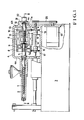
- FIG. 1 is a side view of a part of a molding machine showing in longitudinal section an injection apparatus capable of carrying out the back pressure control method in accordance with the present invention.
- FIG. 2 is a sectional view taken on line II-II of FIG. 1.
- FIG. 3 is a rear view of the injection apparatus with a part thereof cutaway.
- FIG. 4 is a sectional view of the injection apparatus on which is mounted a resin sensor for detecting resin pressure used for detecting back pressure.
- FIG. 5 is a block diagram of a back pressure control circuit.
- The injection apparatus comprises an
injection heating tube 2 containing aninjection plunger 1 having a screw provided in the outer periphery thereof and ahousing 4 on amachine bed 3 which also serves to retain the injection heating tube. Thehousing 4 includes therein a plungermovable member 6 connected to the rear end of theinjection plunger 1 through arotary shaft 5 and supportshafts rear walls rotary shaft 5. The plungermovable member 6 is mounted on thesupport shafts movable member 6 may be slidably moved in a lateral direction. - A small-
diameter extending shaft 5a having agear 8 for rotating the plunger is projectingly provided at the rear end of therotary shaft 5, and the plungermovable member 6 is connected to the end of theshaft 5a through a thrust bearing 9. - A central portion of the plunger
movable member 6 is in the form of a cylindrical shape, and athread receiving member 10 having threads formed in the inner peripheral surface thereof is fitted into the rear end of said central portion, and ascrew shaft 11 is screwed into themember 10 concentric with theinjection plunger 1. - The rear end of the
screw shaft 11 constitutes ashaft portion 11a rotatably retained on a bearingportion 4c of therear wall 4 of the housing by means of a thrust bearing 12, and agear 13 is mounted on theshaft portion 11a. - The
aforesaid gears gears transmission shaft 14 interiorly and on the underside of thehousing 4. Thetransmission shaft 14 and a driving shaft of a DC electrically-operated servo-motor 19 connected to the underside surface of thehousing 4 are connected through adriving belt 20 so that the servo-motor 19 may be used as a driving source to rotate and axially move theinjection plunger 1. -
Reference numeral 21 designates a strain gage for measuring the amount of deformation of therear wall 4b of the housing, which strain gage is mounted on a part which receives a reaction produced when the injection plunger 1 charges the material or it advances, that is, on the bearingportion 4c of therear wall 4b of the housing on which theshaft portion 11a is retained. -
Reference numeral 22 designates a DC electric motor for controlling a backward force (back pressure of the plunger) produced when theinjection plunger 1 charges the material through theshaft portion 11a, whichelectric motor 22 is secured to thebearing portion 4c. - While the back pressure control device in this embodiment is a DC servo-motor, it is to be understood that the device can be an electric motor capable of controlling torque, for example, such as an AC servo-motor, a hysteresis motor, a torque motor, etc.
- The
strain gage 21 is commercially available as a mold type strain gage, in which the strain gage is molded into a plastic casing and fixed to the bearingportion 4c by means of a screw. - Rotation and backward movement (charging of material) of the
injection plunger 1 in the electrically-operated injection apparatus constructed as described above are carried out by rotation of thegears injection plunger 1 is carried out by rotation of thegears - More specifically, in charging the material, the
rotary shaft 5 is rotated by rotation of thegear 8, and theinjection plunger 1 is also rotated so that the material from a hopper is transported to the foremost end of theheating tube 2 by means of the screw. - The backward force generated as the reaction for transporting material in the
injection plunger 1 is transmitted to thethread receiving member 10 through the plungermovable member 6 and further exerted on thescrew shaft 11 to generate in thescrew shaft 11 the rotating force in a direction for moving backward the injection plunger 1 together with themovable member 6. At the same time, theelectric motor 22 is driven and controlled to apply a braking force to thescrew shaft 11 thereby carrying out the charging of material while applying the so-called back pressure (back pressure of plunger) to the molten material. - The thrust is generated as the reaction of the back pressure in the
screw shaft 11. The aforesaid back pressure is carried on therear wall 4b of the housing through the thrust bearing 12, as a consequence of which stress is applied also to therear wall 4b of the housing, and a deformation which is minute corresponding to the back pressure is produced also in the bearingportion 4c mounted on thestrain gage 21, which amount of deformation is electrically measured by thestrain gage 21 and detected as the back pressure. - The aforementioned detection of back pressure is effected by use of the backward force (thrust) of the injection plunger 1 at the time of charging material. On the other hand, an example shown in FIG. 4 shows the case where pressure of molten resin is detected by a
resin pressure sensor 21a mounted on the foremost end of theheating tube 2, and the aforesaid molten resin pressure is used for detection of back pressure. - Next, the method for controlling back pressure will be described with reference to FIG. 5.
- The thus produced back pressure is measured by the
strain gage 21, and when it is amplified by astrain amplifier 23, an electric current I₂ corresponding to the back pressure is produced. - A differential electic current ΔI obtained by adding an electric current I₁ corresponding to back pressure set by a back
pressure setting unit 24 and the back pressure current I₂ fedback to anadder 25 is amplified by anelectric current amplifier 26, after which it is supplied to apower converter 27. Thepower converter 27 is composed of an ignition control circuit which uses a thyristor or a pulse width control circuit which uses a transistor, and is designed so that an amature current corresponding to an amplifying current to be inputted may be directed to the DCelectric motor 22. With this, in the control of back pressure of theinjection plunger 1, the control of driving themotor 22 is carried out by the feedback control so as to assume the set value of back pressure, and the back pressure is controlled with high accuracy. - While in the present embodiment, the servo-motor is provided for the purpose of injection and rotation, and another electric motor is used for exclusive use of back pressure control, it is to be understood that the servo-motor for injection can be used also for back pressure control, and a motor for rotation of the plunger can be separately provided.
- As described above, according to the present invention, the electric motor is used as the control device for back pressure and the electric motor is driven and controlled by the feedback control so that back pressure is in coincidence with the set value to control back pressure. Therefore, the device is not affected by the frictional force of transmission mechanism thus providing for excellent responsiveness and being capable of carrying out back pressure control with high accuracy. In addition, the back pressure control may be performed with high accuracy according to material to be molded or articles to be molded, and the control of back presure can be made with high accuracy. Therefore, the apparatus may be applied as an optimum back pressure controlling method for the injection apparatus using an electric motor as a driving source.
Claims (3)
Priority Applications (2)
| Application Number | Priority Date | Filing Date | Title |
|---|---|---|---|
| DE8686100729T DE3679801D1 (en) | 1986-01-21 | 1986-01-21 | METHOD FOR CONTROLLING THE BACK PRESSURE IN AN ELECTRICALLY OPERABLE INJECTION MOLDING DEVICE. |
| EP19860100729 EP0230488B2 (en) | 1984-07-24 | 1986-01-21 | Method for controlling back pressure in electrically-operated injection apparatus |
Applications Claiming Priority (2)
| Application Number | Priority Date | Filing Date | Title |
|---|---|---|---|
| JP15334084A JPS6131221A (en) | 1984-07-24 | 1984-07-24 | Control of backpressure in injection molding machine |
| EP19860100729 EP0230488B2 (en) | 1984-07-24 | 1986-01-21 | Method for controlling back pressure in electrically-operated injection apparatus |
Publications (4)
| Publication Number | Publication Date |
|---|---|
| EP0230488A2 true EP0230488A2 (en) | 1987-08-05 |
| EP0230488A3 EP0230488A3 (en) | 1988-01-07 |
| EP0230488B1 EP0230488B1 (en) | 1991-06-12 |
| EP0230488B2 EP0230488B2 (en) | 1997-04-09 |
Family
ID=26101622
Family Applications (1)
| Application Number | Title | Priority Date | Filing Date |
|---|---|---|---|
| EP19860100729 Expired - Lifetime EP0230488B2 (en) | 1984-07-24 | 1986-01-21 | Method for controlling back pressure in electrically-operated injection apparatus |
Country Status (1)
| Country | Link |
|---|---|
| EP (1) | EP0230488B2 (en) |
Cited By (10)
| Publication number | Priority date | Publication date | Assignee | Title |
|---|---|---|---|---|
| EP0350872A1 (en) * | 1988-07-13 | 1990-01-17 | Sumitomo Heavy Industries, Ltd | Motor control device for electric injection molding machine |
| GB2331267A (en) * | 1997-11-13 | 1999-05-19 | Toshiba Machine Co Ltd | Injection apparatus for injection molding machine |
| WO2001085429A1 (en) * | 2000-05-08 | 2001-11-15 | Procontrol Ag | Method and device for the injection moulding or pressing of plastic components |
| DE10114006A1 (en) * | 2001-03-22 | 2002-10-10 | Siemens Ag | System measuring injection molding pressure, employs e.g. strain gauge on part affected by drive or injection pressure, which generates corresponding signal |
| US6494701B2 (en) | 2000-05-02 | 2002-12-17 | Engel Maschinenbau Gesellschaft M.B.H. | Injection means for an injection moulding machine |
| EP0968808A3 (en) * | 1998-07-02 | 2003-10-08 | Sumitomo Heavy Industries, Ltd. | Back pressure control for an injection moulding machine |
| DE102007039620A1 (en) | 2006-10-19 | 2008-08-21 | Engel Austria Gmbh | Injection device for injection molding machine, has screw for dosing of plastic, which is supported in pressure plate in rotating manner and pressure plate is displaced longitudinally by two spindles actuated electrically |
| EP2103410A1 (en) * | 2008-03-18 | 2009-09-23 | Sumitomo (SHI) Demag Plastics Machinery GmbH | Plastic injection moulding machine with injection power measuring device |
| EP2239125A1 (en) | 2009-04-07 | 2010-10-13 | Wittmann Battenfeld GmbH | Injection unit of an injection moulding machine |
| EP4059692A3 (en) * | 2021-02-26 | 2023-01-18 | Sumitomo Heavy Industries, Ltd. | Injection molding machine |
Citations (4)
| Publication number | Priority date | Publication date | Assignee | Title |
|---|---|---|---|---|
| EP0090863A1 (en) * | 1981-10-08 | 1983-10-12 | Nissei Plastic Industrial Co., Ltd. | Injection molding apparatus |
| JPS60174625A (en) * | 1984-01-31 | 1985-09-07 | Nissei Plastics Ind Co | Detecting method of injection force in motor-driven injection device |
| JPS6131221A (en) * | 1984-07-24 | 1986-02-13 | Nissei Plastics Ind Co | Control of backpressure in injection molding machine |
| JPS6137409A (en) * | 1984-07-31 | 1986-02-22 | Japan Steel Works Ltd:The | Method of controlling motor driven injection apparatus |
-
1986
- 1986-01-21 EP EP19860100729 patent/EP0230488B2/en not_active Expired - Lifetime
Patent Citations (4)
| Publication number | Priority date | Publication date | Assignee | Title |
|---|---|---|---|---|
| EP0090863A1 (en) * | 1981-10-08 | 1983-10-12 | Nissei Plastic Industrial Co., Ltd. | Injection molding apparatus |
| JPS60174625A (en) * | 1984-01-31 | 1985-09-07 | Nissei Plastics Ind Co | Detecting method of injection force in motor-driven injection device |
| JPS6131221A (en) * | 1984-07-24 | 1986-02-13 | Nissei Plastics Ind Co | Control of backpressure in injection molding machine |
| JPS6137409A (en) * | 1984-07-31 | 1986-02-22 | Japan Steel Works Ltd:The | Method of controlling motor driven injection apparatus |
Cited By (16)
| Publication number | Priority date | Publication date | Assignee | Title |
|---|---|---|---|---|
| EP0350872A1 (en) * | 1988-07-13 | 1990-01-17 | Sumitomo Heavy Industries, Ltd | Motor control device for electric injection molding machine |
| US4950146A (en) * | 1988-07-13 | 1990-08-21 | Sumitomo Heavy Industries, Ltd. | Motor control device for electric injection molding machine |
| GB2331267A (en) * | 1997-11-13 | 1999-05-19 | Toshiba Machine Co Ltd | Injection apparatus for injection molding machine |
| GB2331267B (en) * | 1997-11-13 | 2001-10-17 | Toshiba Machine Co Ltd | Injection apparatus for injection molding machine |
| US6309203B1 (en) | 1997-11-13 | 2001-10-30 | Toshiba Kikai Kabushiki Kaisha | Injection apparatus for injection molding machine |
| EP0968808A3 (en) * | 1998-07-02 | 2003-10-08 | Sumitomo Heavy Industries, Ltd. | Back pressure control for an injection moulding machine |
| US6494701B2 (en) | 2000-05-02 | 2002-12-17 | Engel Maschinenbau Gesellschaft M.B.H. | Injection means for an injection moulding machine |
| WO2001085429A1 (en) * | 2000-05-08 | 2001-11-15 | Procontrol Ag | Method and device for the injection moulding or pressing of plastic components |
| DE10114006C2 (en) * | 2001-03-22 | 2003-07-17 | Siemens Ag | plastic injection molding machine |
| DE10114006A1 (en) * | 2001-03-22 | 2002-10-10 | Siemens Ag | System measuring injection molding pressure, employs e.g. strain gauge on part affected by drive or injection pressure, which generates corresponding signal |
| DE102007039620A1 (en) | 2006-10-19 | 2008-08-21 | Engel Austria Gmbh | Injection device for injection molding machine, has screw for dosing of plastic, which is supported in pressure plate in rotating manner and pressure plate is displaced longitudinally by two spindles actuated electrically |
| DE102007039620B4 (en) * | 2006-10-19 | 2010-08-05 | Engel Austria Gmbh | Injection device for an injection molding machine |
| EP2103410A1 (en) * | 2008-03-18 | 2009-09-23 | Sumitomo (SHI) Demag Plastics Machinery GmbH | Plastic injection moulding machine with injection power measuring device |
| US7950915B2 (en) | 2008-03-18 | 2011-05-31 | Sumitomo (Shi) Demag Plastics Machinery Gmbh | Plastics injection molding machine with injection force measuring device |
| EP2239125A1 (en) | 2009-04-07 | 2010-10-13 | Wittmann Battenfeld GmbH | Injection unit of an injection moulding machine |
| EP4059692A3 (en) * | 2021-02-26 | 2023-01-18 | Sumitomo Heavy Industries, Ltd. | Injection molding machine |
Also Published As
| Publication number | Publication date |
|---|---|
| EP0230488A3 (en) | 1988-01-07 |
| EP0230488B2 (en) | 1997-04-09 |
| EP0230488B1 (en) | 1991-06-12 |
Similar Documents
| Publication | Publication Date | Title |
|---|---|---|
| US4758391A (en) | Method for controlling back pressure in electrically-operated injection apparatus | |
| EP0230488A2 (en) | Method for controlling back pressure in electrically-operated injection apparatus | |
| JPH0448339B2 (en) | ||
| WO2001058661A1 (en) | Injection molding machine and method of controlling the injection molding machine | |
| US4879077A (en) | Control method of injection molding machine | |
| KR0136385B1 (en) | Motor control device for electric injection molding machine | |
| US4851171A (en) | Method and apparatus for controlling back pressure in injection molding machine | |
| JPS60174625A (en) | Detecting method of injection force in motor-driven injection device | |
| JPH0440176B2 (en) | ||
| EP0285664A1 (en) | Apparatus for detecting metal mold touch position in an electrically powered straight-acting mold-clamping mechanism | |
| CA1257756A (en) | Method for controlling back pressure in electrically-operated injection apparatus | |
| EP1207032A1 (en) | Method for controlling injection molding machine capable of reducing variations in weight of molded product | |
| KR930003743B1 (en) | Method for controlling back pressure in electrically operated injection apparatus | |
| JPS61217227A (en) | Back pressure control for injection molding machine | |
| JPH035293B2 (en) | ||
| JPS62264924A (en) | Control equipment of measured back pressure of motor driven injection molding machine | |
| JP3534990B2 (en) | Control method of injection molding machine | |
| JP2002079555A (en) | Injection device of injection molding machine and method for controlling injection device | |
| JPS61222718A (en) | Injection control of electrically operated injection unit | |
| JP2762221B2 (en) | Plasticization control method for electric injection molding machine | |
| JPH0344889B2 (en) | ||
| JP3535063B2 (en) | Injection molding machine | |
| JPH0144491B2 (en) | ||
| JP2834444B2 (en) | Electric injection molding machine | |
| JPH0476768B2 (en) |
Legal Events
| Date | Code | Title | Description |
|---|---|---|---|
| PUAI | Public reference made under article 153(3) epc to a published international application that has entered the european phase |
Free format text: ORIGINAL CODE: 0009012 |
|
| AK | Designated contracting states |
Kind code of ref document: A2 Designated state(s): DE FR GB |
|
| PUAL | Search report despatched |
Free format text: ORIGINAL CODE: 0009013 |
|
| AK | Designated contracting states |
Kind code of ref document: A3 Designated state(s): DE FR GB |
|
| 17P | Request for examination filed |
Effective date: 19880526 |
|
| 17Q | First examination report despatched |
Effective date: 19890428 |
|
| GRAA | (expected) grant |
Free format text: ORIGINAL CODE: 0009210 |
|
| AK | Designated contracting states |
Kind code of ref document: B1 Designated state(s): DE FR GB |
|
| REF | Corresponds to: |
Ref document number: 3679801 Country of ref document: DE Date of ref document: 19910718 |
|
| ET | Fr: translation filed | ||
| PLBI | Opposition filed |
Free format text: ORIGINAL CODE: 0009260 |
|
| 26 | Opposition filed |
Opponent name: BATTENFELD GMBH Effective date: 19920312 |
|
| APAC | Appeal dossier modified |
Free format text: ORIGINAL CODE: EPIDOS NOAPO |
|
| PLAW | Interlocutory decision in opposition |
Free format text: ORIGINAL CODE: EPIDOS IDOP |
|
| PUAH | Patent maintained in amended form |
Free format text: ORIGINAL CODE: 0009272 |
|
| STAA | Information on the status of an ep patent application or granted ep patent |
Free format text: STATUS: PATENT MAINTAINED AS AMENDED |
|
| 27A | Patent maintained in amended form |
Effective date: 19970409 |
|
| AK | Designated contracting states |
Kind code of ref document: B2 Designated state(s): DE FR GB |
|
| ET3 | Fr: translation filed ** decision concerning opposition | ||
| REG | Reference to a national code |
Ref country code: GB Ref legal event code: IF02 |
|
| PGFP | Annual fee paid to national office [announced via postgrant information from national office to epo] |
Ref country code: DE Payment date: 20041206 Year of fee payment: 20 |
|
| PGFP | Annual fee paid to national office [announced via postgrant information from national office to epo] |
Ref country code: GB Payment date: 20050112 Year of fee payment: 20 |
|
| PGFP | Annual fee paid to national office [announced via postgrant information from national office to epo] |
Ref country code: FR Payment date: 20050119 Year of fee payment: 20 |
|
| APAH | Appeal reference modified |
Free format text: ORIGINAL CODE: EPIDOSCREFNO |
|
| PG25 | Lapsed in a contracting state [announced via postgrant information from national office to epo] |
Ref country code: GB Free format text: LAPSE BECAUSE OF EXPIRATION OF PROTECTION Effective date: 20060120 |
|
| REG | Reference to a national code |
Ref country code: GB Ref legal event code: PE20 |