EP0230403B1 - Elevating device for the mast sections of a sectional mast, especially a movable aerial mast of framework type - Google Patents
Elevating device for the mast sections of a sectional mast, especially a movable aerial mast of framework type Download PDFInfo
- Publication number
- EP0230403B1 EP0230403B1 EP19870850011 EP87850011A EP0230403B1 EP 0230403 B1 EP0230403 B1 EP 0230403B1 EP 19870850011 EP19870850011 EP 19870850011 EP 87850011 A EP87850011 A EP 87850011A EP 0230403 B1 EP0230403 B1 EP 0230403B1
- Authority
- EP
- European Patent Office
- Prior art keywords
- mast
- jacket
- sections
- transport screw
- screw
- Prior art date
- Legal status (The legal status is an assumption and is not a legal conclusion. Google has not performed a legal analysis and makes no representation as to the accuracy of the status listed.)
- Expired
Links
- 230000003028 elevating effect Effects 0.000 title claims description 9
- 230000007246 mechanism Effects 0.000 claims description 11
- 230000002093 peripheral effect Effects 0.000 claims description 4
- 238000010168 coupling process Methods 0.000 description 4
- 238000005859 coupling reaction Methods 0.000 description 4
- 230000008878 coupling Effects 0.000 description 2
- 229910000906 Bronze Inorganic materials 0.000 description 1
- 239000010974 bronze Substances 0.000 description 1
- 230000008094 contradictory effect Effects 0.000 description 1
- KUNSUQLRTQLHQQ-UHFFFAOYSA-N copper tin Chemical compound [Cu].[Sn] KUNSUQLRTQLHQQ-UHFFFAOYSA-N 0.000 description 1
- 238000003780 insertion Methods 0.000 description 1
- 230000037431 insertion Effects 0.000 description 1
- 239000000463 material Substances 0.000 description 1
- 230000000087 stabilizing effect Effects 0.000 description 1
Images

Classifications
-
- E—FIXED CONSTRUCTIONS
- E04—BUILDING
- E04H—BUILDINGS OR LIKE STRUCTURES FOR PARTICULAR PURPOSES; SWIMMING OR SPLASH BATHS OR POOLS; MASTS; FENCING; TENTS OR CANOPIES, IN GENERAL
- E04H12/00—Towers; Masts or poles; Chimney stacks; Water-towers; Methods of erecting such structures
- E04H12/34—Arrangements for erecting or lowering towers, masts, poles, chimney stacks, or the like
Definitions
- the present invention refers to and elevating device for lifting the mast by the lowermost mast sections a sectional mast, especially a movable aerial mast of framework type, comprising a foot portion with a mast support and guide jacket, said elevating device including a power-operated screw mechanism, the elongated transport screw of which extends vertically along one side of the guide jocket.
- Such a mast and lifting device is known from BE-A 449 601.
- Movable aerial masts have to fill a plurality of partly contradictory requirements. Thus, they have to be strong and rigid but still relatively light and easily mountable and dismountable.
- Conventional mast structures usually are of framework type and the masts are put together from a number of sections. The mast is erected by arranging at a desired place a foot portion of the mast having a support and guide jacket therefor and introducing into said jacket the sections one by one, coupling them together with the nearest preceding section and raising them by means of any suitable raising and lowering mechanism a sufficient distance for allowing the introduction of the subsequent mast section into the jacket.
- the conventional raising and lowering mechanisms have been rope blocks or chain winches having a hook which is connected with the lower end of each mast section after the same has been inserted into the guide jacket after which raising is made, the mast is locked, the hook released and the raising and lowering mechanism returned to the initial position for again connecting the hook to the lower end of the subsequent mast section.
- the object of the present invention now is to suggest such a device and the invention comprises mast and device of the aforementioned type which is characterized in that the screw contacts externally with its periphery the peripheral contour of a mast section housed parallel therewith within the jacket and in that each mast section in its lower portion at the point of contact on the peripheral contour is provided with a mechanical component serving as an open-sided nut segment meshing with the threads of the transport screw.
- the transport screw certainly operates intermittently but permanently in the same direction during the erection of the mast and in the opposite direction during the lowering of said mast.
- the respective mast sections only need to be inserted into the support and guide jacket of the foot portion in order to be brought directly into meshing with the transport screw with its nut segment, after which the screw is rotated and the mast section together with the preceding sections is raised a distance substantially corresponding to the length of one section, after which the subsequent mast section is introduced into the guide jacket, coupled to the preceding mast section and thereafter raised by means of the transport screw in cooperation with the nut segment of the last-mentioned section.
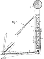
- Fig 1 is a side elevational view of a mast with an elevating device according to the invention with a support and guide jacket in a foot portion of the mast and Fig 2 is a plan view from above of said guide jacket.
- a movable aerial mast of framework type comprises a foot portion 1 and a plurality of mutually equal mast sections 2 of framework type and in the present case having triangular cross section.
- the uppermost section carries in its upper end an aerial element such as a pa- raboloidal aerial 3.
- the sections 2 are provided with suitable mountings for some suitable kind of coupling means such as a bolt connection of easy-coupling type.
- the mast In its erected position the mast rests with its lowermost sections in a support and guide jacket 4 having an elevating device 5.
- the jacket has the same general cross sectional shape as the mast sections 2, in the present case thus triangular shape, and surrounds the lowermost mast sections 2 with moderate clearance.
- the height of the jacket substantially corresponds to the total length of two mast sections 2 and for stabilizing the mast the jacket 4 is provided with support legs 6 and side struts 7 protruding from the corners of the triangular cross section. From the top as well as from other levels of height of the mast, if desired, usually also extend span wires 8.
- the jacket which suitably also is of framework type, is provided in the lower portion of one of its sides with an opening 10 in said side wall.
- the mast sections 2 are guided by means of suitable guide members 11, preferably in the form of guide rollers cooperating with the corner edges of said mast sections 2.
- the elevating or raising and lowering mechanism 5 may comprise an elongated vertical transport screw 12 which is along another side of the guide jacket 4 also provided with a suitable opening.
- the screw 12 has a length which at least corresponds to the length of each mast section 2 and extends from a bottom of the guide jacket 4 and upwardly to a position above the level of a mast section 2 standing on the bottom of the jacket 4 or, in other words above the open portion of the framework at the insertion and removal side of the jacket 4.
- the transport screw 12 is connected with some suitable kind of drive mechanism 13 not further illustrated, such as a worm drive driven by an electric motor for 12 or 24 volts.
- the device also is provided with a connection for mounting of a hand crank for allowing manual operation of the transport screw in case of lack of electric current.
- the transport screw 12 may be arranged in a plane coinciding with the center line of the adjacent jacket side such that the screw with its periphery approximately contacts externally one of the sides of a mast section 2 located in the jacket 4 and oriented parallelly thereto along an axis extending in said side, said axis preferably being the longitudinal center line of said side.
- each mast section 2 according to the invention may be provided at the lower end of said center line with a nut segment 14 adapted for meshing with the threads of said transport screw 12.
- the nut segment may be constituted by a slide block of suitable material such as bronze or by a roller.
- the mast provided with the elevating device according to the invention may be erected in the following way. Firstly, the support and guide jacket 4 is arranged and levelled at the desired place and thereafter a first mast section 2 is inserted into the guide jacket 4 through the opening in one of the sides thereof, said section 2 of course being oriented in such a way that a side provided with a nut segment 14 is turned towards the side of the jacket 4 at which transport screw 12 is located. After that the rotation of the transport screw 12 is started and owing to the movement of the nut segment 14 along the threads of the screw 12 a raising of the mast section 2 through the jacket 4 is obtained.
Landscapes
- Engineering & Computer Science (AREA)
- Architecture (AREA)
- Civil Engineering (AREA)
- Structural Engineering (AREA)
- Forklifts And Lifting Vehicles (AREA)
Description
- The present invention refers to and elevating device for lifting the mast by the lowermost mast sections a sectional mast, especially a movable aerial mast of framework type, comprising a foot portion with a mast support and guide jacket, said elevating device including a power-operated screw mechanism, the elongated transport screw of which extends vertically along one side of the guide jocket.
- Such a mast and lifting device is known from BE-A 449 601.
- Movable aerial masts have to fill a plurality of partly contradictory requirements. Thus, they have to be strong and rigid but still relatively light and easily mountable and dismountable. Conventional mast structures usually are of framework type and the masts are put together from a number of sections. The mast is erected by arranging at a desired place a foot portion of the mast having a support and guide jacket therefor and introducing into said jacket the sections one by one, coupling them together with the nearest preceding section and raising them by means of any suitable raising and lowering mechanism a sufficient distance for allowing the introduction of the subsequent mast section into the jacket. For this purpose the conventional raising and lowering mechanisms have been rope blocks or chain winches having a hook which is connected with the lower end of each mast section after the same has been inserted into the guide jacket after which raising is made, the mast is locked, the hook released and the raising and lowering mechanism returned to the initial position for again connecting the hook to the lower end of the subsequent mast section. When lowering the mast and dismounting thereof, the operation of course is carried out in the same way although in reversed order.
- In another kind of mast design which has mutually telescopically movable sections it has also been suggested to utilize a centrally mounted transport screw for expansion and retraction of the mast.
- Conventional framework masts of the kind referred to above and put together in sections have turned out to serve their purpose rather well but at many occasions of use in which the time aspect is essential the conventional raising and lowering mechanism has been considered to operate too slow since it has to be returned to the initial position after each working movement. There is thus a need for a faster operating device for this purpose.
- Quite surprisingly it has now turned out that this can be achieved very easily by means of a differently designed screw mechanism which does not require any return movement between the working movements. The object of the present invention now is to suggest such a device and the invention comprises mast and device of the aforementioned type which is characterized in that the screw contacts externally with its periphery the peripheral contour of a mast section housed parallel therewith within the jacket and in that each mast section in its lower portion at the point of contact on the peripheral contour is provided with a mechanical component serving as an open-sided nut segment meshing with the threads of the transport screw.
- Owing to said design, the transport screw certainly operates intermittently but permanently in the same direction during the erection of the mast and in the opposite direction during the lowering of said mast. The respective mast sections only need to be inserted into the support and guide jacket of the foot portion in order to be brought directly into meshing with the transport screw with its nut segment, after which the screw is rotated and the mast section together with the preceding sections is raised a distance substantially corresponding to the length of one section, after which the subsequent mast section is introduced into the guide jacket, coupled to the preceding mast section and thereafter raised by means of the transport screw in cooperation with the nut segment of the last-mentioned section.
- By way of example, the invention is further described below with reference to the accompanying drawing, in which Fig 1 is a side elevational view of a mast with an elevating device according to the invention with a support and guide jacket in a foot portion of the mast and Fig 2 is a plan view from above of said guide jacket.
- As is evident from the drawing a movable aerial mast of framework type comprises a foot portion 1 and a plurality of mutually
equal mast sections 2 of framework type and in the present case having triangular cross section. The uppermost section carries in its upper end an aerial element such as a pa- raboloidal aerial 3. At each end thesections 2 are provided with suitable mountings for some suitable kind of coupling means such as a bolt connection of easy-coupling type. In its erected position the mast rests with its lowermost sections in a support and guide jacket 4 having anelevating device 5. The jacket has the same general cross sectional shape as themast sections 2, in the present case thus triangular shape, and surrounds thelowermost mast sections 2 with moderate clearance. The height of the jacket substantially corresponds to the total length of twomast sections 2 and for stabilizing the mast the jacket 4 is provided withsupport legs 6 and side struts 7 protruding from the corners of the triangular cross section. From the top as well as from other levels of height of the mast, if desired, usually also extend span wires 8. - In order to provide for the
individual mast sections 2 one by one into the support and guide jacket 4 when erecting the mast as well as for removal of said sections in the corresponding manner when dismounting the mast, the jacket which suitably also is of framework type, is provided in the lower portion of one of its sides with an opening 10 in said side wall. Within the guide jacket themast sections 2 are guided by means ofsuitable guide members 11, preferably in the form of guide rollers cooperating with the corner edges of saidmast sections 2. - According to the invention the elevating or raising and lowering
mechanism 5 may comprise an elongatedvertical transport screw 12 which is along another side of the guide jacket 4 also provided with a suitable opening. Thescrew 12 has a length which at least corresponds to the length of eachmast section 2 and extends from a bottom of the guide jacket 4 and upwardly to a position above the level of amast section 2 standing on the bottom of the jacket 4 or, in other words above the open portion of the framework at the insertion and removal side of the jacket 4. At said position thetransport screw 12 is connected with some suitable kind ofdrive mechanism 13 not further illustrated, such as a worm drive driven by an electric motor for 12 or 24 volts. Suitably the device also is provided with a connection for mounting of a hand crank for allowing manual operation of the transport screw in case of lack of electric current. - According to the invention the
transport screw 12 may be arranged in a plane coinciding with the center line of the adjacent jacket side such that the screw with its periphery approximately contacts externally one of the sides of amast section 2 located in the jacket 4 and oriented parallelly thereto along an axis extending in said side, said axis preferably being the longitudinal center line of said side. At least at one of its sides eachmast section 2 according to the invention may be provided at the lower end of said center line with anut segment 14 adapted for meshing with the threads of saidtransport screw 12. The nut segment may be constituted by a slide block of suitable material such as bronze or by a roller. - The mast provided with the elevating device according to the invention may be erected in the following way. Firstly, the support and guide jacket 4 is arranged and levelled at the desired place and thereafter a
first mast section 2 is inserted into the guide jacket 4 through the opening in one of the sides thereof, saidsection 2 of course being oriented in such a way that a side provided with anut segment 14 is turned towards the side of the jacket 4 at whichtransport screw 12 is located. After that the rotation of thetransport screw 12 is started and owing to the movement of thenut segment 14 along the threads of the screw 12 a raising of themast section 2 through the jacket 4 is obtained. When themast section 2 has been raised to such an extent that asubsequent mast section 2 can be inserted into the guide jacket 4, the rotation of thetransport screw 12 is stopped. This can easily be provided by a limit switch for the electric drive motor or any similar manner obvious to the artisan. Thesubsequent mast section 2 which has been inserted into the jacket 4 is coupled with its upper end to the lower end of the precedingmast section 2 by means of a bolt connection of easy-coupling type not further illustrated, after which the rotation of thetransport screw 12 again is started, now in the same direction as during the first transport movement and without any need of a return movement such as in rope blocks or other raising and lowering mechanisms previously used for the same purpose. This is repeated until all, in the present case 19, mast sections have been brought into position and been coupled to each other. - When dismounting the mast the same operation is repeated although in reversed order. For locking at each occasion the
respective mast section 2 next to the lowermost one in the guide jacket 4 it is suitable that thetransport screw 12 or thescrew 12 together with thedrive mechanism 13 is of a self-braking type. Said locking also can be provided by locking means, not illustrated.
Claims (2)
Applications Claiming Priority (2)
| Application Number | Priority Date | Filing Date | Title |
|---|---|---|---|
| SE8600213A SE451376B (en) | 1986-01-17 | 1986-01-17 | HIGH AND SINGLE DEVICE FOR MASTER SECTIONS AT A SECTIONAL COMPOSITIVE MAST, SPECIFICALLY A REMOVABLE ANTENNMAST OF TRAINING TYPE |
| SE8600213 | 1986-01-17 |
Publications (2)
| Publication Number | Publication Date |
|---|---|
| EP0230403A1 EP0230403A1 (en) | 1987-07-29 |
| EP0230403B1 true EP0230403B1 (en) | 1989-08-09 |
Family
ID=20363133
Family Applications (1)
| Application Number | Title | Priority Date | Filing Date |
|---|---|---|---|
| EP19870850011 Expired EP0230403B1 (en) | 1986-01-17 | 1987-01-16 | Elevating device for the mast sections of a sectional mast, especially a movable aerial mast of framework type |
Country Status (3)
| Country | Link |
|---|---|
| EP (1) | EP0230403B1 (en) |
| DE (1) | DE3760412D1 (en) |
| SE (1) | SE451376B (en) |
Family Cites Families (10)
| Publication number | Priority date | Publication date | Assignee | Title |
|---|---|---|---|---|
| BE449601A (en) * | ||||
| DE1066720B (en) * | 1959-10-08 | |||
| DE119095C (en) * | ||||
| FR1256677A (en) * | 1960-02-12 | 1961-03-24 | Device for mounting mast cranes formed from superimposed elements | |
| DE1228040B (en) * | 1961-09-19 | 1966-11-03 | Markus Schmidt Tychsen Derrick | Crane whose column is built up from a plurality of mast elements |
| FR1325120A (en) * | 1962-03-23 | 1963-04-26 | Extendable Support Mast Installation | |
| AT292966B (en) * | 1966-10-12 | 1971-09-27 | Friedrich Freimueller | Lattice mast built from shots |
| FR1543012A (en) * | 1967-10-24 | 1968-10-18 | Device for transforming a rotary movement into a rectilinear translation, particularly for moving a load | |
| FR1585396A (en) * | 1968-11-26 | 1970-01-16 | ||
| FR2247913A6 (en) * | 1971-07-22 | 1975-05-09 | Comabi | Elevator formed of scaffolding frames - has ladder elements enclosing vert. operating screws |
-
1986
- 1986-01-17 SE SE8600213A patent/SE451376B/en not_active IP Right Cessation
-
1987
- 1987-01-16 DE DE8787850011T patent/DE3760412D1/en not_active Expired
- 1987-01-16 EP EP19870850011 patent/EP0230403B1/en not_active Expired
Also Published As
| Publication number | Publication date |
|---|---|
| SE451376B (en) | 1987-10-05 |
| SE8600213L (en) | 1987-07-18 |
| EP0230403A1 (en) | 1987-07-29 |
| DE3760412D1 (en) | 1989-09-14 |
| SE8600213D0 (en) | 1986-01-17 |
Similar Documents
| Publication | Publication Date | Title |
|---|---|---|
| US4497591A (en) | Advancing mechanism and system utilizing same for raising and lowering a work platform | |
| US3679174A (en) | Jack or lift mechanism and drive therefor | |
| KR20180035717A (en) | Apparatus for lifting heavy loads | |
| CN109650226A (en) | A kind of hydraulic lifting steel platform fall arrest supporting beam column system and its application method | |
| US4655640A (en) | Advancing mechanism and system utilizing same for raising and lowering a work platform | |
| US4125193A (en) | Climbing device for climbing crane | |
| EP0026543B1 (en) | Self-erecting telescopable structure | |
| EP0230403A1 (en) | Elevating device for the mast sections of a sectional mast, especially a movable aerial mast of framework type | |
| US5131628A (en) | Mechanical jack | |
| US5715906A (en) | Moving work floor push-up expansion floor device | |
| CN107246138A (en) | A building construction elevating platform with recyclable material feeding | |
| JPH08100517A (en) | Elevating workbench | |
| US3493129A (en) | Vehicle garage | |
| KR960002897Y1 (en) | Lift for vehicles | |
| CN214996606U (en) | Warning fence device | |
| CN115259029B (en) | Novel construction site lifting device | |
| CN112850565A (en) | Stone tablet installation lifting mechanism for building | |
| CN121346129A (en) | A single-drive, long-stroke lifting device for outdoor LED screens | |
| KR102761807B1 (en) | Device for assembling and disassembling mast of tower crane | |
| CN116290920B (en) | Foldable ramp capable of being spliced | |
| RU2793508C2 (en) | Lifting mechanism for rail lifting system | |
| SU853058A1 (en) | Powered sliding prop | |
| KR100197299B1 (en) | Parking system | |
| KR940005910Y1 (en) | Parking lot | |
| EP1153878A2 (en) | Control device for a lifting platform |
Legal Events
| Date | Code | Title | Description |
|---|---|---|---|
| PUAI | Public reference made under article 153(3) epc to a published international application that has entered the european phase |
Free format text: ORIGINAL CODE: 0009012 |
|
| AK | Designated contracting states |
Kind code of ref document: A1 Designated state(s): CH DE FR GB IT LI |
|
| 17P | Request for examination filed |
Effective date: 19871212 |
|
| 17Q | First examination report despatched |
Effective date: 19881111 |
|
| GRAA | (expected) grant |
Free format text: ORIGINAL CODE: 0009210 |
|
| AK | Designated contracting states |
Kind code of ref document: B1 Designated state(s): CH DE FR GB IT LI |
|
| ITF | It: translation for a ep patent filed | ||
| ET | Fr: translation filed | ||
| REF | Corresponds to: |
Ref document number: 3760412 Country of ref document: DE Date of ref document: 19890914 |
|
| PLBE | No opposition filed within time limit |
Free format text: ORIGINAL CODE: 0009261 |
|
| STAA | Information on the status of an ep patent application or granted ep patent |
Free format text: STATUS: NO OPPOSITION FILED WITHIN TIME LIMIT |
|
| 26N | No opposition filed | ||
| PGFP | Annual fee paid to national office [announced via postgrant information from national office to epo] |
Ref country code: GB Payment date: 19920114 Year of fee payment: 6 Ref country code: FR Payment date: 19920114 Year of fee payment: 6 |
|
| PGFP | Annual fee paid to national office [announced via postgrant information from national office to epo] |
Ref country code: DE Payment date: 19920127 Year of fee payment: 6 |
|
| PGFP | Annual fee paid to national office [announced via postgrant information from national office to epo] |
Ref country code: CH Payment date: 19920128 Year of fee payment: 6 |
|
| ITTA | It: last paid annual fee | ||
| PG25 | Lapsed in a contracting state [announced via postgrant information from national office to epo] |
Ref country code: GB Effective date: 19930116 |
|
| PG25 | Lapsed in a contracting state [announced via postgrant information from national office to epo] |
Ref country code: LI Effective date: 19930131 Ref country code: CH Effective date: 19930131 |
|
| GBPC | Gb: european patent ceased through non-payment of renewal fee |
Effective date: 19930116 |
|
| PG25 | Lapsed in a contracting state [announced via postgrant information from national office to epo] |
Ref country code: FR Effective date: 19930930 |
|
| REG | Reference to a national code |
Ref country code: CH Ref legal event code: PL |
|
| PG25 | Lapsed in a contracting state [announced via postgrant information from national office to epo] |
Ref country code: DE Effective date: 19931001 |
|
| REG | Reference to a national code |
Ref country code: FR Ref legal event code: ST |
|
| PG25 | Lapsed in a contracting state [announced via postgrant information from national office to epo] |
Ref country code: IT Free format text: LAPSE BECAUSE OF NON-PAYMENT OF DUE FEES;WARNING: LAPSES OF ITALIAN PATENTS WITH EFFECTIVE DATE BEFORE 2007 MAY HAVE OCCURRED AT ANY TIME BEFORE 2007. THE CORRECT EFFECTIVE DATE MAY BE DIFFERENT FROM THE ONE RECORDED. Effective date: 20050116 |