EP0230372A2 - Vibratory seismic source for generating combined compressional and shear waves - Google Patents
Vibratory seismic source for generating combined compressional and shear waves Download PDFInfo
- Publication number
- EP0230372A2 EP0230372A2 EP87300277A EP87300277A EP0230372A2 EP 0230372 A2 EP0230372 A2 EP 0230372A2 EP 87300277 A EP87300277 A EP 87300277A EP 87300277 A EP87300277 A EP 87300277A EP 0230372 A2 EP0230372 A2 EP 0230372A2
- Authority
- EP
- European Patent Office
- Prior art keywords
- base plate
- turntable
- vibratory
- earth
- vibration means
- Prior art date
- Legal status (The legal status is an assumption and is not a legal conclusion. Google has not performed a legal analysis and makes no representation as to the accuracy of the status listed.)
- Granted
Links
Images

Classifications
-
- G—PHYSICS
- G01—MEASURING; TESTING
- G01V—GEOPHYSICS; GRAVITATIONAL MEASUREMENTS; DETECTING MASSES OR OBJECTS; TAGS
- G01V1/00—Seismology; Seismic or acoustic prospecting or detecting
- G01V1/02—Generating seismic energy
- G01V1/04—Details
- G01V1/047—Arrangements for coupling the generator to the ground
- G01V1/053—Arrangements for coupling the generator to the ground for generating transverse waves
-
- Y—GENERAL TAGGING OF NEW TECHNOLOGICAL DEVELOPMENTS; GENERAL TAGGING OF CROSS-SECTIONAL TECHNOLOGIES SPANNING OVER SEVERAL SECTIONS OF THE IPC; TECHNICAL SUBJECTS COVERED BY FORMER USPC CROSS-REFERENCE ART COLLECTIONS [XRACs] AND DIGESTS
- Y10—TECHNICAL SUBJECTS COVERED BY FORMER USPC
- Y10S—TECHNICAL SUBJECTS COVERED BY FORMER USPC CROSS-REFERENCE ART COLLECTIONS [XRACs] AND DIGESTS
- Y10S181/00—Acoustics
- Y10S181/40—Wave coupling
- Y10S181/401—Earth
Definitions
- This invention relates generally to the field of seismic exploration and more particularly to an improved apparatus for imparting vibrational energy to the earth wherein selected combinations of compressional and shear wave energy can be generated simultaneously.
- a method and apparatus which provides simultaneous 1 compressional and shear waves of both SH and SV type utilizing but a single vibrating mass is taught in commonly assigned U.S. Patent Application Serial No. 792,531 filed October 29, 1985 in the name of Tom Airhart and entitled "Full Wave Field Vibratory Seismic Source".
- the apparatus described in the subject patent application couples a vibrating mass to a ground engaging base plate so as to enable pivotal rotation of the vibrating mass about two mutually perpendicular rotational axes. In this way the vibratory axis of the vibrating mass may be made to coincide with any preselected vector path. This vector path can then be oriented with respect to a remotely located three element orthogonal geophone so as to enable simultaneous generation and detection of compressional and shear SH and SV waves.
- the relative amplitudes of such waves are varied by selecting any desired combination of tilt and azimuth for the vibratory axis.
- the vibrating mass is linked to the base plate through two separately rotatable shafts.
- the mechanical linkage through such shafts must be substantially free of misalignment and built to close tolerances.
- the present invention proposes apparatus for imparting vibraticnal energy to the earth utilizing a single vibrating means which is coupled to an earth engaging base plate for operation along any desired vector path without altering the position of such base plate. Coupling is accomplished directly between the vibrating means and the base plate without the intervention of any separately moveable intermediate member or element.
- the vibratory means comprises a double rod end piston which reciprocates relative to the motion of a reaction mass slidably mounted on such piston.
- a ball fixed to the lower rod end is housed within a socket embedded in or otherwise fixed to the surface of the base p1ate. The ball is free to turn in any direction within the socket when the vibratory axis of the vibrating means is varied. However, the ball remains captured within the socket so that the base plate must follow both upward and downward movement of the vibrating means.
- the invention comprises any suitable means for supporting and applying a force or forces against the upper rod end in order to vary the tilt and azimuth of the vibrating axis so that its direction coincides with the desired vector path.
- the upper rod end may extend through a radial slot in a rotatable turntable horizontally mounted above the base plate such as on a transport vehicle.
- Means such as a hydraulic cylinder are adjustably secured between the turntable and the upper rod end for urging such end radially along the slot. This causes the vibrating means to pivot on its lower ball end in a vertical plane.
- Cylindrical vibrator assembly 10 may be of the type utilizing a reaction mass mounted for reciprocal motion on a double rod end piston under hydraulic control, all as well known to the art.
- reaction mass 11 is slidably mounted on a double rod end piston (not shown) having outwardly projecting rod ends 13 and 14.
- Mass 11 is hydraulically reciprocated through a short stroke at varying frequencies. As the mass 11 moves the corresponding opposite movements of the piston are coupled to base plate 12 thus transferring seismic vibrations into the earth.
- the manner of attachment of the vibrating means 10 to the base plate 12 and the means for adjustment of the vibratory axis of the vibrating means 10 will be more particularly described below.
- a ball fixed to lower rod end 13 is recessed within socket 16 which is embedded in or otherwise secured to the surface of base plate 12.
- Ball 15 is rotatable in any direction about its center and therefore constitutes a "universal" pivot for vibration assembly 10.
- adjustment of the vector path of vibrator assembly 10 is preferably accomplished with the aid of turntable 17 mounted horizontally on raised bed 18 carried upon frame 19 of any suitable transport vehicle (not shown).
- Turntable 17 is provided with a radial slot 21 through which the upper rod end 14 of assembly 10 extends in slidable relation.
- Hydraulic cylinder 24 is mounted on turntable 17 by means of a bracket 25 so that its piston rod 2ii is aligned with slot 21, the external end of rod 26 being pivotally interconnected with a cylindrical sleeve 25 surrounding upper rod end 14. Movement of piston rod 26 slides upper rod end 14 along slot 21, thereby causing vibrational axis 29 of assembly 10 to pivot about ball 15 so that axis 29 assumes any desired angle ⁇ with respect to a vertical position.
- Rotation of turntable 17 is provided through drive gear 30 and chain drive 31 operated by reversible motor 32 situated beneath bed 18. Suitable means are provided such as a dependent flange (not shown) for rotatably anchoring turntable 17 to bed 18. As best seen with reference to FIG. 3 turntable slot 21 can in this manner be rotated through any desired angle ⁇ 1 so that slot 21 assumes any desired azimuthal position. This in turn causes a corresponding rotation of the vibrational axis 29 of assembly 10 accompanied by corresponding pivotal movement about ball 15.
- socket 16 is provided with an upwardly opening inverted cone- shaped aperture 33 which subtends a solid angle sufficient to accommodate any desired pivotal movement of vibrational axis 29 of vibrator assembly 10.
- the circumference of ball 15 is larger than the diameter of aperture 33 at its lower end.
- ball 15 is securely captured within socket 16 and faithfully transmits to base p'late 12 the vibratory motion of assembly 10 in both up and down directions.
- An advantage of this design is that vibrator assembly 10 may be tilted in any direction from the vertical directly to a desired vector path or alternatively this path may be arrived at by rotation about two different axes.
- ball 15 and socket 16 are compatible with a variety of means for application of the necessary forces to effect adjustment of the vibrational axis 29. Regardless of the means selected for such adjustment, since no intermediate movable element separates vibrator assembly 10 and base plate 12, any possible mechanical misalignment resulting from the use of such element is avoided. This lessens or eliminates one source of possible attenuation or distortion of the seismic signal to be generated.
- ball 15 may be either a complete sphere or of other shape provided the surface thereof interfacing with socket 16 is itself substantially spherical. Suitable bearing means whether liquid or solid may be applied between such interfacing surfaces to insure ease of adjustment of the position of assembly 10.
- base plate 12 is interconnected with vehicle frame 19 by means of adjustable hydraulic support members 40.
- adjustable hydraulic support members 40 By extending support members 40 one can shift the weight of the transport vehicle entirely or in part from its spring suspension and its tires so as to bear directly upon and stabilize base plate 12.
- a seismic line As an illustration, as shown in FIG. 5 one can align the transport vehicle so that it extends along a perpendicular 46 to seismic line 47 terminating in remote three-element orthogonal geophone 48. In this way rotation of slot 21 through any angle can establish the desired angular relation to line 47.
- vibratory axis 29 of assembly 10 lies at angle ⁇ to the vertical direction 49 so that the vector path of assembly 10 falls within vertical plane 50.
- the angle ⁇ is limited to near vertical, i.e.; 5 degrees to not more than 25 degrees from vertical, the amplitude of the resultant shear wave energy for some near surface ground conditions is believed to retain the maximun value which can be achieved with a device of the character of assembly 10.
- the increased compression of the ground resulting from such near vertical stress increases shear stiffness and strength in the ground where those properties are deficient.
- the underside of base plate 12 may be provided with inverted pyramidal cleats (not shown).
- Such coupling devices are well known as described, for example, in United States Patent No. 3, 1 .59,232 issued to D. W. Fair on December 1, 1964.
- Frequency and sweep wave control of the apparatus of this invention may be accomplished in a manner well known to those skilled in this art utilizing hydraulic supply 60 and control valves 62.
- Servo valves 64 may then be operated by signals from sweep control 66 so as to provide reciprocation of the internal reaction mass within assembly 10 and produce corresponding vibrational motion of base plate 12 for coupling into the earth.
Landscapes
- Engineering & Computer Science (AREA)
- Remote Sensing (AREA)
- Physics & Mathematics (AREA)
- Life Sciences & Earth Sciences (AREA)
- Acoustics & Sound (AREA)
- Environmental & Geological Engineering (AREA)
- Geology (AREA)
- General Life Sciences & Earth Sciences (AREA)
- General Physics & Mathematics (AREA)
- Geophysics (AREA)
- Geophysics And Detection Of Objects (AREA)
Abstract
Description
- This invention relates generally to the field of seismic exploration and more particularly to an improved apparatus for imparting vibrational energy to the earth wherein selected combinations of compressional and shear wave energy can be generated simultaneously.
- Simultaneous generation of compressional and shear seismic waves utilizing vibrating masses is taught by K. H. Waters in U.S. Patent No. 4,321,981 entitled "Combination Shear Wave and Compressional Wave Seismic Energy Vibrator" issued on March 30, 1982. Waters employs two or more vibrators whose vibrational axes are oriented along opposing non-vertical paths. The patented apparatus produces selectively proportioned simultaneous compressional and shear waves by controlling the relative phases of the two vibrating masses with respect to their axial positions at any moment. A limitation of the patented Waters apparatus is its inability to generate and record shear waves of both SH and SV type in a single operation. To record both such types of shear waves Waters first positions the base plate through which energy is coupled to the earth together with the vibrators themselves so that the vibrational axes are aligned transversely to the line of seismic survey extending between the vibrators and remotely positioned geophones. This enables recordation of P waves and SH type shear waves only. After operating the vibrators the base plate must be repositioned for a second operation so that the vibrational axes are aligned in the direction of the line of survey, thereby enabling recordation of P waves and SV type shear waves. Since information concerning both SH and SV type shear waves is desirable in order to obtain maximum information about sub-surface rock properties, it is advantageous to be able to measure and record both types of shear waves simultaneously, rather than sequentially.
- A method and apparatus which provides simultaneous 1 compressional and shear waves of both SH and SV type utilizing but a single vibrating mass is taught in commonly assigned U.S. Patent Application Serial No. 792,531 filed October 29, 1985 in the name of Tom Airhart and entitled "Full Wave Field Vibratory Seismic Source". The apparatus described in the subject patent application couples a vibrating mass to a ground engaging base plate so as to enable pivotal rotation of the vibrating mass about two mutually perpendicular rotational axes. In this way the vibratory axis of the vibrating mass may be made to coincide with any preselected vector path. This vector path can then be oriented with respect to a remotely located three element orthogonal geophone so as to enable simultaneous generation and detection of compressional and shear SH and SV waves. The relative amplitudes of such waves are varied by selecting any desired combination of tilt and azimuth for the vibratory axis. The vibrating mass is linked to the base plate through two separately rotatable shafts. In order to avoid attenuation or distortion of the resultant signal, the mechanical linkage through such shafts must be substantially free of misalignment and built to close tolerances.
- The present invention proposes apparatus for imparting vibraticnal energy to the earth utilizing a single vibrating means which is coupled to an earth engaging base plate for operation along any desired vector path without altering the position of such base plate. Coupling is accomplished directly between the vibrating means and the base plate without the intervention of any separately moveable intermediate member or element. In a preferred embodiment the vibratory means comprises a double rod end piston which reciprocates relative to the motion of a reaction mass slidably mounted on such piston. A ball fixed to the lower rod end is housed within a socket embedded in or otherwise fixed to the surface of the base p1ate. The ball is free to turn in any direction within the socket when the vibratory axis of the vibrating means is varied. However, the ball remains captured within the socket so that the base plate must follow both upward and downward movement of the vibrating means.
- In its broadest aspect the invention comprises any suitable means for supporting and applying a force or forces against the upper rod end in order to vary the tilt and azimuth of the vibrating axis so that its direction coincides with the desired vector path. In a narrower aspect the upper rod end may extend through a radial slot in a rotatable turntable horizontally mounted above the base plate such as on a transport vehicle. Means such as a hydraulic cylinder are adjustably secured between the turntable and the upper rod end for urging such end radially along the slot. This causes the vibrating means to pivot on its lower ball end in a vertical plane. Further means such as a motor driven chain drive are provided for rotating the turntable so as to change the angular orientation of the radial slot carrying with it the upper rod end of the vibrating means, thus causing further pivotal movement of such means about a vertical axis. The combination of these two motions aligns the vibratory axis with any desired vector path.
- It is therefore a general object of the present invention to provide a vibratory seismic source capable of generating simultaneous compressional and shear waves.
- It is a further object of this invention to provide such apparatus wherein the resultant vibrational energy may be coupled to the earth along any selected vector path with a minimum of distortion or attenuation.
- It is a still further object of the present invention to provide such apparatus wherein the vibrating mass is coupled to the earth in a manner which is compatible with a variety of means for adjusting the vibratory axis.
- Other objects and advantages of this invention will become apparent from a consideration of the following detailed description taken in conjunction with the accompanying drawings, in which:-
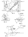
- FIG. 1 is a simplified elevational view of a seismic vibrator apparatus in accordance with the preferred embodiment of this invention with associated equipment shown in block form.
- FIG. is a top plan view of the vibrator apparatus shown in FIG. 1.
- FIG. 3 is a further top plan view of the vibrator apparatus in FIG. 1 with a rotated position of the turntable.
- FIG. 4 is a, detailed cutaway view of the ball and socket coupling means utilized with the vibrator apparatus of this invention.
- FIG. 5 is a schematic plan view of the apparatus of this invention illustrating its orientation with respect to a seismic line.
- FIG. 6 is a schematic representation of a typical mode of deployment of the vibrator apparatus of this invention illustrating the vector path of the apparatus in relation to the seismic line of FIG. 5.
- Referring now to FIG. 1, an apparatus is shown for practicing the invention utilizing a single vibrating mass.
Cylindrical vibrator assembly 10 may be of the type utilizing a reaction mass mounted for reciprocal motion on a double rod end piston under hydraulic control, all as well known to the art. An example of such a device is fully described and shown in U.S. Patent No. 3,159,233 in the name of F. Clynch et al, filed on December 1, 1964. Thus, reaction mass 11 is slidably mounted on a double rod end piston (not shown) having outwardly projectingrod ends base plate 12 thus transferring seismic vibrations into the earth. The manner of attachment of the vibrating means 10 to thebase plate 12 and the means for adjustment of the vibratory axis of the vibrating means 10 will be more particularly described below. - A ball fixed to
lower rod end 13 is recessed withinsocket 16 which is embedded in or otherwise secured to the surface ofbase plate 12.Ball 15 is rotatable in any direction about its center and therefore constitutes a "universal" pivot forvibration assembly 10. - With additional reference to FIG. 2, adjustment of the vector path of
vibrator assembly 10 is preferably accomplished with the aid ofturntable 17 mounted horizontally on raisedbed 18 carried uponframe 19 of any suitable transport vehicle (not shown).Turntable 17 is provided with aradial slot 21 through which theupper rod end 14 ofassembly 10 extends in slidable relation.Hydraulic cylinder 24 is mounted onturntable 17 by means of abracket 25 so that its piston rod 2ii is aligned withslot 21, the external end ofrod 26 being pivotally interconnected with acylindrical sleeve 25 surroundingupper rod end 14. Movement ofpiston rod 26 slides upper rod end 14 alongslot 21, thereby causingvibrational axis 29 ofassembly 10 to pivot aboutball 15 so thataxis 29 assumes any desired angle α with respect to a vertical position. - Rotation of
turntable 17 is provided throughdrive gear 30 andchain drive 31 operated byreversible motor 32 situated beneathbed 18. Suitable means are provided such as a dependent flange (not shown) for rotatably anchoringturntable 17 tobed 18. As best seen with reference to FIG. 3turntable slot 21 can in this manner be rotated through any desired angle ¡1 so thatslot 21 assumes any desired azimuthal position. This in turn causes a corresponding rotation of thevibrational axis 29 ofassembly 10 accompanied by corresponding pivotal movement aboutball 15. - The above-described angular adjustments through angles α and β may be performed sequentially or simultaneously. If desired such steps may be accomplished automatically through control means well known to the art.
- With particular reference to FIG. 4 it is noted that
socket 16 is provided with an upwardly opening inverted cone-shaped aperture 33 which subtends a solid angle sufficient to accommodate any desired pivotal movement ofvibrational axis 29 ofvibrator assembly 10. The circumference ofball 15 is larger than the diameter ofaperture 33 at its lower end. Thusball 15 is securely captured withinsocket 16 and faithfully transmits tobase p'late 12 the vibratory motion ofassembly 10 in both up and down directions. An advantage of this design is thatvibrator assembly 10 may be tilted in any direction from the vertical directly to a desired vector path or alternatively this path may be arrived at by rotation about two different axes. Thus the coupling provided byball 15 andsocket 16 is compatible with a variety of means for application of the necessary forces to effect adjustment of thevibrational axis 29. Regardless of the means selected for such adjustment, since no intermediate movable element separatesvibrator assembly 10 andbase plate 12, any possible mechanical misalignment resulting from the use of such element is avoided. This lessens or eliminates one source of possible attenuation or distortion of the seismic signal to be generated. It should be emphasized thatball 15 may be either a complete sphere or of other shape provided the surface thereof interfacing withsocket 16 is itself substantially spherical. Suitable bearing means whether liquid or solid may be applied between such interfacing surfaces to insure ease of adjustment of the position ofassembly 10. - In order to apply an appropriate static load to
base plate 12 and to avoid lateral shifting thereof in response to non-vertical forces imposed byvibrator assembly 10,base plate 12 is interconnected withvehicle frame 19 by means of adjustablehydraulic support members 40. By extendingsupport members 40 one can shift the weight of the transport vehicle entirely or in part from its spring suspension and its tires so as to bear directly upon and stabilizebase plate 12. - In operation one determines the desired vector path for
assembly 10 with respect to a seismic line. As an illustration, as shown in FIG. 5 one can align the transport vehicle so that it extends along a perpendicular 46 toseismic line 47 terminating in remote three-elementorthogonal geophone 48. In this way rotation ofslot 21 through any angle can establish the desired angular relation toline 47. As seen in the example of FIG. 6vibratory axis 29 ofassembly 10 lies at angle α to thevertical direction 49 so that the vector path ofassembly 10 falls withinvertical plane 50. Sinceplane 50 is at an acute angle β with regard toseismie line 47, vibratory motion ofassembly 10 will inject energy into the earth atseismic source point 52 which has components of P, SH and SV waves which may be sensed by the respective elements oforthogonal geophone 48. It is clear that the relative amplitudes of these waves may be adjusted as desired by controlling the values of angles α and β . As shown in the dotted outline ofupper rod end 14 ofassembly 10 in FIG. I one can if desired place thevibratory axis 29 ofassembly 10 in a vertical position so as to operate the apparatus as a pure P-wave vibrator. - If the angle α is limited to near vertical, i.e.; 5 degrees to not more than 25 degrees from vertical, the amplitude of the resultant shear wave energy for some near surface ground conditions is believed to retain the maximun value which can be achieved with a device of the character of
assembly 10. The increased compression of the ground resulting from such near vertical stress increases shear stiffness and strength in the ground where those properties are deficient. If, in use, the frictional coupling betweenbase plate 12 and the earth is broken by continued reciprocal motion ofassembly 10, the underside ofbase plate 12 may be provided with inverted pyramidal cleats (not shown). Such coupling devices are well known as described, for example, in United States Patent No. 3,1.59,232 issued to D. W. Fair on December 1, 1964. - Frequency and sweep wave control of the apparatus of this invention may be accomplished in a manner well known to those skilled in this art utilizing hydraulic supply 60 and control valves 62.
Servo valves 64 may then be operated by signals fromsweep control 66 so as to provide reciprocation of the internal reaction mass withinassembly 10 and produce corresponding vibrational motion ofbase plate 12 for coupling into the earth. - It should be understood that the particular form of vibrator described in this application as well as the means for adjustment of the
vibratory axis 29 ofvibrator assembly 10 are illustrative only and not to be regarded in any sense as limiting the scope of the apparatus of this invention as more particularly set forth in the appended claims.
Claims (5)
Applications Claiming Priority (2)
| Application Number | Priority Date | Filing Date | Title |
|---|---|---|---|
| US818199 | 1986-01-13 | ||
| US06/818,199 US4662473A (en) | 1986-01-13 | 1986-01-13 | Vibratory seismic source for generating combined compressional and shear waves |
Publications (3)
| Publication Number | Publication Date |
|---|---|
| EP0230372A2 true EP0230372A2 (en) | 1987-07-29 |
| EP0230372A3 EP0230372A3 (en) | 1987-12-23 |
| EP0230372B1 EP0230372B1 (en) | 1990-09-26 |
Family
ID=25224935
Family Applications (1)
| Application Number | Title | Priority Date | Filing Date |
|---|---|---|---|
| EP87300277A Expired - Lifetime EP0230372B1 (en) | 1986-01-13 | 1987-01-13 | Vibratory seismic source for generating combined compressional and shear waves |
Country Status (3)
| Country | Link |
|---|---|
| US (1) | US4662473A (en) |
| EP (1) | EP0230372B1 (en) |
| DE (1) | DE3765125D1 (en) |
Cited By (4)
| Publication number | Priority date | Publication date | Assignee | Title |
|---|---|---|---|---|
| EP0275782A1 (en) * | 1986-12-23 | 1988-07-27 | Institut Français du Pétrole | Apparatus for a combined generation of S and P waves in the soil in a plurality of different directions |
| GB2186368B (en) * | 1986-02-06 | 1990-02-14 | Atlantic Richfield Co | Vibratory seismic source for generating combined compressional and shear waves |
| FR2671638A1 (en) * | 1991-01-16 | 1992-07-17 | Staron Philippe | Method for detecting mechanical discontinuities in a medium to be explored |
| US6466859B1 (en) | 1998-06-04 | 2002-10-15 | Yamaha Motor Co Ltd | Control system |
Families Citing this family (11)
| Publication number | Priority date | Publication date | Assignee | Title |
|---|---|---|---|---|
| US4921067A (en) * | 1975-10-23 | 1990-05-01 | Shear Wave Technology | Self-propelled percussion unit and method of using same |
| US4848512A (en) * | 1988-11-10 | 1989-07-18 | Atlantic Richfield Company | Vibratory seismic source |
| US4967870A (en) * | 1989-01-09 | 1990-11-06 | Atlantic Richfield Company | Alignment restoration means for use in seismic apparatus |
| US4853907A (en) * | 1989-02-17 | 1989-08-01 | Atlantic Richfield Company | Inclinable vibratory seismic source |
| US4980874A (en) * | 1989-05-31 | 1990-12-25 | Atlantic Richfield Company | Method and apparatus for maximizing seismic shear wave production |
| US5000285A (en) * | 1990-02-28 | 1991-03-19 | Atlantic Richfield Company | Apparatus for imparting seismic signals into the earth |
| US5252785A (en) * | 1992-01-07 | 1993-10-12 | Industrial Vehicles International | Broad band seismic vibrator |
| US5666328A (en) * | 1996-10-18 | 1997-09-09 | I/O Exploration Products (U.S.A.), Inc. | Three axis seismic vibrator |
| US6065562A (en) * | 1998-07-27 | 2000-05-23 | Industrial Vehicles International, Inc. | System for imparting compressional and shear waves into the earth |
| DE102004014722B3 (en) * | 2004-03-25 | 2005-12-29 | Geoforschungszentrum Potsdam | Seismic source for geological and building investigations has oblique gas springs and separate flat transmission unit |
| EP3256837B1 (en) * | 2016-02-26 | 2020-09-23 | Csir | Accelerated pavement testing |
Citations (5)
| Publication number | Priority date | Publication date | Assignee | Title |
|---|---|---|---|---|
| US4059820A (en) * | 1975-11-21 | 1977-11-22 | Environmental Research Institute Of Michigan | Seismic wave generator and method of geophysical prospecting using the same |
| US4321981A (en) * | 1980-02-11 | 1982-03-30 | Conoco, Inc. | Combination shear wave and compressional wave seismic energy vibrator |
| US4354572A (en) * | 1978-11-27 | 1982-10-19 | Mapco, Inc. | Portable seismic energy source |
| EP0101331A2 (en) * | 1982-07-19 | 1984-02-22 | Institut Français du Pétrole | Apparatus for exciting acoustic wave generation in the soil |
| EP0155667A2 (en) * | 1984-03-19 | 1985-09-25 | Bolt Technology Corporation | Apparatus for generating shear waves and compression waves inthe earth for seismic surveying |
Family Cites Families (8)
| Publication number | Priority date | Publication date | Assignee | Title |
|---|---|---|---|---|
| US3159232A (en) * | 1962-11-14 | 1964-12-01 | Continental Oil Co | Shear wave transducer |
| US3282372A (en) * | 1962-11-14 | 1966-11-01 | Continental Oil Co | Direct drive method and apparatus for generating seismic vibratory signals |
| US3159233A (en) * | 1962-11-14 | 1964-12-01 | Continental Oil Co | Seismic transducer construction |
| US3277977A (en) * | 1963-10-28 | 1966-10-11 | Pan American Petroleum Corp | Seismic surveying with multiple falling weights |
| US4143736A (en) * | 1977-11-03 | 1979-03-13 | Continental Oil Company | Seismic transducer construction |
| US4291780A (en) * | 1979-02-13 | 1981-09-29 | Earl Fulkerson | Apparatus for wires in the ground |
| US4446742A (en) * | 1982-01-18 | 1984-05-08 | Structural Dynamics Research Corporation | Motion transmission limiting apparatus |
| US4537077A (en) * | 1984-02-08 | 1985-08-27 | Mts Systems Corporation | Load dynamics compensation circuit for servohydraulic control systems |
-
1986
- 1986-01-13 US US06/818,199 patent/US4662473A/en not_active Expired - Fee Related
-
1987
- 1987-01-13 EP EP87300277A patent/EP0230372B1/en not_active Expired - Lifetime
- 1987-01-13 DE DE8787300277T patent/DE3765125D1/en not_active Expired - Fee Related
Patent Citations (5)
| Publication number | Priority date | Publication date | Assignee | Title |
|---|---|---|---|---|
| US4059820A (en) * | 1975-11-21 | 1977-11-22 | Environmental Research Institute Of Michigan | Seismic wave generator and method of geophysical prospecting using the same |
| US4354572A (en) * | 1978-11-27 | 1982-10-19 | Mapco, Inc. | Portable seismic energy source |
| US4321981A (en) * | 1980-02-11 | 1982-03-30 | Conoco, Inc. | Combination shear wave and compressional wave seismic energy vibrator |
| EP0101331A2 (en) * | 1982-07-19 | 1984-02-22 | Institut Français du Pétrole | Apparatus for exciting acoustic wave generation in the soil |
| EP0155667A2 (en) * | 1984-03-19 | 1985-09-25 | Bolt Technology Corporation | Apparatus for generating shear waves and compression waves inthe earth for seismic surveying |
Cited By (5)
| Publication number | Priority date | Publication date | Assignee | Title |
|---|---|---|---|---|
| GB2186368B (en) * | 1986-02-06 | 1990-02-14 | Atlantic Richfield Co | Vibratory seismic source for generating combined compressional and shear waves |
| EP0275782A1 (en) * | 1986-12-23 | 1988-07-27 | Institut Français du Pétrole | Apparatus for a combined generation of S and P waves in the soil in a plurality of different directions |
| US4850451A (en) * | 1986-12-23 | 1989-07-25 | Institut Francais Du Petrole | Device for generating in the ground both transverse and longitudinal acoustic waves in a plurality of different directions |
| FR2671638A1 (en) * | 1991-01-16 | 1992-07-17 | Staron Philippe | Method for detecting mechanical discontinuities in a medium to be explored |
| US6466859B1 (en) | 1998-06-04 | 2002-10-15 | Yamaha Motor Co Ltd | Control system |
Also Published As
| Publication number | Publication date |
|---|---|
| EP0230372A3 (en) | 1987-12-23 |
| DE3765125D1 (en) | 1990-10-31 |
| EP0230372B1 (en) | 1990-09-26 |
| US4662473A (en) | 1987-05-05 |
Similar Documents
| Publication | Publication Date | Title |
|---|---|---|
| US4662473A (en) | Vibratory seismic source for generating combined compressional and shear waves | |
| US4805725A (en) | Nondestructive downhole seismic vibrator source and processes of utilizing the vibrator to obtain information about geologic formations | |
| US5823785A (en) | Simulator for pipe welding | |
| US4853907A (en) | Inclinable vibratory seismic source | |
| US4972930A (en) | Dynamically adjustable rotary unbalance shaker | |
| CN110542529B (en) | Oil tank shaking and vibrating test device | |
| US4655314A (en) | Vibratory seismic source for generating combined compressional and shear waves | |
| EP0444802A2 (en) | Apparatus for imparting seismic signals into the earth | |
| US5666328A (en) | Three axis seismic vibrator | |
| US4719607A (en) | Full wave field vibratory seismic source | |
| US4388981A (en) | Variable cylinder hydraulic vibrator and control system | |
| US4848512A (en) | Vibratory seismic source | |
| US4660675A (en) | Vibratory seismic source for generating combined compressional and shear waves | |
| EP0278152B1 (en) | Telescoping tube omni-directional shear wave vibrator | |
| US4867096A (en) | Tubular shear wave source | |
| US4980874A (en) | Method and apparatus for maximizing seismic shear wave production | |
| US5187331A (en) | SH wave generator | |
| US3352369A (en) | Sonic method and apparatus for driving anchors, anchor posts and the like | |
| US4635747A (en) | Marine seismic vibrator having support structure including vibration isolators | |
| US4804062A (en) | Baseplate assembly for seismic wave generator | |
| JPH0868717A (en) | Shaker system for bridge | |
| USRE32995E (en) | Variable cylinder hydraulic vibrator and control system | |
| CN213255661U (en) | Double-mass circular vibrating screen | |
| SU741524A1 (en) | Vibration exciter | |
| US4724532A (en) | Vibrator response linearization circuit |
Legal Events
| Date | Code | Title | Description |
|---|---|---|---|
| PUAI | Public reference made under article 153(3) epc to a published international application that has entered the european phase |
Free format text: ORIGINAL CODE: 0009012 |
|
| AK | Designated contracting states |
Kind code of ref document: A2 Designated state(s): DE FR GB |
|
| PUAL | Search report despatched |
Free format text: ORIGINAL CODE: 0009013 |
|
| AK | Designated contracting states |
Kind code of ref document: A3 Designated state(s): DE FR GB |
|
| 17P | Request for examination filed |
Effective date: 19880622 |
|
| 17Q | First examination report despatched |
Effective date: 19890724 |
|
| GRAA | (expected) grant |
Free format text: ORIGINAL CODE: 0009210 |
|
| AK | Designated contracting states |
Kind code of ref document: B1 Designated state(s): DE FR GB |
|
| REF | Corresponds to: |
Ref document number: 3765125 Country of ref document: DE Date of ref document: 19901031 |
|
| ET | Fr: translation filed | ||
| PLBE | No opposition filed within time limit |
Free format text: ORIGINAL CODE: 0009261 |
|
| STAA | Information on the status of an ep patent application or granted ep patent |
Free format text: STATUS: NO OPPOSITION FILED WITHIN TIME LIMIT |
|
| 26N | No opposition filed | ||
| PGFP | Annual fee paid to national office [announced via postgrant information from national office to epo] |
Ref country code: GB Payment date: 19930105 Year of fee payment: 7 |
|
| PGFP | Annual fee paid to national office [announced via postgrant information from national office to epo] |
Ref country code: FR Payment date: 19930126 Year of fee payment: 7 |
|
| PGFP | Annual fee paid to national office [announced via postgrant information from national office to epo] |
Ref country code: DE Payment date: 19930129 Year of fee payment: 7 |
|
| PG25 | Lapsed in a contracting state [announced via postgrant information from national office to epo] |
Ref country code: GB Effective date: 19940113 |
|
| GBPC | Gb: european patent ceased through non-payment of renewal fee |
Effective date: 19940113 |
|
| PG25 | Lapsed in a contracting state [announced via postgrant information from national office to epo] |
Ref country code: FR Effective date: 19940930 |
|
| PG25 | Lapsed in a contracting state [announced via postgrant information from national office to epo] |
Ref country code: DE Effective date: 19941001 |
|
| REG | Reference to a national code |
Ref country code: FR Ref legal event code: ST |