EP0229325B1 - Method of manufacturing a corrosion resistant steel component - Google Patents
Method of manufacturing a corrosion resistant steel component Download PDFInfo
- Publication number
- EP0229325B1 EP0229325B1 EP86117233A EP86117233A EP0229325B1 EP 0229325 B1 EP0229325 B1 EP 0229325B1 EP 86117233 A EP86117233 A EP 86117233A EP 86117233 A EP86117233 A EP 86117233A EP 0229325 B1 EP0229325 B1 EP 0229325B1
- Authority
- EP
- European Patent Office
- Prior art keywords
- component
- oxidising
- iron
- effected
- layer
- Prior art date
- Legal status (The legal status is an assumption and is not a legal conclusion. Google has not performed a legal analysis and makes no representation as to the accuracy of the status listed.)
- Expired - Lifetime
Links
- 238000004519 manufacturing process Methods 0.000 title claims description 7
- 239000010935 stainless steel Substances 0.000 title description 2
- 238000010438 heat treatment Methods 0.000 claims description 30
- 238000000034 method Methods 0.000 claims description 29
- 239000000203 mixture Substances 0.000 claims description 29
- 239000002344 surface layer Substances 0.000 claims description 27
- XEEYBQQBJWHFJM-UHFFFAOYSA-N Iron Chemical compound [Fe] XEEYBQQBJWHFJM-UHFFFAOYSA-N 0.000 claims description 26
- 229910000704 hexaferrum Inorganic materials 0.000 claims description 24
- 150000004767 nitrides Chemical class 0.000 claims description 20
- UQSXHKLRYXJYBZ-UHFFFAOYSA-N Iron oxide Chemical compound [Fe]=O UQSXHKLRYXJYBZ-UHFFFAOYSA-N 0.000 claims description 15
- 238000005260 corrosion Methods 0.000 claims description 15
- 230000007797 corrosion Effects 0.000 claims description 14
- 229910052742 iron Inorganic materials 0.000 claims description 13
- SZVJSHCCFOBDDC-UHFFFAOYSA-N ferrosoferric oxide Chemical compound O=[Fe]O[Fe]O[Fe]=O SZVJSHCCFOBDDC-UHFFFAOYSA-N 0.000 claims description 12
- 238000005121 nitriding Methods 0.000 claims description 12
- 229910000851 Alloy steel Inorganic materials 0.000 claims description 7
- 230000003746 surface roughness Effects 0.000 claims description 5
- MBMLMWLHJBBADN-UHFFFAOYSA-N Ferrous sulfide Chemical compound [Fe]=S MBMLMWLHJBBADN-UHFFFAOYSA-N 0.000 claims description 4
- 238000002485 combustion reaction Methods 0.000 claims description 2
- NINIDFKCEFEMDL-UHFFFAOYSA-N Sulfur Chemical compound [S] NINIDFKCEFEMDL-UHFFFAOYSA-N 0.000 claims 1
- 239000005864 Sulphur Substances 0.000 claims 1
- 150000001875 compounds Chemical class 0.000 claims 1
- IJGRMHOSHXDMSA-UHFFFAOYSA-N Atomic nitrogen Chemical compound N#N IJGRMHOSHXDMSA-UHFFFAOYSA-N 0.000 description 49
- 239000010410 layer Substances 0.000 description 31
- 238000010791 quenching Methods 0.000 description 31
- 239000003570 air Substances 0.000 description 27
- 150000003839 salts Chemical class 0.000 description 27
- 230000000171 quenching effect Effects 0.000 description 25
- 229910000831 Steel Inorganic materials 0.000 description 24
- 229910052757 nitrogen Inorganic materials 0.000 description 24
- 239000010959 steel Substances 0.000 description 24
- XLYOFNOQVPJJNP-UHFFFAOYSA-N water Substances O XLYOFNOQVPJJNP-UHFFFAOYSA-N 0.000 description 22
- 238000001816 cooling Methods 0.000 description 20
- 239000007789 gas Substances 0.000 description 20
- QVGXLLKOCUKJST-UHFFFAOYSA-N atomic oxygen Chemical compound [O] QVGXLLKOCUKJST-UHFFFAOYSA-N 0.000 description 17
- 239000001301 oxygen Substances 0.000 description 17
- 229910052760 oxygen Inorganic materials 0.000 description 17
- QGZKDVFQNNGYKY-UHFFFAOYSA-N Ammonia Chemical compound N QGZKDVFQNNGYKY-UHFFFAOYSA-N 0.000 description 16
- CURLTUGMZLYLDI-UHFFFAOYSA-N Carbon dioxide Chemical compound O=C=O CURLTUGMZLYLDI-UHFFFAOYSA-N 0.000 description 14
- 230000003647 oxidation Effects 0.000 description 12
- 238000007254 oxidation reaction Methods 0.000 description 12
- 239000007921 spray Substances 0.000 description 12
- 239000000839 emulsion Substances 0.000 description 10
- 230000008569 process Effects 0.000 description 10
- 238000011282 treatment Methods 0.000 description 9
- 229910021529 ammonia Inorganic materials 0.000 description 8
- 230000000694 effects Effects 0.000 description 8
- 239000001569 carbon dioxide Substances 0.000 description 7
- 229910002092 carbon dioxide Inorganic materials 0.000 description 7
- 238000012360 testing method Methods 0.000 description 7
- KWYUFKZDYYNOTN-UHFFFAOYSA-M Potassium hydroxide Chemical compound [OH-].[K+] KWYUFKZDYYNOTN-UHFFFAOYSA-M 0.000 description 6
- 238000006073 displacement reaction Methods 0.000 description 6
- OKTJSMMVPCPJKN-UHFFFAOYSA-N Carbon Chemical compound [C] OKTJSMMVPCPJKN-UHFFFAOYSA-N 0.000 description 5
- HEMHJVSKTPXQMS-UHFFFAOYSA-M Sodium hydroxide Chemical compound [OH-].[Na+] HEMHJVSKTPXQMS-UHFFFAOYSA-M 0.000 description 5
- UGFAIRIUMAVXCW-UHFFFAOYSA-N Carbon monoxide Chemical compound [O+]#[C-] UGFAIRIUMAVXCW-UHFFFAOYSA-N 0.000 description 4
- RAHZWNYVWXNFOC-UHFFFAOYSA-N Sulphur dioxide Chemical compound O=S=O RAHZWNYVWXNFOC-UHFFFAOYSA-N 0.000 description 4
- 229910052799 carbon Inorganic materials 0.000 description 4
- 229910002091 carbon monoxide Inorganic materials 0.000 description 4
- VNWKTOKETHGBQD-UHFFFAOYSA-N methane Chemical compound C VNWKTOKETHGBQD-UHFFFAOYSA-N 0.000 description 4
- 230000001590 oxidative effect Effects 0.000 description 4
- 239000006104 solid solution Substances 0.000 description 4
- VYZAMTAEIAYCRO-UHFFFAOYSA-N Chromium Chemical compound [Cr] VYZAMTAEIAYCRO-UHFFFAOYSA-N 0.000 description 3
- UFHFLCQGNIYNRP-UHFFFAOYSA-N Hydrogen Chemical compound [H][H] UFHFLCQGNIYNRP-UHFFFAOYSA-N 0.000 description 3
- 229910001209 Low-carbon steel Inorganic materials 0.000 description 3
- 238000010521 absorption reaction Methods 0.000 description 3
- 229910052804 chromium Inorganic materials 0.000 description 3
- 239000011651 chromium Substances 0.000 description 3
- 239000001257 hydrogen Substances 0.000 description 3
- 229910052739 hydrogen Inorganic materials 0.000 description 3
- 229910052751 metal Inorganic materials 0.000 description 3
- 239000002184 metal Substances 0.000 description 3
- 150000002739 metals Chemical class 0.000 description 3
- 238000002156 mixing Methods 0.000 description 3
- 239000007764 o/w emulsion Substances 0.000 description 3
- 238000007747 plating Methods 0.000 description 3
- VWDWKYIASSYTQR-UHFFFAOYSA-N sodium nitrate Chemical compound [Na+].[O-][N+]([O-])=O VWDWKYIASSYTQR-UHFFFAOYSA-N 0.000 description 3
- 239000006096 absorbing agent Substances 0.000 description 2
- 238000004458 analytical method Methods 0.000 description 2
- 238000004299 exfoliation Methods 0.000 description 2
- 238000001659 ion-beam spectroscopy Methods 0.000 description 2
- 238000005259 measurement Methods 0.000 description 2
- 230000007246 mechanism Effects 0.000 description 2
- 125000004433 nitrogen atom Chemical group N* 0.000 description 2
- 238000007517 polishing process Methods 0.000 description 2
- 230000001681 protective effect Effects 0.000 description 2
- 230000035939 shock Effects 0.000 description 2
- 238000010583 slow cooling Methods 0.000 description 2
- 239000000243 solution Substances 0.000 description 2
- UTPYTEWRMXITIN-YDWXAUTNSA-N 1-methyl-3-[(e)-[(3e)-3-(methylcarbamothioylhydrazinylidene)butan-2-ylidene]amino]thiourea Chemical compound CNC(=S)N\N=C(/C)\C(\C)=N\NC(=S)NC UTPYTEWRMXITIN-YDWXAUTNSA-N 0.000 description 1
- DGAQECJNVWCQMB-PUAWFVPOSA-M Ilexoside XXIX Chemical compound C[C@@H]1CC[C@@]2(CC[C@@]3(C(=CC[C@H]4[C@]3(CC[C@@H]5[C@@]4(CC[C@@H](C5(C)C)OS(=O)(=O)[O-])C)C)[C@@H]2[C@]1(C)O)C)C(=O)O[C@H]6[C@@H]([C@H]([C@@H]([C@H](O6)CO)O)O)O.[Na+] DGAQECJNVWCQMB-PUAWFVPOSA-M 0.000 description 1
- SEQUALWBCFCDGP-UHFFFAOYSA-N [C].[N].[Fe] Chemical compound [C].[N].[Fe] SEQUALWBCFCDGP-UHFFFAOYSA-N 0.000 description 1
- 239000002250 absorbent Substances 0.000 description 1
- 230000002745 absorbent Effects 0.000 description 1
- 229910045601 alloy Inorganic materials 0.000 description 1
- 239000000956 alloy Substances 0.000 description 1
- 239000012080 ambient air Substances 0.000 description 1
- 238000013459 approach Methods 0.000 description 1
- XKRFYHLGVUSROY-UHFFFAOYSA-N argon Substances [Ar] XKRFYHLGVUSROY-UHFFFAOYSA-N 0.000 description 1
- 229910052786 argon Inorganic materials 0.000 description 1
- -1 argon ions Chemical class 0.000 description 1
- 230000008901 benefit Effects 0.000 description 1
- 230000015572 biosynthetic process Effects 0.000 description 1
- 150000005323 carbonate salts Chemical class 0.000 description 1
- 238000005255 carburizing Methods 0.000 description 1
- 231100000481 chemical toxicant Toxicity 0.000 description 1
- 239000011248 coating agent Substances 0.000 description 1
- 238000000576 coating method Methods 0.000 description 1
- 239000000356 contaminant Substances 0.000 description 1
- 238000005336 cracking Methods 0.000 description 1
- 238000005238 degreasing Methods 0.000 description 1
- 230000001419 dependent effect Effects 0.000 description 1
- 238000013461 design Methods 0.000 description 1
- 229910003460 diamond Inorganic materials 0.000 description 1
- 239000010432 diamond Substances 0.000 description 1
- 239000012153 distilled water Substances 0.000 description 1
- 238000010894 electron beam technology Methods 0.000 description 1
- 230000001747 exhibiting effect Effects 0.000 description 1
- 238000002474 experimental method Methods 0.000 description 1
- 238000007730 finishing process Methods 0.000 description 1
- 239000007792 gaseous phase Substances 0.000 description 1
- 239000000383 hazardous chemical Substances 0.000 description 1
- 239000001307 helium Substances 0.000 description 1
- 229910052734 helium Inorganic materials 0.000 description 1
- SWQJXJOGLNCZEY-UHFFFAOYSA-N helium atom Chemical compound [He] SWQJXJOGLNCZEY-UHFFFAOYSA-N 0.000 description 1
- 238000007654 immersion Methods 0.000 description 1
- 230000006872 improvement Effects 0.000 description 1
- 238000010884 ion-beam technique Methods 0.000 description 1
- 150000002500 ions Chemical class 0.000 description 1
- 229910001337 iron nitride Inorganic materials 0.000 description 1
- 238000003754 machining Methods 0.000 description 1
- 239000000463 material Substances 0.000 description 1
- 239000011159 matrix material Substances 0.000 description 1
- 238000012986 modification Methods 0.000 description 1
- 230000004048 modification Effects 0.000 description 1
- 150000002825 nitriles Chemical class 0.000 description 1
- JCXJVPUVTGWSNB-UHFFFAOYSA-N nitrogen dioxide Inorganic materials O=[N]=O JCXJVPUVTGWSNB-UHFFFAOYSA-N 0.000 description 1
- 125000004430 oxygen atom Chemical group O* 0.000 description 1
- 239000003208 petroleum Substances 0.000 description 1
- 239000012071 phase Substances 0.000 description 1
- GKKCIDNWFBPDBW-UHFFFAOYSA-M potassium cyanate Chemical compound [K]OC#N GKKCIDNWFBPDBW-UHFFFAOYSA-M 0.000 description 1
- NNFCIKHAZHQZJG-UHFFFAOYSA-N potassium cyanide Chemical compound [K+].N#[C-] NNFCIKHAZHQZJG-UHFFFAOYSA-N 0.000 description 1
- 238000012545 processing Methods 0.000 description 1
- 239000011833 salt mixture Substances 0.000 description 1
- 239000002356 single layer Substances 0.000 description 1
- 239000004317 sodium nitrate Substances 0.000 description 1
- 235000010344 sodium nitrate Nutrition 0.000 description 1
- 238000004544 sputter deposition Methods 0.000 description 1
- 239000004291 sulphur dioxide Substances 0.000 description 1
- 235000010269 sulphur dioxide Nutrition 0.000 description 1
- 238000004381 surface treatment Methods 0.000 description 1
- 238000010301 surface-oxidation reaction Methods 0.000 description 1
- 231100000331 toxic Toxicity 0.000 description 1
- 230000002588 toxic effect Effects 0.000 description 1
- 239000003440 toxic substance Substances 0.000 description 1
Images

Classifications
-
- C—CHEMISTRY; METALLURGY
- C21—METALLURGY OF IRON
- C21D—MODIFYING THE PHYSICAL STRUCTURE OF FERROUS METALS; GENERAL DEVICES FOR HEAT TREATMENT OF FERROUS OR NON-FERROUS METALS OR ALLOYS; MAKING METAL MALLEABLE, e.g. BY DECARBURISATION OR TEMPERING
- C21D9/00—Heat treatment, e.g. annealing, hardening, quenching or tempering, adapted for particular articles; Furnaces therefor
- C21D9/0068—Heat treatment, e.g. annealing, hardening, quenching or tempering, adapted for particular articles; Furnaces therefor for particular articles not mentioned below
-
- C—CHEMISTRY; METALLURGY
- C23—COATING METALLIC MATERIAL; COATING MATERIAL WITH METALLIC MATERIAL; CHEMICAL SURFACE TREATMENT; DIFFUSION TREATMENT OF METALLIC MATERIAL; COATING BY VACUUM EVAPORATION, BY SPUTTERING, BY ION IMPLANTATION OR BY CHEMICAL VAPOUR DEPOSITION, IN GENERAL; INHIBITING CORROSION OF METALLIC MATERIAL OR INCRUSTATION IN GENERAL
- C23C—COATING METALLIC MATERIAL; COATING MATERIAL WITH METALLIC MATERIAL; SURFACE TREATMENT OF METALLIC MATERIAL BY DIFFUSION INTO THE SURFACE, BY CHEMICAL CONVERSION OR SUBSTITUTION; COATING BY VACUUM EVAPORATION, BY SPUTTERING, BY ION IMPLANTATION OR BY CHEMICAL VAPOUR DEPOSITION, IN GENERAL
- C23C8/00—Solid state diffusion of only non-metal elements into metallic material surfaces; Chemical surface treatment of metallic material by reaction of the surface with a reactive gas, leaving reaction products of surface material in the coating, e.g. conversion coatings, passivation of metals
- C23C8/06—Solid state diffusion of only non-metal elements into metallic material surfaces; Chemical surface treatment of metallic material by reaction of the surface with a reactive gas, leaving reaction products of surface material in the coating, e.g. conversion coatings, passivation of metals using gases
- C23C8/08—Solid state diffusion of only non-metal elements into metallic material surfaces; Chemical surface treatment of metallic material by reaction of the surface with a reactive gas, leaving reaction products of surface material in the coating, e.g. conversion coatings, passivation of metals using gases only one element being applied
- C23C8/24—Nitriding
- C23C8/26—Nitriding of ferrous surfaces
-
- C—CHEMISTRY; METALLURGY
- C23—COATING METALLIC MATERIAL; COATING MATERIAL WITH METALLIC MATERIAL; CHEMICAL SURFACE TREATMENT; DIFFUSION TREATMENT OF METALLIC MATERIAL; COATING BY VACUUM EVAPORATION, BY SPUTTERING, BY ION IMPLANTATION OR BY CHEMICAL VAPOUR DEPOSITION, IN GENERAL; INHIBITING CORROSION OF METALLIC MATERIAL OR INCRUSTATION IN GENERAL
- C23C—COATING METALLIC MATERIAL; COATING MATERIAL WITH METALLIC MATERIAL; SURFACE TREATMENT OF METALLIC MATERIAL BY DIFFUSION INTO THE SURFACE, BY CHEMICAL CONVERSION OR SUBSTITUTION; COATING BY VACUUM EVAPORATION, BY SPUTTERING, BY ION IMPLANTATION OR BY CHEMICAL VAPOUR DEPOSITION, IN GENERAL
- C23C8/00—Solid state diffusion of only non-metal elements into metallic material surfaces; Chemical surface treatment of metallic material by reaction of the surface with a reactive gas, leaving reaction products of surface material in the coating, e.g. conversion coatings, passivation of metals
- C23C8/06—Solid state diffusion of only non-metal elements into metallic material surfaces; Chemical surface treatment of metallic material by reaction of the surface with a reactive gas, leaving reaction products of surface material in the coating, e.g. conversion coatings, passivation of metals using gases
- C23C8/34—Solid state diffusion of only non-metal elements into metallic material surfaces; Chemical surface treatment of metallic material by reaction of the surface with a reactive gas, leaving reaction products of surface material in the coating, e.g. conversion coatings, passivation of metals using gases more than one element being applied in more than one step
-
- C—CHEMISTRY; METALLURGY
- C23—COATING METALLIC MATERIAL; COATING MATERIAL WITH METALLIC MATERIAL; CHEMICAL SURFACE TREATMENT; DIFFUSION TREATMENT OF METALLIC MATERIAL; COATING BY VACUUM EVAPORATION, BY SPUTTERING, BY ION IMPLANTATION OR BY CHEMICAL VAPOUR DEPOSITION, IN GENERAL; INHIBITING CORROSION OF METALLIC MATERIAL OR INCRUSTATION IN GENERAL
- C23C—COATING METALLIC MATERIAL; COATING MATERIAL WITH METALLIC MATERIAL; SURFACE TREATMENT OF METALLIC MATERIAL BY DIFFUSION INTO THE SURFACE, BY CHEMICAL CONVERSION OR SUBSTITUTION; COATING BY VACUUM EVAPORATION, BY SPUTTERING, BY ION IMPLANTATION OR BY CHEMICAL VAPOUR DEPOSITION, IN GENERAL
- C23C8/00—Solid state diffusion of only non-metal elements into metallic material surfaces; Chemical surface treatment of metallic material by reaction of the surface with a reactive gas, leaving reaction products of surface material in the coating, e.g. conversion coatings, passivation of metals
- C23C8/80—After-treatment
Definitions
- This invention relates to a method of manufacturing a corrosion resistant steel component.
- the first salt bath heat treatment is effected for about 2 hours at 580°C in a potassium cyanide/potassium cyanate bath.
- the second heat treatment is effected by quenching the components at 400°C for about 10 minutes in a second salt bath containing sodium hydroxide, potassium hydroxide, and sodium nitrate. This is followed by water quenching of the component. If it is important to restore the oxidized surface of the product to its original finish, it may be necessary to effect a lapping operation at this stage followed by re-treatment in the oxidizing bath for 20 minutes at about 400°C again followed by water quenching.
- JP-A-48-75433 discloses a method of anti-corrosion surface treatment of steel where the steel is heat treated in a nitriding gaseous atmosphere in a furnace to produce an epsilon iron nitride or carbonitride surface layer thereon, and is then removed from the furnace and held in air whilst still hot for 60 to 120 seconds to produce a 2-3 ⁇ m Fe3O4 layer.
- the component may be allowed to cool in air or it may be cooled by immersion in oil after the Fe3O4 layer has been formed.
- GB-A-693715 discloses a process for finishing low carbon steel articles where the articles are heated in a case-hardening furnace to form a hardened surface thereon, quenched, drawn to reduce the surface hardness somewhat, and then tumbled until a polished surface is obtained.
- a method of manufacturing a corrosion resistant non-alloy steel component comprising the steps of heat treating a non-alloy steel component in a nitriding gaseous atmosphere to produce an epsilon iron nitride or iron carbonitride surface layer thereon; and subsequently oxidising the component to provide an oxide-rich surface layer, characterized in that between the heat treating and oxidising steps the component is cooled and mechanically surface finished.
- this step is typically effected at a temperature in the range of 550 to 720°C for up to 4 hours in an atmosphere of ammonia, ammonia and endothermic gas, ammonia and exothermic gas or ammonia and nitrogen, with the optional inclusion of at least one or carbon dioxide, carbon monoxide, air, water vapour and methane.
- ammonia, ammonia and endothermic gas, ammonia and exothermic gas or ammonia and nitrogen with the optional inclusion of at least one or carbon dioxide, carbon monoxide, air, water vapour and methane.
- exothermic gas and "endothermic gas” are well understood in the art. Carbon dioxide, carbon monoxide, air, water vapour and exothermic gas are oxidising gases.
- Carbon dioxide, methane and endothermic gas are carburizing gases. It is preferred to effect the heat treatment operation so that the epsilon iron nitride surface layer has a thickness of about 25 micrometres. Thicknesses greater than about 25 micrometre can lead to exfoliation or cracking of the surface layer. Typically, such a layer thickness of about 25 micrometres can be obtained by heat treatment at 660°C for 45 minutes. Such a layer thickness may also be produced by heat treatment of 570°C for 3 hours or at 610°C for 90 minutes. However, the heat treatment temperatures and times may be employed to produce layer thicknesses less than 25 micrometres, e.g. down to 15 micrometres. For example, heat treatment of 570°C for 2 hours can be employed to produce a layer thickness of 16 to 20 micrometres.
- Components produced by the method of the present invention have a fine surface finish without the need to have a wax protection system to give a good corrosion resistance.
- the component after being heat treated in the nitriding gaseous atmosphere, is cooled in any desired medium, and then subjected to a lapping or other mechanical surface finishing process to a surface roughness of, for example, not more than 0.2 micrometres R a .
- This lapping or polishing process will remove any oxide film which may have formed on the component, depending upon the medium used for cooling.
- the component can then be oxidised at a temperature of 300 to 600°C.
- the oxidising heat treatment is preferably effected at 350 to 450°C for about 15 to 5 minutes depending upon the temperature in unstripped exothermic gas.
- the component is preferably heat treated at 500 to 600°C, more preferably, 550 to 600°C followed by quenching to retain nitrogen in solid solution in the ferritic matrix of the steel microstructure.
- unstripped exothermic gas another type of oxidising atmosphere may be employed such as steam, air or other mixture of oxygen and nitrogen, carbon dioxide and nitrogen, or carbon dioxide alone or any mixture of these gases.
- Quenching is preferably effected into an oil/water emulsion.
- an aesthetically pleasing black finish is obtained. Quenching the component directly into an oil/water emulsion without the intermediate oxidation step does not give a black finish but a grey finish where the oxide layer is only 0.1 micrometres thick. However, quenching an already oxidised component into the oil/water emulsion does increase the degree of oxidation to a small extent and thereby darkens the colour.
- a steel component after having had an epsilon iron nitride surface layer formed thereon by heat treatment at 570°C for about 2 hours in an atmosphere 50% ammonia and 50% endothermic gas mixture is exposed to ambient air for two seconds to effect surface oxidation and then immersed in a bath of an oil-in-water emulsion which, in this embodiment, is produced by mixing a soluble oil sold under the trade mark EVCOQUENCH GW with water in an oil:water volume ratio of 1:6.
- the resultant product Since the component being quenched is at a temperature greater than 550°C, the resultant product has a good fatigue strength and yield strength in addition to having an aesthetically pleasing black surface with extremely good resistance to corrosion and good bearing properties in view of the absorption of oil into the surface.
- Components produced in accordance with the invention which have been cooled after exposure to the nitriding atmosphere, polished and then oxidised are more economical to manufacture than hard chromium plating which also suffers from the disadvantage of creating effluent disposal problems. Additionally the gaseous treatment is cheaper than the above-mentioned salt bath treatment, particularly since the latter requires the double oxidising step.
- Non-alloy steel components produced according to the present invention have a hard wear resistant layer and a surface having an extremely good resistance to humidity and salt spray corrosion. Such components also have a low coefficient of friction (similar to polished hard chromium plating) so that they are capable of being used in sliding applications. Further, such components possess a high surface tension which gives extremely low wettability which is of great help in a resisting humidity and salt spray corrosion attack and also have a pleasing aesthetic appearance (gloss blue/black according to the temperature employed in the oxidising treatment). Additionally, steel components which have been quenched from 550°C to keep nitrogen in solid solution also have good fatigue and yield strength properties.
- the method of the invention has the advantage that, being of an all gaseous nature, the effluent problems associated with the salt bath heat treatment process are avoided.
- the method of the invention can be performed by processors with modern gaseous atmosphere heat treatment plant without the requirement for further capital investment in plating or salt bath equipment.
- the surface layer portion is substantially free of nitrogen atoms.
- the surface layer portion wherein substantially all of the nitrogen atoms have been displaced by oxygen atoms extends for a depth of at least 0.2, more preferably at least 0.3, micrometre.
- the resistance of the oxidised surface to corrosion is explained by the predominance of iron oxide, mainly in the form of Fe304 down to a depth of at least 0.1 micrometre and sometimes down to more than 1 micrometre in depth. However, to avoid oxide exfoliation, it is preferred for iron oxide to be present down to a depth not exceeding 1 micrometre.
- the surface layer portion has a composition approaching that of Fe304 in the part of the surface layer portion immediately under the surface whilst, as the depth increases, the composition has an increasing Fe0 content.
- a surface layer can be produced by exposing the component having the epsilon iron nitride layer thereon to air before quenching in water/oil emulsion.
- the part of the surface layer portion immediately below the surface has a composition approaching that of Fe203 but, as the depth increases, the composition becomes progresssively closer to that of Fe304.
- Such composition can be produced by allowing the component having the epsilon iron nitride layer thereon to cool completely in air Attention is drawn to the disclosure in a Paper entitled “Reappraisal of Nitrocarburising and Nitriding when Applied to Design and Manufacture of Non-alloy Steel Automobile Components" by C. Dawes, D.F. Tranter, and C.G.Smith presented during a symposium entitled “Heat Treatment '79' organised by The Metals Society and American Society for Metals in Birmingham on 22nd to 24th May 1979.
- Air cooling of the material subsequent to gaseous heat treatment is mentioned in such Paper. However, this is not to be construed as meaning cooling in air, ie an oxidising atmosphere.
- air cooling was used as a term of art to mean slow cooling and to distinguish the cooling process from oil quenching which is a fast cooling process. In fact, the "air cooling” is more accurately described as "gas cooling” since cooling was effected in the same gaseous nitriding atmosphere used during the heat treatment step to produce the epsilon layer.
- the oil quenched samples were first vapour degreased and then all the test pieces were introduced into an Auger Electron Spectrometer which was evacuated down to a pressure of 1 x 10 ⁇ 8 torr and allowed to remain under this reduced pressure overnight to remove any gases which had been absorbed into the surface of the samples.
- the heat treatment process to which the samples were subjected is one which produces an epsilon iron carbonitride layer to a depth well in excess of 20 micrometres.
- the epsilon iron carbonitride layer consists of a porous and a non-porous region, the porous region extending from the surface of the sample downwardly to a depth of about 10 micrometres, and the non-porous region underlying this At a depth of 20 micrometres, the epsilon iron carbonitride layer has a typical elemental composition of 92% by weight of iron, 7.4% by weight of nitrogen, 0.4% by weight of carbon and 0.2% by weight of oxygen.
- the elemental composition for the whole layer is consistent with the epsilon iron carbonitride region of the ternary iron-carbon-nitrogen system defined by Naumann and Langescheid (Eisenblinncher 1965, 36,677).
- the layer of Sample 1 is also consistent with the idealized iron nitride formula Fe2N 1-x where x is 0 to 1, for the epsilon phase reported by Lightfoot and Jack in "Kinetics of Nitriding With and Without White Layer Formation" (Proceedings of Heat Treatment Conference 1973 organised by Heat Treatment and Joint Committee of the Iron and Steel Institute), the nitrogen content being between 7.5 and 11% by weight.
- Figures 1 to 4 are graphs plotting the iron and nitrogen, iron and oxygen, or iron, oxygen and nitrogen contents in a layer region of Samples 1 to 4 respectively.
- the layer region chosen is one which extends from 16 x 10 ⁇ 9 metres to about 400 x 10 ⁇ 9 metres from the surface.
- the first measurement plotted on the graph is that at 16 x 10 ⁇ 9 metres, the samples having been subjected to an initial ion sputtering technique to remove foreign contaminants from the outer surface.
- oxidation of the Samples after heat treatment either solely in air or initially in air and followed by quenching in the oil/water emulsion results in displacement of nitrogen by oxygen.
- Displacement of nitrogen is total in the outermost surface layers portions (i.e. down to a depth which may vary between 0.1 micrometre and 1 micrometre,) depending upon the time of exposure to air while the sample is hot before quenching, and also on the cooling rate in the quench. Partial displacement of the nitrogen continues in some instances to depths in excess of 1 micrometre.
- Samples 2 and 3 were corrosion resistant becauseof the predominance of iron oxide mainly in the form of Fe304 to depth of at least 0.1 micrometre and sometimes down to more than 1 micrometre in depth.
- the iron to oxygen ratio at the extreme surface indicates a composition approaching that of Fe203 but as the depth increases into the layer, the composition becomes progressively closer to that of Fe304.
- the iron to oxygen ratio suggests a structure close to Fe304 in the outer surface layer portions but increasing in Fe0 on progression inwards.
- the first four blocks relate to exposure of nitrocarburised component at above 550°C to air for the specified time, followed by quenching in a water/oil emulsion.
- the last block relates to quenching of a nitrocarburized component directly into oil without exposure to air.
- Steel components according to the present invention have a corrosion resistance which is superior even to components surface treated to produce an epsilon iron nitride surface layer, oil quenched, degreased (or slow cooled under a protective atmosphere) and then dipped in a de-watering oil so that the de-watering oil is absorbed into an absorbent outer portion of the epsilon iron nitride surface layer.
- Table 8 below compares the corrosion resistant properties of various types of steel component:- TABLE 8 SAMPLE NO SALT SPRAY RESISTANCE (HOURS) 1 0 2 17 3 96 4 150+
- the salt spray resistance was evaluated in a salt spray test in accordance with ATSM Standard B117-64 in which the component is exposed in a salt spray chamber maintained at 95+2-3°F to a salt spray prepared by dissolving 5+/- 1 parts by weight of salt in 95 parts of distilled water and adjusting the pH of the solution such that, when atomised at 95°F, the collect solution has a pH in range of 6.5 to 7.2 After removal from the salt spray test, the components are washed under running water, dried and the incidence of red rusting is assessed. Components exhibiting any red rusting are deemed to have failed.
- Sample 1 a plain, ie untreated steel component.
- Sample 2 a steel component having an epsilon iron nitride surface layer produced by the first-mentioned heat treating step in the method of the invention, followed by oil quenching and degreasing (or slow cooling under a protective atmosphere).
- Sample 3 the steel component of Sample 2 additionally dipped in a de-watering oil.
- Sample 4 the steel component having an epsilon iron nitride layer and an oxide-rich surface layer produced in accordance with the present invention after lapping the surface to a finish of 0.2 micrometres. It is to be noted that, in the case of Sample 4, the actual salt spray resistance figure depends upon the surface finish.
- the steel component treated is a shock absorber Piston rod with a final surface finish of 0.13 to 0.15 micrometres Ra.
- a shock absorber Piston rod with a final surface finish of 0.13 to 0.15 micrometres Ra.
- Such a component was found to have a salt spray resistance of 250 hours.
- the improvement in fatigue properties will become apparent from an examination of Table 9 below:- TABLE 9 SAMPLE ENDURANCE LIMIT AT 107 Cycles N/mm2 Plain Notched 5 250 190 6 440 350 7 260 195 8 435 345
- the fatigue property was evaluated using an NPL-type two point loading rotary beam machine employing standard 0.30" (7.6mm) diameter NPL test pieces.
- - Sample 5 an untreated steel component.
- Sample 6 a steel component which has an epsilon iron nitride surface layer formed thereon by heat treatment at 570°C for about 2 hours in an atmosphere of 50% ammonia and 50% endothermic gas mixture, followed by oil quenching.
- Sample 7 a steel component having an epsilon iron nitride layer produced as in Sample 6 above, and subsequently oxidised in a sodium/potassium hydroxide/sodium nitrate salt bath mixture (sold as "Degussa ABl salt") at a temperature of 400°C as recommended by the suppliers of the salt mixture.
- Sample 8 a steel component having an epsilon iron nitride surface layer formed by heat treatment as in Sample 6 but subsequently oxidised in steam at 540°C for 30 minutes, followed by oil quenching.
- a shock absorber piston rod having a length of 230mm, a diameter of 12.5 mm, and an initial surface roughness of 0.13 to 0.15 micrometres Ra was manufactured by machining a bar of low carbon steel (BS970-045M10) and was heat treated for two hours at 570°C in an atmosphere of 50% ammonia and 50% endothermic gas mixture (Carbon monoxide, carbon dioxide, nitrogen and hydrogen). The rod was then cooled slowly under the protection of the same atmosphere as used in the above mentioned heat treatment. The resultant rod had a 20 micrometre thick layer of epsilon iron nitride thereon and a surface roughness of 0.64 micrometres Ra.
- the rod was oxidised in an exothermic gas mixture containing its moisture of combustion for 10 minutes at 400°C to produce a 0.5 micrometre thick oxide-rich surface layer.
- the piston rod was then cooled by water quenching.
- the piston rod was found to have a salt spray resistance of 250 hours according to the above described salt spray test.
- the rod was oxidised for 15 minutes at 400°C in the exothermic gas mixture, but during the last 5 minutes of the 15 minute cycle, sulphur dioxide was introduced into the furnace in an amount such as to give a concentration of 0.25% by volume in the furnace atmosphere.
- sulphur dioxide was introduced into the furnace in an amount such as to give a concentration of 0.25% by volume in the furnace atmosphere.
- Such a technique caused about 1% of the iron oxide (Fe203) on the surface of the rod to be converted to iron sulphide which gave an aesthetically pleasing shiny black surface to the rod.
- the technique of sulphiding is not restricted to components in the form of damper rods and can be used in respect of any components on which it is desirable to have a black hard-wearing surface. With surface finishes greater than 0.25 micrometres Ra, it will be necessary to wax coat in order to produce the desired corrosion resistance.
- the S02 content in the oxidizing furnace may be up to 1% by volume and the temperature may be in the range of 300°C to 600°C.
- the S02 will normally be added to the furnace at some stage after the oxidizing heat treatment has started in order to convert some of the already formed iron oxide to iron sulphide.
- the invention is particularly applicable to non-alloy steels having a low carbon content, for example up to 0.5% carbon.
Landscapes
- Chemical & Material Sciences (AREA)
- Engineering & Computer Science (AREA)
- Materials Engineering (AREA)
- Mechanical Engineering (AREA)
- Metallurgy (AREA)
- Organic Chemistry (AREA)
- Chemical Kinetics & Catalysis (AREA)
- Physics & Mathematics (AREA)
- Thermal Sciences (AREA)
- Crystallography & Structural Chemistry (AREA)
- Solid-Phase Diffusion Into Metallic Material Surfaces (AREA)
Description
- This invention relates to a method of manufacturing a corrosion resistant steel component.
- It is known to improve the corrosion resistance of steel components by heat treating such components by two successive molten salt bath treatments. The first salt bath heat treatment is effected for about 2 hours at 580°C in a potassium cyanide/potassium cyanate bath. The second heat treatment is effected by quenching the components at 400°C for about 10 minutes in a second salt bath containing sodium hydroxide, potassium hydroxide, and sodium nitrate. This is followed by water quenching of the component. If it is important to restore the oxidized surface of the product to its original finish, it may be necessary to effect a lapping operation at this stage followed by re-treatment in the oxidizing bath for 20 minutes at about 400°C again followed by water quenching.
- The above process suffers from a number of disadvantages which are as follows:-
- 1. Toxic chemicals are used which present environmental hazards.
- 2. In order to oxidize the toxic cyanide salt carried over from the initial hardening treatment to produce a relatively harmless carbonate salt, a double oxidation route is necessary.
- 3. Water quenching after the oxidizing treatments is essential to ensure removal of the salts carried over from the treatment. This in turn leads to further effluent disposal problems.
- JP-A-48-75433 discloses a method of anti-corrosion surface treatment of steel where the steel is heat treated in a nitriding gaseous atmosphere in a furnace to produce an epsilon iron nitride or carbonitride surface layer thereon, and is then removed from the furnace and held in air whilst still hot for 60 to 120 seconds to produce a 2-3µm Fe₃O₄ layer. The component may be allowed to cool in air or it may be cooled by immersion in oil after the Fe₃O₄ layer has been formed.
- GB-A-693715 discloses a process for finishing low carbon steel articles where the articles are heated in a case-hardening furnace to form a hardened surface thereon, quenched, drawn to reduce the surface hardness somewhat, and then tumbled until a polished surface is obtained.
- It is an object of the present invention to obviate or mitigate at least some of the earlier described disadvantages.
- According to the present invention, there is provided a method of manufacturing a corrosion resistant non-alloy steel component comprising the steps of heat treating a non-alloy steel component in a nitriding gaseous atmosphere to produce an epsilon iron nitride or iron carbonitride surface layer thereon; and subsequently oxidising the component to provide an oxide-rich surface layer, characterized in that between the heat treating and oxidising steps the component is cooled and mechanically surface finished.
- Preferred embodiments of the invention are defined in the
dependent claims 2 to 9. - With regard to the step of heat treating the component in a nitriding gaseous atmosphere to form the epsilon iron nitride or iron carbonitride surface layer, this step is typically effected at a temperature in the range of 550 to 720°C for up to 4 hours in an atmosphere of ammonia, ammonia and endothermic gas, ammonia and exothermic gas or ammonia and nitrogen, with the optional inclusion of at least one or carbon dioxide, carbon monoxide, air, water vapour and methane. The terms "exothermic gas" and "endothermic gas" are well understood in the art. Carbon dioxide, carbon monoxide, air, water vapour and exothermic gas are oxidising gases. Carbon dioxide, methane and endothermic gas are carburizing gases. It is preferred to effect the heat treatment operation so that the epsilon iron nitride surface layer has a thickness of about 25 micrometres. Thicknesses greater than about 25 micrometre can lead to exfoliation or cracking of the surface layer. Typically, such a layer thickness of about 25 micrometres can be obtained by heat treatment at 660°C for 45 minutes. Such a layer thickness may also be produced by heat treatment of 570°C for 3 hours or at 610°C for 90 minutes. However, the heat treatment temperatures and times may be employed to produce layer thicknesses less than 25 micrometres, e.g. down to 15 micrometres. For example, heat treatment of 570°C for 2 hours can be employed to produce a layer thickness of 16 to 20 micrometres.
- Components produced by the method of the present invention have a fine surface finish without the need to have a wax protection system to give a good corrosion resistance. For example to produce a damper rod or a piston rod, which is often hard chromium plated, the component, after being heat treated in the nitriding gaseous atmosphere, is cooled in any desired medium, and then subjected to a lapping or other mechanical surface finishing process to a surface roughness of, for example, not more than 0.2 micrometres Ra. This lapping or polishing process will remove any oxide film which may have formed on the component, depending upon the medium used for cooling. After the lapping or polishing process, the component can then be oxidised at a temperature of 300 to 600°C. The actual temperature depends upon the appearance required of the steel component and, more importantly, upon the properties thereof. If the component is a component such as a damper rod which is not required to have very high fatigue properties, then the oxidising heat treatment is preferably effected at 350 to 450°C for about 15 to 5 minutes depending upon the temperature in unstripped exothermic gas. However, for good fatigue properties, the component is preferably heat treated at 500 to 600°C, more preferably, 550 to 600°C followed by quenching to retain nitrogen in solid solution in the ferritic matrix of the steel microstructure. Instead of using unstripped exothermic gas, another type of oxidising atmosphere may be employed such as steam, air or other mixture of oxygen and nitrogen, carbon dioxide and nitrogen, or carbon dioxide alone or any mixture of these gases.
- Quenching is preferably effected into an oil/water emulsion. In the case of components which have been oxidised and then quenched into an oil/water emulsion, an aesthetically pleasing black finish is obtained. Quenching the component directly into an oil/water emulsion without the intermediate oxidation step does not give a black finish but a grey finish where the oxide layer is only 0.1 micrometres thick. However, quenching an already oxidised component into the oil/water emulsion does increase the degree of oxidation to a small extent and thereby darkens the colour.
- During quenching in the oil/water emulsion, an atmosphere of steam is produced as a small pocket around the component within the emulsion to give a controlled cooling rate. This will give a distortion-free component with maximum properties (e.g. a component less than 1.5 milli-metre thick can have a yield strength of up to 800MPa).
- Quenching into the oil/water emulsion after oxidation produces a black surface with extremely good corrosion resistance and, by virtue of the residual oily film, improved bearing properties, if these are required. In a particular embodiment, a steel component, after having had an epsilon iron nitride surface layer formed thereon by heat treatment at 570°C for about 2 hours in an
atmosphere 50% ammonia and 50% endothermic gas mixture is exposed to ambient air for two seconds to effect surface oxidation and then immersed in a bath of an oil-in-water emulsion which, in this embodiment, is produced by mixing a soluble oil sold under the trade mark EVCOQUENCH GW with water in an oil:water volume ratio of 1:6. Since the component being quenched is at a temperature greater than 550°C, the resultant product has a good fatigue strength and yield strength in addition to having an aesthetically pleasing black surface with extremely good resistance to corrosion and good bearing properties in view of the absorption of oil into the surface. - Components produced in accordance with the invention which have been cooled after exposure to the nitriding atmosphere, polished and then oxidised are more economical to manufacture than hard chromium plating which also suffers from the disadvantage of creating effluent disposal problems. Additionally the gaseous treatment is cheaper than the above-mentioned salt bath treatment, particularly since the latter requires the double oxidising step.
- Non-alloy steel components produced according to the present invention have a hard wear resistant layer and a surface having an extremely good resistance to humidity and salt spray corrosion. Such components also have a low coefficient of friction (similar to polished hard chromium plating) so that they are capable of being used in sliding applications. Further, such components possess a high surface tension which gives extremely low wettability which is of great help in a resisting humidity and salt spray corrosion attack and also have a pleasing aesthetic appearance (gloss blue/black according to the temperature employed in the oxidising treatment). Additionally, steel components which have been quenched from 550°C to keep nitrogen in solid solution also have good fatigue and yield strength properties.
- The method of the invention has the advantage that, being of an all gaseous nature, the effluent problems associated with the salt bath heat treatment process are avoided.
- The method of the invention can be performed by processors with modern gaseous atmosphere heat treatment plant without the requirement for further capital investment in plating or salt bath equipment.
- We have found that the mechanism of oxygen introduction upon oxidation in the gaseous state in accordance with the invention is by way of displacement of nitrogen not merely by way of absorption of oxygen.
- It will be appreciated from the previous discussion relating to the atmospheres which can be used during heat treatment of the component in a nitriding gaseous atmosphere, that, in some embodiments, the layer which is formed on the steel component would more accurately be described as being epsilon iron carbonitride layer rather than an epsilon iron nitride layer. Thus, the term "epsilon iron nitride layer" should be interpreted accordingly in this description.
- The fact that the mechanism of oxygen introduction upon oxidation is by way of displacement of nitrogen rather than merely by absorption of oxygen is surprising because the resultant component has a surface finish which is visually similar to the surface finish of the known salt bath heat treated and oxidised component discussed previously. Such a salt bath heat treated and oxidised component is disclosed in "A New Approach to Salt Bath Nitrocarburising" by I.V. Etchells (Heat Treatment of Metals, 1981.4, pages 85-88) as having high contents of both oxygen and nitrogen in the component down to a depth of some 2.5 micrometres from the surface or the component. Below this, the oxygen content falls rapidly whilst the nitrogen content only falls relatively slowly. It would therefore be reasonable to have concluded that a similar structure is obtained by the process of the present invention. However, this is not the case as noted above.
- In a preferred example of the invention, the surface layer portion is substantially free of nitrogen atoms.
- Preferably, the surface layer portion wherein substantially all of the nitrogen atoms have been displaced by oxygen atoms extends for a depth of at least 0.2, more preferably at least 0.3, micrometre.
- The resistance of the oxidised surface to corrosion is explained by the predominance of iron oxide, mainly in the form of Fe₃0₄ down to a depth of at least 0.1 micrometre and sometimes down to more than 1 micrometre in depth. However, to avoid oxide exfoliation, it is preferred for iron oxide to be present down to a depth not exceeding 1 micrometre.
- In one embodiment, the surface layer portion has a composition approaching that of Fe₃0₄ in the part of the surface layer portion immediately under the surface whilst, as the depth increases, the composition has an increasing Fe0 content. Such a surface layer can be produced by exposing the component having the epsilon iron nitride layer thereon to air before quenching in water/oil emulsion.
- In another embodiment, the part of the surface layer portion immediately below the surface has a composition approaching that of Fe₂0₃ but, as the depth increases, the composition becomes progresssively closer to that of Fe₃0₄. Such composition can be produced by allowing the component having the epsilon iron nitride layer thereon to cool completely in air
Attention is drawn to the disclosure in a Paper entitled "Reappraisal of Nitrocarburising and Nitriding when Applied to Design and Manufacture of Non-alloy Steel Automobile Components" by C. Dawes, D.F. Tranter, and C.G.Smith presented during a symposium entitled "Heat Treatment '79' organised by The Metals Society and American Society for Metals in Birmingham on 22nd to 24th May 1979. In this paper, there is disclosure of a non-alloy steel treated by a gaseous phase process to produce an epsilon surface layer. "Air cooling" of the material subsequent to gaseous heat treatment is mentioned in such Paper. However, this is not to be construed as meaning cooling in air, ie an oxidising atmosphere. The term "air cooling" was used as a term of art to mean slow cooling and to distinguish the cooling process from oil quenching which is a fast cooling process. In fact, the "air cooling" is more accurately described as "gas cooling" since cooling was effected in the same gaseous nitriding atmosphere used during the heat treatment step to produce the epsilon layer. It is to be noted that the Paper states that all the experiments were conducted in a small, sealed quench furnace. In a sealed quench furnace, cooling is effected in a chamber which is connected with the furnace chamber and contained in the same enclosure as the furnace chamber so that ingress of air into both chambers is prevented. In the case of the cooling referred to as "air cooling" in the Paper, the samples were merely allowed to remain in the furnace to cool naturally without being quenched in the quenching oil. That cooling in air did not take place can also be deduced from Figure 2 in the Paper where the nitrogen content remains at a level consistent with epsilon iron nitride. Further indication of the the true meaning of "air cooling" as used in the aforementioned Paper is given under the heading "Corrosion Resistance" where it is made clear that the term "air cooling" means no oil protection rather than the actual use of air to effect cooling. - In the accompanying drawings:-
- Figs. 1 to 4 are graphs plotting the iron and nitrogen, iron and oxygen, or iron, oxygen and nitrogen content in a layer region of samples of steel component against depth or distance from the surface of the component, and
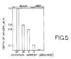
- Fig 5 is a chart showing the effect of oxidation time in air on depth of oxide coating.
- To demonstrate the effects obtained by various processing steps used in the method of the present invention, four mild steel test panels (low carbon (0.10%) steel to British Standard BS970 045 M10)approximately 25mm square and 0.55 mm thick were heat treated for two hours at 570°C in an atmosphere of 50% ammonia and 50% endothermic gas mixture (carbon monoxide, carbon dioxide, nitrogen and hydrogen). After heat treatment, the four test panels were cooled in different ways.
- Sample 1 was taken straight from the heat treatment zone and, whilst in the same heat treatment atmosphere, was immediately quenched in a water-free quenching oil sold by British Petroleum under the designation QUENDILLA WA 22. This operation was effected in a sealed quench furnace.
-
Sample 2 was removed from the furnace, exposed to air at 20°C for 5 seconds and then quenched in an oil-in-water emulsion produced by mixing a soluble oil sold under the Trade Mark EVOCQUENCH GW with water in an oil:water volume ratio of 1:5.5. - Sample 3 was cooled by removing it from the heat treatment furnace, exposing it to air at 20°C for 1 second and then quenching it into an oil-in-water emulsion produced by mixing a soluble oil sold under the Trade Mark ILOTEMP 4 at an oil:water volume ratio of 1:10.
- Sample 4 was removed from the furnace and merely allowed to cool completely in air at 20°C.
- After cooling the samples were analysed as described below and the results obtained given in Tables 1 to 6 below.
- The oil quenched samples were first vapour degreased and then all the test pieces were introduced into an Auger Electron Spectrometer which was evacuated down to a pressure of 1 x 10⁻⁸ torr and allowed to remain under this reduced pressure overnight to remove any gases which had been absorbed into the surface of the samples.
- All four samples were then analyzed for the existence of all elements except hydrogen and helium and measured to the nearest 0.1 atomic percent of a mono layer. In the Auger Electron Spectrometer, the background vacuum was 1 x 10⁻⁸ torr, the electron beam energy was 1 - 3 KeV, the beam current was 1 microampere and the energy range was 20 - 1700 eV. A layer-by-layer analysis was conducted by using the Auger Electron Spectrometer in conjunction with sequential ion beam sputtering to remove the layers. In the ion beam sputtering technique, argon ions were used at an energy of 3 keV and a current density of 75 and 150 microampere.cm² under a gas pressure of 5 x 10⁻⁵ torr. The results of such analyses are given in Tables 1 to 4 below. Additionally, samples 1 and 3, in areas remote from the ion beam sputter damage, were then subjected to ball cratering using a 30mm diameter steel ball and a 1 miro-metre diamond paste as the polising medium. The Auger Electron Spectrometer was then used to make line scans across the crater diameters and the elemental composition on these lines was measured at a number of depths between 2 x 10⁻⁶ metres and 22 x 10⁻⁶ metres.
- The elemental compositions were initially read in atomic percentages and were then calculated as weight percentages and displayed in the Tables below.
- The percentages by weight of all detectable elements present in amounts greater than 0.1% were recorded.
TABLE 1 Sample 1. Composition (wt%) Element Fe C N O S Cl Ca Depth (10⁻⁹m) 0 42.3 29.3 5.2 13.9 3.6 4.7 1.1 16 85.7 1.5 10.1 1.0 1.0 0.2 0.5 140 89.4 0.8 9.1 0.4 0.2 0 0 300 90.0 0.9 8.4 0.5 0.2 0 0 350 91.0 0.8 7.6 0.4 0.2 0 0 TABLE 2 Sample 2Composition (wt%) Element Fe C N O S Cl K Na Depth (10⁻⁹m) 0 38.6 23.9 1.0 21.1 5.4 0.9 2.0 7.0 16 72.6 1.0 0 25.3 0.5 0 0.6 0 140 75.0 0.5 0 24.5 0 0 0 0 300 76.2 0.3 0 23.4 0 0 0 0 TABLE 3 Sample 3 Composition (wt%) Element Fe C N O S Cl Depth (10⁻⁹m) 0 57.0 8.9 0 31.6 0.7 1.8 16 72.7 0.3 0 27.0 0 0 140 74.8 0.2 0.7 24.3 0 0 300 82.7 0.3 5.1 12.0 0 0 430 83.8 0.3 6.2 9.8 0 0 620 85.6 0.3 7.4 6.6 0 0 TABLE 4 Sample 4 Composition (wt%) Element Fe C N O S Cl K Na Depth (10⁻⁹m) 0 46.7 5.0 1.1 32.9 0.8 8.7 3.6. 1.1 16 70.5 0.3 0 28.8 0 0 0.4 0 140 73.0 0.1 0 26.8 0 0 0 0 300 73.1 0 0 26.9 0 0 0 0 TABLE 5 Sample 1 (Ball Crater) Composition (wt%) Element Fe C N 0 Depth 10-⁶m) 3.9 90.2 0.6 8.9 0.3 7.4 91.2 0.5 8.1 0.19 10.7 91.4 0.3 8.1 0.3 15.0 91.9 0.4 7.6 0.16 21.7 92.0 0.5 7.4 0.16 TABLE 6 Sample 3 (Ball Crater) Composition (wt%) Element Fe C N 0 Depth (10.-6m) 2.3 86.8 0.4 7.4 5.5 4.2 91.0 0.3 8.4 0.4 6.2 91.1 0.4 8.2 0.3 9.5 91.6 0.4 7.9 0.2 11.2 91.5 0.5 7.9 0.2 - Additionally, a more detailed measurement of the variations in the elemental composition of the layers was carried out on a new area of sample 3 in the first few microns. The results obtained are shown in Table 7 below:
TABLE 7 Sample 3 Composition (wt%) Element Fe C N O S Depth (10⁻⁶m) 0.3 83.0 0.4 5.0 11.4 0.2 0.4 84.1 0.5 5.2 10.3 0 0.6 85.0 0.3 5.7 9.0 0 0.9 86.4 0.3 6.3 7.0 0 1.3 85.9 0.3 6.9 6.9 0 1.6 86.3 0.14 6.6 6.9 0 2.3 87.3 0.2 5.8 6.6 0 2.9 88.9 0.2 6.0 4.9 0 3.9 90.6 0.4 6.1 2.9 0 4.9 92.1 0 6.6 1.3 0 - When considering the above Tables, it is to be appreciated that the heat treatment process to which the samples were subjected is one which produces an epsilon iron carbonitride layer to a depth well in excess of 20 micrometres. The epsilon iron carbonitride layer consists of a porous and a non-porous region, the porous region extending from the surface of the sample downwardly to a depth of about 10 micrometres, and the non-porous region underlying this At a depth of 20 micrometres, the epsilon iron carbonitride layer has a typical elemental composition of 92% by weight of iron, 7.4% by weight of nitrogen, 0.4% by weight of carbon and 0.2% by weight of oxygen.
- In the case of Sample 1, the elemental composition for the whole layer is consistent with the epsilon iron carbonitride region of the ternary iron-carbon-nitrogen system defined by Naumann and Langescheid (Eisenhüttenwesen 1965, 36,677). The layer of Sample 1 is also consistent with the idealized iron nitride formula Fe₂N1-x where x is 0 to 1, for the epsilon phase reported by Lightfoot and Jack in "Kinetics of Nitriding With and Without White Layer Formation" (Proceedings of Heat Treatment Conference 1973 organised by Heat Treatment and Joint Committee of the Iron and Steel Institute), the nitrogen content being between 7.5 and 11% by weight.
- In order to present the information more clearly, reference is drawn to attached Figures 1 to 4 which are graphs plotting the iron and nitrogen, iron and oxygen, or iron, oxygen and nitrogen contents in a layer region of Samples 1 to 4 respectively. The layer region chosen is one which extends from 16 x 10⁻⁹ metres to about 400 x 10⁻⁹ metres from the surface. The first measurement plotted on the graph is that at 16 x 10⁻⁹ metres, the samples having been subjected to an initial ion sputtering technique to remove foreign contaminants from the outer surface.
- As can be seen from the above Tables and Figures, oxidation of the Samples after heat treatment either solely in air or initially in air and followed by quenching in the oil/water emulsion results in displacement of nitrogen by oxygen. Displacement of nitrogen is total in the outermost surface layers portions (i.e. down to a depth which may vary between 0.1 micrometre and 1 micrometre,) depending upon the time of exposure to air while the sample is hot before quenching, and also on the cooling rate in the quench. Partial displacement of the nitrogen continues in some instances to depths in excess of 1 micrometre.
-
Samples 2 and 3 were corrosion resistant becauseof the predominance of iron oxide mainly in the form of Fe₃0₄ to depth of at least 0.1 micrometre and sometimes down to more than 1 micrometre in depth. - In Sample 4, the iron to oxygen ratio at the extreme surface indicates a composition approaching that of Fe₂0₃ but as the depth increases into the layer, the composition becomes progressively closer to that of Fe₃0₄.
- In
Samples 2 and 3, the iron to oxygen ratio suggests a structure close to Fe₃0₄ in the outer surface layer portions but increasing in Fe0 on progression inwards. - It will be appreciated from comparison of Tables 2 and 3 and Figs 2 and 3 that the control of the time in air at the pre-quench temperature and also the cooling speed in the quench medium is extremely critical with respect to displacement of nitrogen from the outer surface layer portions.
- Lastly, it will be apparent from an examination of the Tables and Figures that the oxygen actually displaces nitrogen from the lattice, in some cases totally and in other cases to a lesser extent but still to an extent of about 90% removal down to a depth of about 0.15 micrometre This is in direct contrast to the reported effects obained by salt bath oxidation following salt bath nitriding where oxygen is reported as being simply absorbed into the nitride lattice.
- With reference to Fig. 5, the first four blocks relate to exposure of nitrocarburised component at above 550°C to air for the specified time, followed by quenching in a water/oil emulsion. The last block relates to quenching of a nitrocarburized component directly into oil without exposure to air.
- Steel components according to the present invention have a corrosion resistance which is superior even to components surface treated to produce an epsilon iron nitride surface layer, oil quenched, degreased (or slow cooled under a protective atmosphere) and then dipped in a de-watering oil so that the de-watering oil is absorbed into an absorbent outer portion of the epsilon iron nitride surface layer. Table 8 below compares the corrosion resistant properties of various types of steel component:-
TABLE 8 SAMPLE NO SALT SPRAY RESISTANCE (HOURS) 1 0 2 17 3 96 4 150+ - The salt spray resistance was evaluated in a salt spray test in accordance with ATSM Standard B117-64 in which the component is exposed in a salt spray chamber maintained at 95+2-3°F to a salt spray prepared by dissolving 5+/- 1 parts by weight of salt in 95 parts of distilled water and adjusting the pH of the solution such that, when atomised at 95°F, the collect solution has a pH in range of 6.5 to 7.2 After removal from the salt spray test, the components are washed under running water, dried and the incidence of red rusting is assessed. Components exhibiting any red rusting are deemed to have failed.
- In the above Table 8, the samples are identified as follows:-
Sample 1 = a plain, ie untreated steel component.
Sample 2 = a steel component having an epsilon iron nitride surface layer produced by the first-mentioned heat treating step in the method of the invention, followed by oil quenching and degreasing (or slow cooling under a protective atmosphere).
Sample 3 = the steel component ofSample 2 additionally dipped in a de-watering oil.
Sample 4 = the steel component having an epsilon iron nitride layer and an oxide-rich surface layer produced in accordance with the present invention after lapping the surface to a finish of 0.2 micrometres.
It is to be noted that, in the case of Sample 4, the actual salt spray resistance figure depends upon the surface finish. In a particular example, the steel component treated is a shock absorber Piston rod with a final surface finish of 0.13 to 0.15 micrometres Ra. Such a component was found to have a salt spray resistance of 250 hours.
The improvement in fatigue properties will become apparent from an examination of Table 9 below:-TABLE 9 SAMPLE ENDURANCE LIMIT AT 10⁷ Cycles N/mm² Plain Notched 5 250 190 6 440 350 7 260 195 8 435 345
The fatigue property was evaluated using an NPL-type two point loading rotary beam machine employing standard 0.30" (7.6mm) diameter NPL test pieces.
In Table 9 above:-
Sample 5 = an untreated steel component.
Sample 6 = a steel component which has an epsilon iron nitride surface layer formed thereon by heat treatment at 570°C for about 2 hours in an atmosphere of 50% ammonia and 50% endothermic gas mixture, followed by oil quenching.
Sample 7 = a steel component having an epsilon iron nitride layer produced as inSample 6 above, and subsequently oxidised in a sodium/potassium hydroxide/sodium nitrate salt bath mixture (sold as "Degussa ABl salt") at a temperature of 400°C as recommended by the suppliers of the salt mixture.
Sample 8 = a steel component having an epsilon iron nitride surface layer formed by heat treatment as inSample 6 but subsequently oxidised in steam at 540°C for 30 minutes, followed by oil quenching. - It will be seen that oxidation using the salt bath treatment as per Sample 7 above reduces the fatigue properties almost back to the level of Sample 5. This is caused by nitrogen being precipitated from solid solution. The gaseous oxidation technique as per Sample 8 can be applied over a much wider temperature range. Consequently by using a controlled oxidation process at 550°C followed by oil quenching, the improved fatigue properties associated with the heat treatment process as per
Sample 6 are maintained. - This occurs because at the higher temperature, most of the nitrogen remains in solid solution and is maintained therein by the subsequent oil quenching.
- A specific example of the present invention will now be described:-
A shock absorber piston rod having a length of 230mm, a diameter of 12.5 mm, and an initial surface roughness of 0.13 to 0.15 micrometres Ra was manufactured by machining a bar of low carbon steel (BS970-045M10) and was heat treated for two hours at 570°C in an atmosphere of 50% ammonia and 50% endothermic gas mixture (Carbon monoxide, carbon dioxide, nitrogen and hydrogen). The rod was then cooled slowly under the protection of the same atmosphere as used in the above mentioned heat treatment. The resultant rod had a 20 micrometre thick layer of epsilon iron nitride thereon and a surface roughness of 0.64 micrometres Ra. - In view of the high surface finish requirements for the piston rod, it was lapped at this stage to a surface roughness of 0.13 micrometres Ra.
- Following this, the rod was oxidised in an exothermic gas mixture containing its moisture of combustion for 10 minutes at 400°C to produce a 0.5 micrometre thick oxide-rich surface layer. The piston rod was then cooled by water quenching.
- The piston rod was found to have a salt spray resistance of 250 hours according to the above described salt spray test.
- In a modification of the above described specific example, the rod was oxidised for 15 minutes at 400°C in the exothermic gas mixture, but during the last 5 minutes of the 15 minute cycle, sulphur dioxide was introduced into the furnace in an amount such as to give a concentration of 0.25% by volume in the furnace atmosphere. Such a technique caused about 1% of the iron oxide (Fe₂0₃) on the surface of the rod to be converted to iron sulphide which gave an aesthetically pleasing shiny black surface to the rod.
- The technique of sulphiding is not restricted to components in the form of damper rods and can be used in respect of any components on which it is desirable to have a black hard-wearing surface. With surface finishes greater than 0.25 micrometres Ra, it will be necessary to wax coat in order to produce the desired corrosion resistance. To effect sulphiding, the S0₂ content in the oxidizing furnace may be up to 1% by volume and the temperature may be in the range of 300°C to 600°C. The S0₂ will normally be added to the furnace at some stage after the oxidizing heat treatment has started in order to convert some of the already formed iron oxide to iron sulphide.
- The invention is particularly applicable to non-alloy steels having a low carbon content, for example up to 0.5% carbon.
Claims (9)
- A method of manufacturing a manufacturing a corrosion resistant non-alloy steel component comprising the steps of heat treating a non-alloy steel component in a nitriding gaseous atmosphere to produce an epsilon iron nitride or iron carbonitride surface layer thereon; and subsequently oxidising the component to provide an oxide-rich surface layer, characterized in that between the heat treating and oxidising steps the component is cooled and mechanically surface finished.
- A method as claimed in Claim 1, wherein the mechanical surface finishing is effected so that the surface roughness of the component does not exceed 0.2 micrometres Ra.
- A method as claimed in Claim 1 or 2, wherein the oxidising is effected by heat treating the surface finished component in a gaseous atmosphere at 300 to 600°C.
- A method as claimed in Claim 3, wherein the component is a piston rod.
- A method as claimed in Claim 4, wherein the oxidising is effected by heat treating the component in an exothermic gas mixture containing its moisture of combustion.
- A method as claimed in Claim 5, wherein the oxide-rich surface layer is 0.5 micrometre thick and is Fe₃O₄.
- A method as claimed in Claim 4, wherein the surface finishing step is effected so that the component after the oxidising step has a final surface finish of 0.13 to 0.15 micrometre Ra.
- A method as claimed in any one of Claims 1 to 7, wherein the heat treatment in the nitriding gaseous atmosphere is effected at a temperature of 550 to 720°C.
- A method as claimed in any one of Claims 1 to 7, wherein a sulphur-containing compound is introduced into the oxidising atmosphere to produce iron sulphide whereby the surface of the component contains iron sulphide as well as iron oxide.
Applications Claiming Priority (9)
| Application Number | Priority Date | Filing Date | Title |
|---|---|---|---|
| GB8131133 | 1981-10-15 | ||
| GB8138318 | 1981-12-18 | ||
| GB8205999 | 1982-02-26 | ||
| GB8131133 | 1982-07-15 | ||
| GB8220495 | 1982-07-15 | ||
| GB8220495 | 1982-07-15 | ||
| GB8205999 | 1982-07-15 | ||
| GB8138318 | 1982-07-15 | ||
| EP82305400A EP0077627B1 (en) | 1981-10-15 | 1982-10-11 | Corrosion resistant steel components and method of manufacture |
Related Parent Applications (1)
| Application Number | Title | Priority Date | Filing Date |
|---|---|---|---|
| EP82305400.2 Division | 1982-10-11 |
Publications (3)
| Publication Number | Publication Date |
|---|---|
| EP0229325A2 EP0229325A2 (en) | 1987-07-22 |
| EP0229325A3 EP0229325A3 (en) | 1988-09-21 |
| EP0229325B1 true EP0229325B1 (en) | 1995-01-04 |
Family
ID=27513236
Family Applications (1)
| Application Number | Title | Priority Date | Filing Date |
|---|---|---|---|
| EP86117233A Expired - Lifetime EP0229325B1 (en) | 1981-10-15 | 1982-10-11 | Method of manufacturing a corrosion resistant steel component |
Country Status (1)
| Country | Link |
|---|---|
| EP (1) | EP0229325B1 (en) |
Cited By (1)
| Publication number | Priority date | Publication date | Assignee | Title |
|---|---|---|---|---|
| DE102004025865A1 (en) * | 2004-05-27 | 2005-12-22 | Volkswagen Ag | Manufacturing piston rod for vehicle suspension shock absorber, provides unhardened rod with nitrided layer using proprietary plasma process |
Families Citing this family (10)
| Publication number | Priority date | Publication date | Assignee | Title |
|---|---|---|---|---|
| DE19510302C2 (en) * | 1995-03-22 | 1997-04-24 | Bilstein August Gmbh Co Kg | Surface-treated piston rod and process for its manufacture |
| CN1217438A (en) * | 1997-11-07 | 1999-05-26 | 张昕辉 | Metal-based lubricating and wear-resistant functionally graded materials |
| DE10062431A1 (en) * | 2000-12-18 | 2002-06-20 | Continental Teves Ag & Co Ohg | Hydraulic piston and method for its surface treatment |
| GB2383800A (en) * | 2001-07-25 | 2003-07-09 | Nsk Europ Technology Co Ltd | Performance enhancement of steel auxiliary bearing components |
| US7520940B2 (en) | 2004-07-29 | 2009-04-21 | Caterpillar Inc. | Steam oxidation of powder metal parts |
| JP4762077B2 (en) * | 2006-08-09 | 2011-08-31 | 日本パーカライジング株式会社 | Hardening method of steel member, hardened steel member and hardened surface protective agent |
| RU2390582C2 (en) * | 2008-07-28 | 2010-05-27 | Государственное образовательное учреждение высшего профессионального образования "Оренбургский государственный университет" | Procedure for chemical-thermal treatment of steel items |
| DE102008047724A1 (en) * | 2008-09-18 | 2010-03-25 | Schaeffler Kg | Sliding disc in a sprag clutch |
| IN2015MN00144A (en) * | 2012-06-26 | 2015-10-16 | Fulvio Fabrizio Cavina | |
| EP4008802A1 (en) * | 2020-12-02 | 2022-06-08 | Linde GmbH | Method of and apparatus for oxidative post-processing of a nitrided or nitrocarburized article |
Family Cites Families (7)
| Publication number | Priority date | Publication date | Assignee | Title |
|---|---|---|---|---|
| US2343418A (en) * | 1941-01-02 | 1944-03-07 | Aviat Corp | Method of making propeller blades |
| GB693715A (en) * | 1950-02-06 | 1953-07-08 | Autoyre Company | Process for finishing steel articles |
| FR1157201A (en) * | 1956-08-08 | 1958-05-28 | Renault | Surface hardening process for hardened and hardened parts |
| DE1179969B (en) * | 1956-10-22 | 1964-10-22 | Lasalle Steel Co | Process for the heat treatment and deformation of steel |
| DD119822A1 (en) * | 1975-06-20 | 1976-05-12 | ||
| JPS52138027A (en) * | 1976-04-08 | 1977-11-17 | Nissan Motor | Ferrous member superior in initial fitting and wear resisting property and production process therefor |
| EP0061272A1 (en) * | 1981-03-23 | 1982-09-29 | LUCAS INDUSTRIES public limited company | Electric motor |
-
1982
- 1982-10-11 EP EP86117233A patent/EP0229325B1/en not_active Expired - Lifetime
Non-Patent Citations (3)
| Title |
|---|
| DURFERRIT-HANDBUCH, 1977, pages 69 - 71 |
| G. WAHL, HÄRTEREI-KOLLOQUIUM, 7 October 1981 (1981-10-07), Wiesbaden |
| J. MÜLLER ET AL., HÄRTEREI-KOLLOQUIUM, 1980, Wien |
Cited By (1)
| Publication number | Priority date | Publication date | Assignee | Title |
|---|---|---|---|---|
| DE102004025865A1 (en) * | 2004-05-27 | 2005-12-22 | Volkswagen Ag | Manufacturing piston rod for vehicle suspension shock absorber, provides unhardened rod with nitrided layer using proprietary plasma process |
Also Published As
| Publication number | Publication date |
|---|---|
| EP0229325A2 (en) | 1987-07-22 |
| EP0229325A3 (en) | 1988-09-21 |
Similar Documents
| Publication | Publication Date | Title |
|---|---|---|
| US4496401A (en) | Corrosion resistant steel components and method of manufacture thereof | |
| EP0217420B1 (en) | Corrosion resistant steel components and method of manufacture thereof | |
| US3885995A (en) | Process for carburizing high alloy steels | |
| EP0229325A2 (en) | Method of manufacturing a corrosion resistant steel component | |
| US3748195A (en) | Method for forming a soft nitride layer in a metal surface | |
| DE69202114T2 (en) | Treatment processes for iron materials to improve their corrosion resistance and wear properties at the same time. | |
| Flis et al. | Corrosion behaviour of stainless steels aner plasma and ammonia nitriding | |
| US5228929A (en) | Thermochemical treatment of machinery components for improved corrosion resistance | |
| Zakroczymski et al. | The effect of plasma nitriding-base treatments on the absorption of hydrogen by iron | |
| JP3388510B2 (en) | Corrosion-resistant and wear-resistant steel and its manufacturing method | |
| US5213638A (en) | Surface modified copper alloys | |
| US3988515A (en) | Case-hardening method for carbon steel | |
| JPH0146586B2 (en) | ||
| RU1836484C (en) | Method of application of nitride layers on parts made of titanium and titanium alloys | |
| US5320689A (en) | Surface modified copper alloys | |
| Mordike | Laser gas alloying | |
| JP3695643B2 (en) | Iron parts | |
| EP0931849B1 (en) | Process suitable to give a direct protection against the wear corrosion of metallic pieces | |
| JPH0776766A (en) | Method for improving wear resistance and corrosion resistance of ferrous metal parts | |
| JPH06184728A (en) | Surface treatment method for steel | |
| CA2163917A1 (en) | Method for the pre-treatment of steel parts prior to salt bath nitriding | |
| Nair et al. | X-ray photoelectron spectroscopy studies of hard coatings formed by titanium implantation on 304 stainless steel | |
| WO1991000367A1 (en) | Carburising treatment of a steel with reduction of the hydrogen content in the carburized layer | |
| Goel et al. | Surface Modification of Austenitic 304 Stainless Steel by N and 11 Ion Implantation | |
| Saif et al. | Improvement of the Thermal Fatigue Lifetime of Plasma Sprayed Coatings by Laser Treatment |
Legal Events
| Date | Code | Title | Description |
|---|---|---|---|
| PUAI | Public reference made under article 153(3) epc to a published international application that has entered the european phase |
Free format text: ORIGINAL CODE: 0009012 |
|
| 17P | Request for examination filed |
Effective date: 19861219 |
|
| AC | Divisional application: reference to earlier application |
Ref document number: 77627 Country of ref document: EP |
|
| AK | Designated contracting states |
Kind code of ref document: A2 Designated state(s): DE FR GB IT SE |
|
| PUAL | Search report despatched |
Free format text: ORIGINAL CODE: 0009013 |
|
| AK | Designated contracting states |
Kind code of ref document: A3 Designated state(s): DE FR GB IT SE |
|
| 17Q | First examination report despatched |
Effective date: 19931122 |
|
| GRAA | (expected) grant |
Free format text: ORIGINAL CODE: 0009210 |
|
| AC | Divisional application: reference to earlier application |
Ref document number: 77627 Country of ref document: EP |
|
| AK | Designated contracting states |
Kind code of ref document: B1 Designated state(s): DE FR GB IT SE |
|
| ITF | It: translation for a ep patent filed | ||
| REF | Corresponds to: |
Ref document number: 3280464 Country of ref document: DE Date of ref document: 19950216 |
|
| ET | Fr: translation filed | ||
| PLBI | Opposition filed |
Free format text: ORIGINAL CODE: 0009260 |
|
| 26 | Opposition filed |
Opponent name: DEGUSSA AG, FRANKFURT - ZWEIGNIEDERLASSUNG WOLFGAN Effective date: 19950929 |
|
| PLBF | Reply of patent proprietor to notice(s) of opposition |
Free format text: ORIGINAL CODE: EPIDOS OBSO |
|
| PLBO | Opposition rejected |
Free format text: ORIGINAL CODE: EPIDOS REJO |
|
| PLBN | Opposition rejected |
Free format text: ORIGINAL CODE: 0009273 |
|
| STAA | Information on the status of an ep patent application or granted ep patent |
Free format text: STATUS: OPPOSITION REJECTED |
|
| 27O | Opposition rejected |
Effective date: 19970623 |
|
| REG | Reference to a national code |
Ref country code: GB Ref legal event code: 732E |
|
| REG | Reference to a national code |
Ref country code: FR Ref legal event code: TP |
|
| REG | Reference to a national code |
Ref country code: FR Ref legal event code: CL |
|
| PGFP | Annual fee paid to national office [announced via postgrant information from national office to epo] |
Ref country code: SE Payment date: 20011005 Year of fee payment: 20 |
|
| PGFP | Annual fee paid to national office [announced via postgrant information from national office to epo] |
Ref country code: GB Payment date: 20011010 Year of fee payment: 20 Ref country code: FR Payment date: 20011010 Year of fee payment: 20 |
|
| PGFP | Annual fee paid to national office [announced via postgrant information from national office to epo] |
Ref country code: DE Payment date: 20011029 Year of fee payment: 20 |
|
| REG | Reference to a national code |
Ref country code: GB Ref legal event code: IF02 |
|
| PG25 | Lapsed in a contracting state [announced via postgrant information from national office to epo] |
Ref country code: GB Free format text: LAPSE BECAUSE OF EXPIRATION OF PROTECTION Effective date: 20021010 |
|
| REG | Reference to a national code |
Ref country code: GB Ref legal event code: PE20 Effective date: 20021010 |
|
| EUG | Se: european patent has lapsed |
Ref document number: 86117233.6 |