EP0228932B1 - Apparatus for use in the seismic exploration of the sea for the receipt of seismic signals and their transmission to a central control and recording system - Google Patents
Apparatus for use in the seismic exploration of the sea for the receipt of seismic signals and their transmission to a central control and recording system Download PDFInfo
- Publication number
- EP0228932B1 EP0228932B1 EP86402589A EP86402589A EP0228932B1 EP 0228932 B1 EP0228932 B1 EP 0228932B1 EP 86402589 A EP86402589 A EP 86402589A EP 86402589 A EP86402589 A EP 86402589A EP 0228932 B1 EP0228932 B1 EP 0228932B1
- Authority
- EP
- European Patent Office
- Prior art keywords
- signals
- seismic
- data acquisition
- switch
- line
- Prior art date
- Legal status (The legal status is an assumption and is not a legal conclusion. Google has not performed a legal analysis and makes no representation as to the accuracy of the status listed.)
- Expired
Links
Images

Classifications
-
- G—PHYSICS
- G01—MEASURING; TESTING
- G01V—GEOPHYSICS; GRAVITATIONAL MEASUREMENTS; DETECTING MASSES OR OBJECTS; TAGS
- G01V1/00—Seismology; Seismic or acoustic prospecting or detecting
- G01V1/22—Transmitting seismic signals to recording or processing apparatus
Definitions
- the invention relates to a device for receiving seismic signals and transmitting them to a central control and recording system.
- the invention relates to a reception and transmission device where the signals received by a plurality of sensors distributed inside the successive elements of a seismic flute of great length, are grouped together before their transmission in apparatuses of acquisition.
- the signals received by each of the acquisition devices during the same transmission-reception cycle are sampled, digitized and recorded.
- the various acquisition devices transmit, one after the other and sequentially, the data they have collected on one or more common transmission channels.
- the electronic acquisition devices are arranged for example in rigid cases interposed between the elements of the seismic streamer. Such a device is described for example in French patent 2,471,088.
- the increase in the total number of receivers makes it possible both to reduce the intertrace, that is to say the interval between two successive locations of the seismic profile studied, restored by two adjacent recording traces and also, by combination and processing of the recorded signals, to increase the smoothness of restitution of the recordings.
- the device according to the invention makes it possible to avoid the above-mentioned drawbacks.
- It comprises a series of interconnected sections each provided with a plurality of seismic receivers distributed over its length, acquisition devices arranged in at least part of the interposed boxes, for digitizing and memorizing each of the signals coming from at least a group of seismic receivers to which it is connected by connection means and digital transmission means for the transfer to the acquisition devices, of interrogation signals coming from a central control and recording device and the transfer to it signals transmitted sequentially by the acquisition devices in response to the interrogation signals.
- connection means connecting each group of receivers to the associated acquisition device comprising a single transmission line, switches for connecting the outputs of the various electronic modules on the transmission line and synchronization means comprising a clock element arranged in each acquisition device, a common connection line connecting each clock element to control elements arranged in the various electronic modules, said control elements being interconnected with one another so as to generate control signals in sequence, the duration is equal to the repetition period of the clock, which control signals are applied respectively to the different switches urs.
- the acquisition devices retain only the functions of digitization, storage and multiplexed transmission.
- the dispersion of the electronic modules inside the flute sections, in the vicinity of the receivers, makes it possible to obtain a better distribution of the masses and consequently a better balance in the water, which reduces the parasitic noises of flow.
- the seismic flute shown diagrammatically in FIG. 1 comprises a flexible sheath 1 made up of a series of elements Fi, F 2 ... F i ... F m each containing a set of seismic receivers, these elements being connected to each other others by connection boxes Gi, G 2 ... G; ... G m containing signal acquisition devices.
- the seismic streamer is towed in immersion by a ship 2 comprising a central control and recording system.
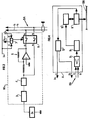
- the flute element Fi shown diagrammatically in FIG. 2 comprises a set of seismic receivers Si, S 2 ... S k-1 , S k , S k + 1 ... S n distributed at regular intervals over its entire length and associated respectively with electronic modules M 1 , M 2 ... M k -i, M k , M k +1 ... Mn.
- Each of them has (Fig. 3) a low-pass anti-aliasing filter 3 and a low-cut filter 4 interconnected in series.
- the signals delivered by the associated receiver S k are applied to filters 3 and 4.
- the output of filter 4 is connected to the input of an inverting amplifier 5.
- the outputs of the filter 4 and of the amplifier 5 are applied to the inputs e 1 , e 2 of a two-way electronic switch 6.
- the outputs vi, v 2 of the switch 6 are respectively connected to two conductive wires l 1 and 1 2 of a shielded two-wire line constituting an analog bus B A.
- the control input e c of the electronic switch 6 is connected to a first output of a bistable rocker 7.
- a first input of this is connected to a line I H running all along the flute section F k which conveys a clock signal H.
- a second input of the bistable rocker 7 is connected to a line section C k coming from the previous electronic module M k - 1 .
- the complementary output of the rocker 7 is connected to the second input of the identical rocker contained in the following electronic module M k + 1 .
- the analog bus B A (Fig. 2) is connected, at one end of the flute element Fi, to an acquisition device Aj.
- variable gain amplifier 8 Fig. 4
- Such a variable gain seismic amplifier is described in French patents 2,469,040 or 2,487,603.
- the amplified signals coming from the amplifier 8 are digitized in an analog-digital converter 9 then stored in a storage device 10.
- the acquisition apparatus Ai also includes a decoding and switching assembly 11 adapted to decode the address and control signals circulating on the digital bus B N.
- the assembly 11 connects the storage member 10 to the cable B N so that the digital signals which have been collected are transferred to the central recording system on the ship.
- the decoding and switching assembly is also suitable for detecting and reconstructing synchronization signals originating from the central system via the digital bus B N.
- synchronization signals are applied to a clock element 12 adapted to create the clock signal H and to transfer it to the line I H (Fig. 2), as well as a signal D of the same frequency as the clock signal. H and offset with respect thereto, this signal D being transmitted on the line section Ci towards the first module Mi.
- the device operates as follows: The seismic signals picked up by the receivers Si to S n of each flute element, in response to the waves emitted by a seismic source towed by the ship and returned by the discontinuities of the subsoil, are amplified and filtered in the associated electronic modules (Mi-Mn).
- the signal is transferred to the associated acquisition device until the arrival by line L H of a clock pulse H.
- the retriggering of the rocker 7 which results therefrom, opens the switch 6 and creates a pulse which is transmitted by the line section C 2 to the rocker 7 of the following electronic module M 2 .
- all the electronic modules in turn connect to the analog bus B A and transfer a sample of the signal picked up by the associated receivers.
- All the rockers 7 of the different modules constitute a shift register with distributed elements.
- the application of a new pulse D on the line section C 1 triggers a new sequence of transfer of a sample successively from all the electronic modules to the associated acquisition device.
- each of the acquisition devices connects on command to the digital bus B N and transfers to the central system on board the ship all the sampled signals that it has memorized.
Description
L'invention a pour objet un dispositif pour recevoir des signaux sismiques et les transmettre à un système central de commande et d'enregistrement.The invention relates to a device for receiving seismic signals and transmitting them to a central control and recording system.
Plus particulièrement, l'invention concerne un dispositif de réception et de transmission où les signaux reçus par une pluralité de capteurs répartis à l'intérieur des éléments successifs d'une flûte sismique de grande longueur, sont regroupés préalablement à leur transmission dans des appareils d'acquisition électroniques.More particularly, the invention relates to a reception and transmission device where the signals received by a plurality of sensors distributed inside the successive elements of a seismic flute of great length, are grouped together before their transmission in apparatuses of acquisition.
Les signaux reçus par chacun des appareils d'acquisition durant un même cycle d'émission-réception, sont échantillonnés, numérisés et enregistrès.The signals received by each of the acquisition devices during the same transmission-reception cycle are sampled, digitized and recorded.
A l'issue de chaque cycle et sur commande du système central, les différents appareils d'acquisition transmettent l'un après l'autre et séquentiellement les données qu'ils ont collectées sur une ou plusieurs voies de transmission commune(s).At the end of each cycle and on command from the central system, the various acquisition devices transmit, one after the other and sequentially, the data they have collected on one or more common transmission channels.
Les appareils électroniques d'acquisition sont disposés par exemple dans des boitiers rigides intercalés entre les éléments de la flûte sismique. Un tel dispositif est décrit par exemple dans le brevet français 2.471.088.The electronic acquisition devices are arranged for example in rigid cases interposed between the elements of the seismic streamer. Such a device is described for example in French patent 2,471,088.
La tendance actuelle dans le domaine de la géophysique est à l'allongement des flûtes sismiques.The current trend in the field of geophysics is to lengthen the seismic streamers.
L'accroissement du nombre total de récepteurs permet à la fois de réduire l'intertrace, c'est-à-dire l'intervalle entre deux emplacements successifs du profil sismique étudié, restitués par deux traces d'enregistrement adjacentes et aussi, par combinaison et traitement des signaux enregistrès, d'accroître la finesse de restitution des enregistrements.The increase in the total number of receivers makes it possible both to reduce the intertrace, that is to say the interval between two successive locations of the seismic profile studied, restored by two adjacent recording traces and also, by combination and processing of the recorded signals, to increase the smoothness of restitution of the recordings.
Le nombre d'appareils électroniques intercalés et la densité d'intégration de composants qui y sont contenus, augmente.The number of electronic devices inserted and the density of integration of components contained therein is increasing.
L'alourdissement des boitiers qui en résulte présente de nombreux inconvénients particulièrement en prospection sismique marine où les flûtes sont constituées d'une pluralité d'éléments remplis d'un liquide de densité inférieure à celle de l'eau, qui leur assure une certaine flottabilité.The weighting of the boxes which results has many disadvantages, particularly in marine seismic prospecting where the flutes consist of a plurality of elements filled with a liquid of density lower than that of water, which ensures them a certain buoyancy. .
La présence de boitiers relativement lourds entre les éléments rend encore plus inégale la répartition des masses, ce qui a pour effet d'accroître la trai- née et par conséquent les bruits parasites d'écoulement qui viennent se superposer aux signaux utiles.The presence of relatively heavy boxes between the elements makes the distribution of masses even more unequal, which has the effect of increasing the drag and consequently the parasitic flow noises which are superimposed on the useful signals.
La longueur des liaisons entre capteurs et appareils d'acquisition qui peut atteindre pour certains plusieurs dizaines de mètres, augmente considérablement leur sensibilité aux signaux parasites. Ceci est particulièrement vrai dans le cas où l'on utilise dans les flûtes des récepteurs acoustiques autres que des capteurs à céramiques et en particulier des hydrophones de grande longueur et de structure continue, dont la capacité est plus faible, à sensibilité égale.The length of the links between sensors and acquisition devices which can reach for several tens of meters, considerably increases their sensitivity to parasitic signals. This is particularly true in the case where acoustic receivers other than ceramic sensors are used in the flutes and in particular hydrophones of great length and of continuous structure, the capacity of which is lower, with equal sensitivity.
Le dispositif selon l'invention permet d'éviter les inconvénients ci-dessus mentionnés.The device according to the invention makes it possible to avoid the above-mentioned drawbacks.
Il comporte une série de sections interconnectées pourvues chacune d'une pluralité de récepteurs sismiques répartis sur sa longueur, des appareils d'acquisition disposés dans au moins une partie des boîtiers intercalés, pour numériser et mémoriser chacun des signaux provenant d'au moins d'un groupe de récepteurs sismiques auquel il est connecté par des moyens de connexion et des moyens de transmission numériques pour le transfert vers les appareils d'acquisition, de signaux d'interrogation provenant d'un dispositif central de commande et d'enregistrement et le transfert vers celui-ci des signaux émis séquentiellement par les appareils d'acquisition en réponse aux signaux d'interrogation.It comprises a series of interconnected sections each provided with a plurality of seismic receivers distributed over its length, acquisition devices arranged in at least part of the interposed boxes, for digitizing and memorizing each of the signals coming from at least a group of seismic receivers to which it is connected by connection means and digital transmission means for the transfer to the acquisition devices, of interrogation signals coming from a central control and recording device and the transfer to it signals transmitted sequentially by the acquisition devices in response to the interrogation signals.
Il est caractérisé en ce qu'il comporte un ensemble de modules électroniques, chacun d'eux étant disposé au voisinage d'un récepteur sismique et adapté à amplifier et filtrer les signaux qu'il reçoit de celui-ci, et en ce que les moyens de connexion reliant chaque groupe de récepteurs à l'appareil d'acquisition associé comportant une ligne de transmission unique, des commutateurs pour connecter les sorties des différents modules électroniques sur la ligne de transmission et des moyens de synchronisation comportant un élément-horloge disposé dans chaque appareil d'acquisition, une ligne de connexion commune reliant chaque élément-horloge à des éléments de commande disposés dans les différents modules électroniques, lesdits éléments de commande étant interconnectés les uns aux autres de manière à engendrer en séquence des signaux de commande dont la durée est égale à la période de répétition de l'horloge, lesquels signaux de commande sont appliqués respectivement aux différents commutateurs.It is characterized in that it comprises a set of electronic modules, each of them being arranged in the vicinity of a seismic receiver and adapted to amplify and filter the signals which it receives from it, and in that the connection means connecting each group of receivers to the associated acquisition device comprising a single transmission line, switches for connecting the outputs of the various electronic modules on the transmission line and synchronization means comprising a clock element arranged in each acquisition device, a common connection line connecting each clock element to control elements arranged in the various electronic modules, said control elements being interconnected with one another so as to generate control signals in sequence, the duration is equal to the repetition period of the clock, which control signals are applied respectively to the different switches urs.
Avec une telle structure décentralisée où les fonctions de préamplification et de filtrage des signaux sismiques sont réalisés à proximité de chaque récepteur, les appareils d'acquisition ne conservent que les fonctions de numérisation, de mémorisation et de transmission multiplexée.With such a decentralized structure where the functions of preamplification and filtering of seismic signals are carried out near each receiver, the acquisition devices retain only the functions of digitization, storage and multiplexed transmission.
On réalise ainsi une meilleure répartition des fonctions et à volume de boitier égal, on peut augmenter les capacités d'acquisition de chaque appareil et le rendre compatible avec des éléments de flûte plus longs ou contenant plus de récepteurs.We thus achieve a better distribution of functions and equal volume of housing, we can increase the acquisition capacity of each device and make it compatible with longer flute elements or containing more receivers.
La dispersion des modules électroniques à l'intérieur des sections de flûte, au voisinage des récepteurs, permet d'obtenir une meilleure répartition des masses et par conséquent un meilleur équilibre dans l'eau, ce qui diminue les bruits parasites d'écoulement.The dispersion of the electronic modules inside the flute sections, in the vicinity of the receivers, makes it possible to obtain a better distribution of the masses and consequently a better balance in the water, which reduces the parasitic noises of flow.
Les éléments électroniques étant mieux répartis, on diminue aussi les risques de panne liés à la très forte concentration. On remarque en outre que les signaux sismiques captés par les récepteurs d'un même élément de flûte empruntent un câble de transmission analogique commun.As the electronic elements are better distributed, the risks of breakdown linked to the very high concentration are also reduced. We also note that the seismic signals received by the receivers of the same flute element use a common analog transmission cable.
Le total de lignes de transmission contenu dans un même élément de flûte est par conséquent très inférieur à celui que l'on observe généralement dans les flûtes. Les risques de panne liés à la multiplicité de lignes se trouvent donc fortement réduits.The total number of transmission lines contained in the same flute element is therefore much lower than that generally observed in flutes. The risks of breakdown linked to the multiplicity of lines are therefore greatly reduced.
D'autres caractéristiques et avantages du dispositif apparaitront à la lecture de la description d'un mode de réalisation donné à titre d'exemple non limitatif, en se reportant aux dessins annexés où :
- - la figure 1 représente schématiquement une flûte sismique marine remorquée en immersion,
- - la figure 2 représente de façon très schématique une section de flûte sismique et un boitier d'extrémité contenant un appareil d'acquisition de données sismiques,
- - la figure 3 représente le schéma synoptique d'un module électronique associé à un récepteur quelconque d'une section de flûte, et
- - la figure 4 représente le schéma synoptique d'un dispositif d'acquisition de données disposé dans un des boitiers intercalés entre les éléments d'une flûte sismique.
- FIG. 1 schematically represents a marine seismic flute towed underwater,
- FIG. 2 very schematically represents a section of seismic streamer and an end box containing an apparatus for acquiring seismic data,
- FIG. 3 represents the block diagram of an electronic module associated with any receiver of a flute section, and
- - Figure 4 shows the block diagram of a data acquisition device arranged in one of the boxes inserted between the elements of a seismic flute.
La flûte sismique schématisée à la figure 1 comporte une gaine souple 1 constituée d'une série d'éléments Fi, F2...Fi...Fm contenant chacun un ensemble de récepteurs sismiques, ces éléments étant raccordés les uns aux autres par des boitiers de raccordement Gi, G2...G;...Gm contenant des dispositifs d'acquisition de signaux.The seismic flute shown diagrammatically in FIG. 1 comprises a
La flûte sismique est remorquée en immersion par un navire 2 comportant un système central de commande et d'enregistrement.The seismic streamer is towed in immersion by a
Un tel ensemble est décrit par exemple dans le brevet français précité 2.471.088.Such an assembly is described for example in the aforementioned French patent 2,471,088.
L'élément de flûte Fi schématisé à la figure 2 comporte un ensemble de récepteurs sismiques Si, S2...Sk-1, Sk, Sk+1...Sn répartis à intervalles réguliers sur toute sa longueur et associés respectivement à des modules électroniques M1, M2...Mk-i, Mk, Mk+1...Mn.The flute element Fi shown diagrammatically in FIG. 2 comprises a set of seismic receivers Si, S 2 ... S k-1 , S k , S k + 1 ... S n distributed at regular intervals over its entire length and associated respectively with electronic modules M 1 , M 2 ... M k -i, M k , M k +1 ... Mn.
Chacun d'eux comporte (Fig. 3) un filtre passe- bas anti-repliement (antialiasing) 3 et un filtre coupe-bas 4 interconnectés en série. Les signaux délivrés par le récepteur associé Sk sont appliqués aux filtres 3 et 4. La sortie du filtre 4 est connectée à l'entrée d'un amplificateur inverseur 5.Each of them has (Fig. 3) a low-pass anti-aliasing filter 3 and a low-cut filter 4 interconnected in series. The signals delivered by the associated receiver S k are applied to filters 3 and 4. The output of filter 4 is connected to the input of an inverting amplifier 5.
Les sorties du filtre 4 et de l'amplificateur 5 sont appliqués aux entrées e1, e2 d'un commutateur électronique à deux voies 6.The outputs of the filter 4 and of the amplifier 5 are applied to the inputs e 1 , e 2 of a two-way electronic switch 6.
Les sorties vi, v2 du commutateur 6 sont respectivement connectés à deux fils conducteurs l1 et 12 d'une ligne bifilaire blindée constituant un bus analogique BA.The outputs vi, v 2 of the switch 6 are respectively connected to two conductive wires l 1 and 1 2 of a shielded two-wire line constituting an analog bus B A.
L'entrée de commande ec du commutateur électronique 6 est connectée à une première sortie d'un basculeur bistable 7. Une première entrée de celui-ci est connectée à une ligne IH courant tout le long de la section de flûte Fk qui véhicule un signal d'horloge H. Une seconde entrée du basculeur bistable 7 est connectée à une section de ligne Ck provenant du module électronique précédent Mk-1.The control input e c of the electronic switch 6 is connected to a first output of a bistable rocker 7. A first input of this is connected to a line I H running all along the flute section F k which conveys a clock signal H. A second input of the bistable rocker 7 is connected to a line section C k coming from the previous electronic module M k - 1 .
La sortie complémentaire du basculeur 7 est connectée à la seconde entrée du basculeur identique contenu dans le module électronique suivant Mk+1.The complementary output of the rocker 7 is connected to the second input of the identical rocker contained in the following electronic module M k + 1 .
L'application aux lignes l1, 12 du bus analogique de deux signaux en opposition de phase, l'un prélevé à la sortie du filtre 4, l'autre à la sortie de l'amplificateur inverseur 5, permet comme il est bien connu, de rejeter les signaux en mode commun et en particulier les signaux parasites.The application to lines l 1 , 1 2 of the analog bus of two signals in phase opposition, one taken at the output of the filter 4, the other at the output of the inverting amplifier 5, allows as it is well known, to reject common mode signals and in particular spurious signals.
Un câble multi-conducteurs ou bus numérique BN connecté à une première extrémité au dispositif central de commande et d'enregistrement installé sur le navire 2, est disposé tout le long de la flûte sismique 1. Il est utilisé pour les transferts de signaux de commande numérisés vers les différents appareils d'acquisition de la flûte depuis le dispositif central et en retour pour transférer vers celui-ci les données sismiques acquises à l'issue de chaque cycle d'enregistrement.A multi-conductor cable or digital bus B N connected at one end to the central control and recording device installed on the
Le bus analogique BA (Fig. 2) est connecté, à une extrémité de l'élément de flûte Fi, à un appareil d'acquisition Aj.The analog bus B A (Fig. 2) is connected, at one end of the flute element Fi, to an acquisition device Aj.
Les signaux présents sur le bus BA sont appliqués à l'entrée d'un amplificateur à gain variable 8 (Fig. 4). Un tel amplificateur sismique à gain variable est décrit dans les brevets français 2.469.040 ou 2.487.603.The signals present on the bus B A are applied to the input of a variable gain amplifier 8 (Fig. 4). Such a variable gain seismic amplifier is described in French patents 2,469,040 or 2,487,603.
Les signaux amplifiés issus de l'amplificateur 8 sont numérisés dans un convertisseur analogique- numérique 9 puis rangés dans un organe de mémorisation 10.The amplified signals coming from the amplifier 8 are digitized in an analog-
L'appareil d'acquisition Ai comporte également un ensemble de décodage et de commutation 11 adapté à décoder les signaux d'adresse et de commande circulant sur le bus numérique BN.The acquisition apparatus Ai also includes a decoding and switching assembly 11 adapted to decode the address and control signals circulating on the digital bus B N.
Lorsque l'appareil d'acquisition A; est concerné, l'ensemble 11 connecte l'organe de mémorisation 10 au câble BNde manière que les signaux numérisés qui ont été collectés, soient transférés vers le système central d'enregistrement sur le navire.When the acquisition device A; is concerned, the assembly 11 connects the storage member 10 to the cable B N so that the digital signals which have been collected are transferred to the central recording system on the ship.
L'ensemble de décodage et de commutation est adapté également à détecter et reconstituer des signaux de synchronisation provenant du système central par l'intermédiaire du bus numérique BN.The decoding and switching assembly is also suitable for detecting and reconstructing synchronization signals originating from the central system via the digital bus B N.
Ces signaux de synchronisation sont appliqués à un élément horloge 12 adapté à créer le signal d'horloge H et à le transférer sur la ligne IH (Fig. 2), ainsi qu'un signal D de même fréquence que le signal d'horloge H et décalé par rapport à celui-ci, ce signal D étant émis sur la section de ligne Ci vers le premier module Mi.These synchronization signals are applied to a
Le dispositif fonctionne de la manière suivante : Les signaux sismiques captés par les récepteurs Si à Sn de chaque élément de flûte, en réponse aux ondes émises par une source sismique remorquée par le navire et renvoyées par les discontinuités du sous-sol, sont amplifiées et filtrées dans les modules électroniques associés (Mi-Mn).The device operates as follows: The seismic signals picked up by the receivers Si to S n of each flute element, in response to the waves emitted by a seismic source towed by the ship and returned by the discontinuities of the subsoil, are amplified and filtered in the associated electronic modules (Mi-Mn).
Une impulsion D émise sur la section de ligne Ci par l'élément horloge 12 de chaque dispositif d'acquisition (Fig. 4) actionne le basculeur bistable 7 du premier module M1 (Figs 2, 3). Celui-ci commande la fermeture du commutateur 6 et l'application du signal sismique capté par le récepteur Si au bus analogique BA.A pulse D emitted on the line section Ci by the
Le signal est transféré vers l'appareil d'acquisition associé jusqu'à l'arrivée par la ligne LH d'une impulsion d'horloge H. Le redéclenchement du basculeur 7 qui en résulte, ouvre le commutateur 6 et crée une impulsion qui est transmise par la section de ligne C2 vers le basculeur 7 du module électronique suivant M2. Par voie de conséquence, ce sont les signaux issus du module M2 qui sont à leur tour émis positif d'acquisition.The signal is transferred to the associated acquisition device until the arrival by line L H of a clock pulse H. The retriggering of the rocker 7 which results therefrom, opens the switch 6 and creates a pulse which is transmitted by the line section C 2 to the rocker 7 of the following electronic module M 2 . As a result, these are the signals from the module M 2 which are in turn transmitted positive acquisition.
De proche en proche, par ces déclenchements en cascade, tous les modules électroniques se connectent à leur tour sur le bus analogique BA et transfèrent un échantillon du signal capté par les récepteurs associés. L'ensemble des basculeurs 7 des différents modules constituent un registre à décalage à éléments répartis.Gradually, by these cascade triggers, all the electronic modules in turn connect to the analog bus B A and transfer a sample of the signal picked up by the associated receivers. All the rockers 7 of the different modules constitute a shift register with distributed elements.
L'application d'une nouvelle impulsion D sur la section de ligne C1, déclenche une nouvelle séquence de transfert d'un échantillon successivement depuis tous les modules électroniques vers l'appareil d'acquisition associé.The application of a new pulse D on the line section C 1 , triggers a new sequence of transfer of a sample successively from all the electronic modules to the associated acquisition device.
A l'issue du cycle d'émission-réception, chacun des dispositifs d'acquisition se connecte sur commande au bus numérique BN et transfère au système central à bord du navire tous les signaux échantillonnés qu'il a mémorisés.At the end of the transmission-reception cycle, each of the acquisition devices connects on command to the digital bus B N and transfers to the central system on board the ship all the sampled signals that it has memorized.
Claims (4)
Applications Claiming Priority (2)
| Application Number | Priority Date | Filing Date | Title |
|---|---|---|---|
| FR8517498A FR2590684B1 (en) | 1985-11-25 | 1985-11-25 | DEVICE FOR RECEIVING SEISMIC SIGNALS AND TRANSMITTING THEM TO A CENTRAL CONTROL AND RECORDING SYSTEM. |
| FR8517498 | 1985-11-25 |
Publications (2)
| Publication Number | Publication Date |
|---|---|
| EP0228932A1 EP0228932A1 (en) | 1987-07-15 |
| EP0228932B1 true EP0228932B1 (en) | 1989-09-20 |
Family
ID=9325186
Family Applications (1)
| Application Number | Title | Priority Date | Filing Date |
|---|---|---|---|
| EP86402589A Expired EP0228932B1 (en) | 1985-11-25 | 1986-11-21 | Apparatus for use in the seismic exploration of the sea for the receipt of seismic signals and their transmission to a central control and recording system |
Country Status (6)
| Country | Link |
|---|---|
| US (1) | US4787069A (en) |
| EP (1) | EP0228932B1 (en) |
| CA (1) | CA1267469A (en) |
| DE (1) | DE3665777D1 (en) |
| FR (1) | FR2590684B1 (en) |
| NO (1) | NO168971C (en) |
Families Citing this family (24)
| Publication number | Priority date | Publication date | Assignee | Title |
|---|---|---|---|---|
| US5058080A (en) * | 1988-12-05 | 1991-10-15 | Western Atlas International, Inc. | Multiple transmission path seismic telemetering system |
| FR2653898B1 (en) * | 1989-10-30 | 1992-02-21 | Inst Francais Du Petrole | HIGH-THROUGHPUT TRANSMISSION METHOD AND DEVICE FOLLOWING A QUASI-ASYNCHRONOUS MODE. |
| FR2654220B1 (en) * | 1989-11-03 | 1992-02-21 | Inst Francais Du Petrole | MODULAR SYSTEM FOR ACQUIRING AND TRANSMITTING SEISMIC DATA AT MULTIPLE LEVELS OF MULTIPLEXING. |
| US5253219A (en) * | 1990-01-16 | 1993-10-12 | Exxon Production Research Company | High count seismic data collection and transmission through analog time multiplexing |
| SE465643B (en) * | 1990-02-22 | 1991-10-07 | Bertil Gateman | ELECTROOPTIC SENSOR SYSTEM FOR COLLECTION OF MARINE SEISMIC DATA |
| FR2664119B1 (en) * | 1990-06-29 | 1993-06-11 | Inst Francais Du Petrole | INTEGRATED SYSTEM FOR RECEIVING LONG LENGTH ACOUSTIC WAVES. |
| US5062084A (en) * | 1990-08-23 | 1991-10-29 | Mobil Oil Corporation | Borehole digital geophone tool |
| GB9025142D0 (en) * | 1990-11-19 | 1991-01-02 | Newman Robert M | Intelligent vibration sensor |
| DE69209466T2 (en) * | 1991-12-16 | 1996-08-14 | Inst Francais Du Petrole | Active or passive monitoring arrangement for underground deposit by means of fixed stations |
| FR2685093A1 (en) * | 1991-12-16 | 1993-06-18 | Inst Francais Du Petrole | Permanently installed system for active and/or passive monitoring of an underground deposit |
| US5523983A (en) * | 1993-09-23 | 1996-06-04 | Whitehall Corporation | Dual rope vibration isolation module for towed hydrophone streamer |
| US5412621A (en) * | 1993-09-23 | 1995-05-02 | Whitehall Corporation | Encapsulated hydrophone element for towed hydrophone array |
| US5583824A (en) * | 1993-09-23 | 1996-12-10 | Whitehall Corporation | Telemetry data transmission circuit having selectable clock source |
| US5408442A (en) * | 1993-09-23 | 1995-04-18 | Whitehall Corporation | Hydrophone element with filter circuit |
| US5367499A (en) * | 1993-09-23 | 1994-11-22 | Whitehall Corporation | Vibration isolation module for towed hydrophone streamer |
| US5400298A (en) * | 1993-09-23 | 1995-03-21 | Whitehall Corporation | Towed hydrophone streamer with distributed electronics housings |
| US5450369A (en) * | 1993-09-23 | 1995-09-12 | Whitehall Corporation | Telemetry transmission protocol for towed hydrophone streamer |
| FR2720518B1 (en) * | 1994-05-26 | 1996-07-12 | Inst Francais Du Petrole | Seismic acquisition and transmission system with decentralization of functions. |
| US5627798A (en) * | 1995-05-05 | 1997-05-06 | I/O Exploration Products (U.S.A.), Inc. | Hierarchical telemetry system for seismic acquisition |
| US6697737B2 (en) | 2000-09-26 | 2004-02-24 | Westerngeco Llc | Quality control cube for seismic data |
| US20040252585A1 (en) * | 2001-10-10 | 2004-12-16 | Smith Dexter G. | Digital geophone system |
| DE102006051065B4 (en) * | 2006-10-30 | 2011-02-10 | Atlas Elektronik Gmbh | Method and device for the time-serial transmission of received signals of electroacoustic transducers |
| US8694260B1 (en) | 2010-02-01 | 2014-04-08 | Julio M. Jimeno | System and method for quality control of seismic projects |
| CN103744126A (en) * | 2013-12-20 | 2014-04-23 | 柳州腾龙煤电科技股份有限公司 | Geological exploration data signal transmission system |
Family Cites Families (9)
| Publication number | Priority date | Publication date | Assignee | Title |
|---|---|---|---|---|
| FR2036151A5 (en) * | 1969-03-05 | 1970-12-24 | Sercel Rech Const Elect | |
| US3938073A (en) * | 1973-05-07 | 1976-02-10 | Geophysical Systems Corporation | Data array network system |
| US4092629A (en) * | 1976-03-08 | 1978-05-30 | Western Geophysical Co. Of America | Decentralized seismic data processing system |
| US4023140A (en) * | 1975-05-12 | 1977-05-10 | Western Geophysical Company Of America | Seismic data telemetering system |
| US4177357A (en) * | 1978-07-03 | 1979-12-04 | The United States Of America As Represented By The Secretary Of The Navy | Spatially distributed analog time division multiplexer |
| US4281403A (en) * | 1979-09-12 | 1981-07-28 | Litton Resources Systems, Inc. | Seismic data recording method and apparatus |
| FR2471088A1 (en) * | 1979-12-07 | 1981-06-12 | Inst Francais Du Petrole | DEVICE FOR TRANSMITTING DATA BETWEEN DATA ACQUISITION DEVICES AND A RECORDING DEVICE |
| US4528650A (en) * | 1982-06-07 | 1985-07-09 | Texaco Inc. | Streamer cable multiplexing apparatus |
| US4464739A (en) * | 1982-07-26 | 1984-08-07 | The United States Of America As Represented By The Secretary Of The Navy | Sampled towed array telemetry |
-
1985
- 1985-11-25 FR FR8517498A patent/FR2590684B1/en not_active Expired
-
1986
- 1986-11-21 DE DE8686402589T patent/DE3665777D1/en not_active Expired
- 1986-11-21 NO NO864675A patent/NO168971C/en unknown
- 1986-11-21 EP EP86402589A patent/EP0228932B1/en not_active Expired
- 1986-11-25 CA CA000523764A patent/CA1267469A/en not_active Expired - Fee Related
- 1986-11-25 US US06/934,917 patent/US4787069A/en not_active Expired - Fee Related
Also Published As
| Publication number | Publication date |
|---|---|
| NO864675D0 (en) | 1986-11-21 |
| NO168971C (en) | 1992-04-29 |
| US4787069A (en) | 1988-11-22 |
| FR2590684A1 (en) | 1987-05-29 |
| CA1267469A (en) | 1990-04-03 |
| EP0228932A1 (en) | 1987-07-15 |
| NO168971B (en) | 1992-01-13 |
| DE3665777D1 (en) | 1989-10-26 |
| FR2590684B1 (en) | 1988-05-20 |
Similar Documents
| Publication | Publication Date | Title |
|---|---|---|
| EP0228932B1 (en) | Apparatus for use in the seismic exploration of the sea for the receipt of seismic signals and their transmission to a central control and recording system | |
| EP0615627B1 (en) | Seismic data acquisition system with decentralized processing means | |
| EP0426511B1 (en) | Modular device for receiving, recording and transmitting seismic data with several levels of multiplexing | |
| US4092629A (en) | Decentralized seismic data processing system | |
| EP0329546B1 (en) | Semi-sequential transmission method and system using a plurality of radio transmission frequencies simultaneously for linking a seismic reception arrangement to a central processing unit | |
| WO1993025919A9 (en) | Seismic data acquisition system with decentralized processing means | |
| CA2292257C (en) | Method and system for synchronized acquisition of seismic signals | |
| EP0313459B1 (en) | Process and device for seismic data acquisition | |
| EP0562939B1 (en) | Apparatus and method for seismic exploration | |
| CA1299724C (en) | Device for borehole sismic data acquisition and transmission to a central monitoring and recording system | |
| CA1159137A (en) | Device for transmitting data between seismic data acquisition devices and a recording device | |
| EP0215703B1 (en) | System for measuring the acoustical reflection coefficient of underwater reflectors | |
| FR2510763A1 (en) | DEVICE FOR INTERCONNECTING A SERIES OF DATA ACQUISITION DEVICES TO A REMOTE RECEIVING AND RECORDING SYSTEM | |
| EP0134684A3 (en) | Low noise digital seismic streamer and method of marine seismic exploration | |
| CA2108312C (en) | Device for carrying out digital combinations of signals | |
| EP0501857B1 (en) | Method and apparatus for seismic transmission at very low error rate | |
| FR2509053A1 (en) | DEVICE FOR DETECTING WATER INTAKE WITHIN A SEISMIC FLUTE | |
| CA1263188A (en) | Device for amplifying and sampling highly dynamic signals | |
| EP0426518B1 (en) | Method and circuit for the transmission of high speed data according to a quasi asynchronous mode | |
| CA1278368C (en) | Method and device for improving the sensitivity and the signal-to-noise ratio and piezoelectric transducers comprising a mulitiplicity of parallel mounted sensors | |
| FR2464482A1 (en) | DEVICE FOR DETERMINING THE RECEPTION TIME OF AN ACOUSTIC PULSE | |
| FR2505053A1 (en) | SEISMIC SYSTEM FOR RECEIVING EARPHONE WAVE ECHOS WITH SEISMIC CHANNELS SEPARATED AS WIRE | |
| FR2512212A1 (en) | Telemetric system with digital output registering seismic signals - has receivers with outlets connected to channel-selector through band-filters | |
| Brandsaeter et al. | Method for use in marine seismic data gathering |
Legal Events
| Date | Code | Title | Description |
|---|---|---|---|
| PUAI | Public reference made under article 153(3) epc to a published international application that has entered the european phase |
Free format text: ORIGINAL CODE: 0009012 |
|
| AK | Designated contracting states |
Kind code of ref document: A1 Designated state(s): BE DE GB IT NL |
|
| 17P | Request for examination filed |
Effective date: 19870821 |
|
| 17Q | First examination report despatched |
Effective date: 19890110 |
|
| ITF | It: translation for a ep patent filed |
Owner name: DE DOMINICIS & MAYER S.R.L. |
|
| GRAA | (expected) grant |
Free format text: ORIGINAL CODE: 0009210 |
|
| AK | Designated contracting states |
Kind code of ref document: B1 Designated state(s): BE DE GB IT NL |
|
| REF | Corresponds to: |
Ref document number: 3665777 Country of ref document: DE Date of ref document: 19891026 |
|
| GBT | Gb: translation of ep patent filed (gb section 77(6)(a)/1977) | ||
| PLBE | No opposition filed within time limit |
Free format text: ORIGINAL CODE: 0009261 |
|
| STAA | Information on the status of an ep patent application or granted ep patent |
Free format text: STATUS: NO OPPOSITION FILED WITHIN TIME LIMIT |
|
| 26N | No opposition filed | ||
| ITTA | It: last paid annual fee | ||
| PGFP | Annual fee paid to national office [announced via postgrant information from national office to epo] |
Ref country code: GB Payment date: 19951018 Year of fee payment: 10 |
|
| PGFP | Annual fee paid to national office [announced via postgrant information from national office to epo] |
Ref country code: BE Payment date: 19951114 Year of fee payment: 10 |
|
| PGFP | Annual fee paid to national office [announced via postgrant information from national office to epo] |
Ref country code: NL Payment date: 19951130 Year of fee payment: 10 |
|
| PGFP | Annual fee paid to national office [announced via postgrant information from national office to epo] |
Ref country code: DE Payment date: 19951215 Year of fee payment: 10 |
|
| PG25 | Lapsed in a contracting state [announced via postgrant information from national office to epo] |
Ref country code: GB Effective date: 19961121 |
|
| PG25 | Lapsed in a contracting state [announced via postgrant information from national office to epo] |
Ref country code: BE Effective date: 19961130 |
|
| BERE | Be: lapsed |
Owner name: INSTITUT FRANCAIS DU PETROLE Effective date: 19961130 |
|
| PG25 | Lapsed in a contracting state [announced via postgrant information from national office to epo] |
Ref country code: NL Effective date: 19970601 |
|
| GBPC | Gb: european patent ceased through non-payment of renewal fee |
Effective date: 19961121 |
|
| NLV4 | Nl: lapsed or anulled due to non-payment of the annual fee |
Effective date: 19970601 |
|
| PG25 | Lapsed in a contracting state [announced via postgrant information from national office to epo] |
Ref country code: DE Effective date: 19970801 |
|
| PG25 | Lapsed in a contracting state [announced via postgrant information from national office to epo] |
Ref country code: IT Free format text: LAPSE BECAUSE OF NON-PAYMENT OF DUE FEES Effective date: 20051121 |