EP0228800A1 - System for controlling the pressure of oil in a system for a continuously variable transmission - Google Patents
System for controlling the pressure of oil in a system for a continuously variable transmission Download PDFInfo
- Publication number
- EP0228800A1 EP0228800A1 EP86308969A EP86308969A EP0228800A1 EP 0228800 A1 EP0228800 A1 EP 0228800A1 EP 86308969 A EP86308969 A EP 86308969A EP 86308969 A EP86308969 A EP 86308969A EP 0228800 A1 EP0228800 A1 EP 0228800A1
- Authority
- EP
- European Patent Office
- Prior art keywords
- line pressure
- valve
- oil
- control
- control system
- Prior art date
- Legal status (The legal status is an assumption and is not a legal conclusion. Google has not performed a legal analysis and makes no representation as to the accuracy of the status listed.)
- Granted
Links
Images


Classifications
-
- F—MECHANICAL ENGINEERING; LIGHTING; HEATING; WEAPONS; BLASTING
- F16—ENGINEERING ELEMENTS AND UNITS; GENERAL MEASURES FOR PRODUCING AND MAINTAINING EFFECTIVE FUNCTIONING OF MACHINES OR INSTALLATIONS; THERMAL INSULATION IN GENERAL
- F16H—GEARING
- F16H61/00—Control functions within control units of change-speed- or reversing-gearings for conveying rotary motion ; Control of exclusively fluid gearing, friction gearing, gearings with endless flexible members or other particular types of gearing
- F16H61/66—Control functions within control units of change-speed- or reversing-gearings for conveying rotary motion ; Control of exclusively fluid gearing, friction gearing, gearings with endless flexible members or other particular types of gearing specially adapted for continuously variable gearings
-
- B—PERFORMING OPERATIONS; TRANSPORTING
- B60—VEHICLES IN GENERAL
- B60W—CONJOINT CONTROL OF VEHICLE SUB-UNITS OF DIFFERENT TYPE OR DIFFERENT FUNCTION; CONTROL SYSTEMS SPECIALLY ADAPTED FOR HYBRID VEHICLES; ROAD VEHICLE DRIVE CONTROL SYSTEMS FOR PURPOSES NOT RELATED TO THE CONTROL OF A PARTICULAR SUB-UNIT
- B60W10/00—Conjoint control of vehicle sub-units of different type or different function
- B60W10/02—Conjoint control of vehicle sub-units of different type or different function including control of driveline clutches
-
- F—MECHANICAL ENGINEERING; LIGHTING; HEATING; WEAPONS; BLASTING
- F16—ENGINEERING ELEMENTS AND UNITS; GENERAL MEASURES FOR PRODUCING AND MAINTAINING EFFECTIVE FUNCTIONING OF MACHINES OR INSTALLATIONS; THERMAL INSULATION IN GENERAL
- F16H—GEARING
- F16H61/00—Control functions within control units of change-speed- or reversing-gearings for conveying rotary motion ; Control of exclusively fluid gearing, friction gearing, gearings with endless flexible members or other particular types of gearing
- F16H61/66—Control functions within control units of change-speed- or reversing-gearings for conveying rotary motion ; Control of exclusively fluid gearing, friction gearing, gearings with endless flexible members or other particular types of gearing specially adapted for continuously variable gearings
- F16H61/662—Control functions within control units of change-speed- or reversing-gearings for conveying rotary motion ; Control of exclusively fluid gearing, friction gearing, gearings with endless flexible members or other particular types of gearing specially adapted for continuously variable gearings with endless flexible members
- F16H61/66254—Control functions within control units of change-speed- or reversing-gearings for conveying rotary motion ; Control of exclusively fluid gearing, friction gearing, gearings with endless flexible members or other particular types of gearing specially adapted for continuously variable gearings with endless flexible members controlling of shifting being influenced by a signal derived from the engine and the main coupling
- F16H61/66259—Control functions within control units of change-speed- or reversing-gearings for conveying rotary motion ; Control of exclusively fluid gearing, friction gearing, gearings with endless flexible members or other particular types of gearing specially adapted for continuously variable gearings with endless flexible members controlling of shifting being influenced by a signal derived from the engine and the main coupling using electrical or electronical sensing or control means
Definitions
- the present invention relates to a control system for a continuously variable belt-drive automatic transmission for a motor vehicle, and more particularly to a system for controlling line pressure in a hydraulic circuit for the transmission.
- a known control system for a continuously variable belt-drive transmission disclosed in United States Patent No. 4,369,675 comprises an endless belt running over a drive pulley and a driven pulley.
- Each pulley comprises a movable conical disc which is axially moved by a fluid operated servo device so as to vary the running diameter of the belt on the pulleys in dependence on driving conditions.
- the system is provided with a hydraulic circuit including a pump, a line pressure control valve and a transmission ratio control valve.
- Each valve comprises a spool to control the oil supplied to the servo devices.
- the transmission ratio control valve operates to decide the transmission ratio in accordance with the opening degree of a throttle valve of an engine and the speed of the engine.
- the line pressure control valve is adapted to control the line pressure in accordance with the transmission ratio and the engine speed.
- the line pressure is controlled to prevent the belt from slipping on pulleys in order to transmit the output of the engine.
- Japanese Patent Laid Open 58-88252 discloses an electronic control system for controlling the line pressure in accordance with transmission ratio and engine torque.
- the transmission ratio is decided by the ratio of the speed of the driven pulley to the speed of the drive pulley.
- both pulleys stop because of disengagement of a clutch. Since input signals based on speeds of both pulleys disappear, it is imposible to control the line pressure dependent on the transmission ratio.
- the object of the present invention is to provide a system which may control the line pressure to an optimum value when the vehicle is stationary.
- a control system for a continuously variable transmission system for a vehicle having an internal combustion engine and in which the power is transmitted through a variably engageable drive means the transmission having a drive pulley including a hydraulically shiftable disc and a first hydraulic cylinder for shifting the disc, a driven pulley including a hydraulically shiftable disc and a second hydraulic cylinder for operating the disc, a belt engaged with both pulleys, a first spool valve for line pressure control, a second spool valve for transmission ratio control, a first hydraulic circuit having a pump for supplying oil to the first and second cylinders;
- the control system comprising a second hydraulic circuit for supplying the oil to the line pressure control valve so as to shift the spool, control valve means provided in the second hydraulic circuit for controlling the amount of the oil supplied tq the line pressure control valve, first means for detecting disengagement of said drive means and for producing a first signal, and second means responsive to the first signal for controlling said control valve means to produce a low line pressure sufficient
- the drive means is an electromagnetic clutch, but it may alternatively comprise a device such as a torque converter.
- a motor vehicle is provided with an engine 1, an electromagnetic powder clutch 2 for transmitting the power of the engine to a continuously variable belt-drive transmission 4 through a selector mechanism 3.
- the belt-drive transmission 4 has a main shaft 5 and an output shaft 6 provided in parallel with the main shaft 5.
- a drive pulley (primary pulley) 7 and a driven pulley (secondary pulley) 8 are mounted on shafts 5 and 6 respectively.
- a fixed conical disc 7b of the drive pulley 7 is integral with main shaft 5 and an axially movable conical disc 7a is axially slidably mounted on the main shaft 5.
- the movable conical disc 7a also slides in a cylinder 9a formed on the main shaft 5 to provide a servo device.
- a chamber 9 of the servo device communicates with a hydraulic circuit 20.
- a fixed conical disc 8b of the driven pulley 8 is formed on the output shaft 6 opposite a movable conical disc 8a.
- the conical disc 8a has a cylindrical portion which is slidably engaged in a cylinder 6a of the output shaft 6 to form a servo device.
- a chamber 10 of the servo device is also communicated- with control circuit 20.
- a drive belt 11 engages with the drive pulley 7 and the driven pulley 8.
- a drive gear 12 Secured to the output shaft 6 is a drive gear 12 which engages with an intermediate reduction gear 13 on an intermediate shaft 14.
- An intermediate gear 15 on the shaft 14 engages with a final gear 16.
- the rotation of the final gear 16 is transmitted to axles 18 of vehicle driving wheels 19 through a differential 17.
- chamber 9 of the drive pulley 7 is supplied with pressurized oil by an oil pump 21 from an oil reservoir 26 passing through a line pressure conduit 22, ports 41a and 41e of a line pressure control valve 40, transmission ratio control valve 50, and conduit 23.
- the chamber 10 of driven pulley 8 is applied with pressurized oil through a passage 22b without passing through valves 40 and 50.
- the movable conical disc 7a of the drive pulley 7 is so designed that the pressure receiving area thereof is larger than that of movable conical disc 8a of the driven pulley 8.
- the line pressure control valve 40 comprises a valve body 41, spool 42, and chambers 41c and 41d.
- the spool 42 is applied with pressure of the pressurized oil in the chamber 41c supplied through a conduit 31.
- the other end of the spool 42 is applied with the force of a spring 43 provided between the end of the spool 42 and a retainer 45 the position of which is adjustable by a screw 44.
- the port 41a is communicated with a drain port 41b for a drain passage 27 in accordance with the position of a land of the spool 42.
- The-drain port 41b communicates with oil reservoir 26 through passage 27.
- the transmission ratio control valve 50 comprises a valve body 51, spool 52, spring 53 for urging the spool 52 in the downshift direction.
- a port 51b of the valve body 51 is selectively communicated with a pressure oil supply port 51a or a drain port 51c in accordance with the position of lands of spool 52.
- Port 51b communicates with chamber 9 through .
- conduit 23 and port 51a communicates with port 41e of line pressure control valve 40 through conduit 22a.
- the drain port 51c is communicated with the oil reservoir 26 through a conduit 24 and a check valve 25.
- the system is provided with a regulator valve 60, and solenoid operated on-off control valves 66 and 68.
- the regulator valve 60 comprises a valve body 61, an inlet port 61a connected to the pump 21 through passages 37 and 22, a spool 62, an end chamber 61c connected to the passage 37, and a spring 63 urging the spool 62 to the chamber 61c.
- the spool 62 is shifted to the left, so that an inlet port 61a communicates with a drain port 61b to drain the oil.
- a constant pressure of oil is provided in the passage 37.
- the passage 37 is communicated with the chamber 41d of line pressure control valve 40 through a constant pressure passage 38, orifice 65, solenoid operated on-off valve 66, and passage 32 having an accumulator 32a. Further, the passage 38 is communicated with an end chamber 51d of the transmission ratio control valve 50 through a passage 33, and with another end chamber 51e through a passage 34, orifice 67, and solenoid operated on-off valve 68.
- the solenoid operated on-off valve 66 is adapted to be operated by pulses. When energized, a valve 66a opens a drain port 66b. The pulsation of the pressure of oil in the passage 32 is smoothed by accumulator 32a.
- the solenoid operated on-off valve 68 is the same as valve 66 in construction and operation.
- the control valves 66 and 68 are operated by signals from a control unit 70. Thus, pressure controlled by the control valves 66 and 68 is applied to chambers 41d and 51e.
- the transmission ratio control valve 50 pressure receiving area of the spool 52 at chamber 51e is set to a value larger than the area at the chamber 51d.
- the control pressure in the chamber 51e can be changed between a maximum value, which is the same as the constant pressure in the chamber 51d, when the duty ratio is 0% and zero by controlling the duty ratio of pulses for operating the control valve 68.
- the transmission ratio control valve 50 is so arranged that the spool 52 is at a neutral position at a middle duty ratio (for example 50%) and is located in an oil supply position by increasing the duty ratio from the middle duty ratio because of reduction of control pressure in the chamber 51e. Further, the speed of the movement of the spool 52 changes with the magnitude of changing of the duty ratio.
- the spool 52 is shifted to an oil drain position by decreasing the duty ratio. It will be understood that when the oil is supplied to the chamber 9, the transmission is upshifted.
- a drive pulley speed sensor 71, driven pulley speed sensor 72, engine speed sensor 73 and throttle valve position sensor 74 are provided.
- Output signal N and output signal 6 of the throttle valve position sensor 74 are fed to a desired transmission ratio table 76.
- the desired transmission ratio id is fetched from the table 76 in accordance with the signals N s and ⁇ .
- the output ⁇ is fed to an acceleration calculator 82 to obtain acceleration ⁇ .
- the signal of the acceleration 6 is supplied to a coefficient setting section 77 to produce a coefficient K.
- the speed di/dt and actual ratio i are applied to a duty ratio table 79 to derive the duty ratio D.
- the duty ratio D is supplied to the solenoid operated valve 68 through a driver 80.
- the output signal ⁇ of throttle position sensor 74 and the output N e of engine speed sensor 73 are fed to an engine torque calculator 96, so that engine torque T is calculated based on throttle position ⁇ and engine speed Ne.
- the actual transmission ratio i from the calculator 75 is applied to a necessary line pressure table 103 to derive a necessary line pressure P LU per unit torque.
- the necessary line pressure PZU and the engine torque T are applied to a desired line pressure calculator 104 where calculates a desired line pressure P L .
- the desired line pressure P L is applied to a duty ratio table 105 through a correcting section 101 to derive a duty ratio D L corresponding to a corrected line pressure P L '.
- the duty ratio D L is supplied to a driver 106 which operates the solenoid operated on-off valve 66 at the duty ratio.
- the signal N e of engine speed sensor 73 and signal ⁇ of throttle position sensor 74 are supplied to a vehicle start detector 107 and the output N s of driven pulley speed sensor 72 is applied to a clutch engagement detector 108. Outputs of both detectors 107 and 108 are fed to a calculator 110 to produce a clutch current signal.
- the clutch current signal is applied to a clutch coil 2a of the clutch 2 through a driver 112 to control the clutch. Further, the clutch current signal is applied to the correcting section 101 through a clutch disengagement detector 102.
- the calculator 110 In response to the start signal, the calculator 110 producestthe clutch current signal.
- the clutch current increases progressively with increase of engine speed, so that the electromagnetic clutch 2 is gradually engaged, transmitting the engine power to the drive pulley 7.
- the power of the engine is transmitted to the output shaft 6 at the largest transmission ratio by the driving belt 11 and driven pulley 8, and further transmitted to axles of the driving wheels 19.
- the vehicle is started.
- the line pressure is at the highest value by the pressure control valve 40, since the duty ratio for the valve 66 is large, and the spool 42 of the control valve 40 is at the right end position.
- the desired transmission ratio id and transmission ratio changing speed di/dt are calculated by calculators 76, 78, and duty ratio D is obtained from the table 79.
- the value of the duty ratio D is larger than the neutral value, so that the pressure in the chamber 51d of the control valve 50 is higher than the chamber 51e.
- the spool 52 is shifted to the left to communicate the port 51a with port 51b, so that oil is supplied to the chamber 9 througH.the conduit 23.
- a torque T is obtained in accordance with throttle position ⁇ and engine speed N , which is applied to desired line pressure calculator 104.
- the calculator calculates a desired line pressure P L .
- the solenoid operated on-off valve 66 is operated at a duty ratio corresponding to the desired line pressure P L .
- the line pressure is applied to chamber 10 to hold the belt 11 at a necessary minimum force, the transmitting torque at which is slightly larger than torque T. Thus, power is transmitted through the transmission without slipping of the belt.
- the clutch disengagement detector 102 When the vehicle speed decreases below a predetermined value, the clutch current is cut off to disengage the clutch 2. When the cutting off of the clutch current continues a predetermined period, the clutch disengagement detector 102 produces a correct signal which is applied to correcting section 101. By the correct signal, correcting section.101 operates to reduce the line pressure from a minimum value Pmin during the driving of the vehicle to an allowable minimum value P o as shown in Figure 4.
- the minimum value P o is set to a necessary minimum value as to tense the belt, so that when the clutch is re-engaged, the belt transmits the power of the engine to the driving wheels without slipping, thereby smoothly re-starting the vehicle.
- the line pressure is controlled to a necessary minimum value when the vehicle is stationary, the load on the engine is reduced, thereby decreasing vibration of the vehicle body and fuel consumption.
- an electromagnetic clutch is employed in the above described embodiment, another type of clutch such as a torque converter can be used.
Abstract
Description
- The present invention relates to a control system for a continuously variable belt-drive automatic transmission for a motor vehicle, and more particularly to a system for controlling line pressure in a hydraulic circuit for the transmission.
- A known control system for a continuously variable belt-drive transmission disclosed in United States Patent No. 4,369,675 comprises an endless belt running over a drive pulley and a driven pulley. Each pulley comprises a movable conical disc which is axially moved by a fluid operated servo device so as to vary the running diameter of the belt on the pulleys in dependence on driving conditions. The system is provided with a hydraulic circuit including a pump, a line pressure control valve and a transmission ratio control valve. Each valve comprises a spool to control the oil supplied to the servo devices.
- The transmission ratio control valve operates to decide the transmission ratio in accordance with the opening degree of a throttle valve of an engine and the speed of the engine. The line pressure control valve is adapted to control the line pressure in accordance with the transmission ratio and the engine speed. The line pressure is controlled to prevent the belt from slipping on pulleys in order to transmit the output of the engine.
- Japanese Patent Laid Open 58-88252 discloses an electronic control system for controlling the line pressure in accordance with transmission ratio and engine torque. The transmission ratio is decided by the ratio of the speed of the driven pulley to the speed of the drive pulley. When the vehicle is at a stop, both pulleys stop because of disengagement of a clutch. Since input signals based on speeds of both pulleys disappear, it is imposible to control the line pressure dependent on the transmission ratio.
- Accordingly, the object of the present invention is to provide a system which may control the line pressure to an optimum value when the vehicle is stationary.
- According to the present invention, there is provided a control system for a continuously variable transmission system for a vehicle having an internal combustion engine and in which the power is transmitted through a variably engageable drive means, the transmission having a drive pulley including a hydraulically shiftable disc and a first hydraulic cylinder for shifting the disc, a driven pulley including a hydraulically shiftable disc and a second hydraulic cylinder for operating the disc, a belt engaged with both pulleys, a first spool valve for line pressure control, a second spool valve for transmission ratio control, a first hydraulic circuit having a pump for supplying oil to the first and second cylinders; the control system comprising a second hydraulic circuit for supplying the oil to the line pressure control valve so as to shift the spool, control valve means provided in the second hydraulic circuit for controlling the amount of the oil supplied tq the line pressure control valve, first means for detecting disengagement of said drive means and for producing a first signal, and second means responsive to the first signal for controlling said control valve means to produce a low line pressure sufficient to tension the belt so as to prevent slipping thereof upon subsequent engagement of the drive means.
- Preferably the drive means is an electromagnetic clutch, but it may alternatively comprise a device such as a torque converter.
- One embodiment of the invention will now be described by way of example with reference to the accompanying drawings, in which:
- Figure 1 is a schematic illustration of a continuously variable belt-drive transmission;
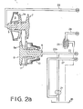
- Figures 2a and 2b are schematic diagrams showing a control system according to the present invention;
- Figures 3a and 3b are block diagrams showing a control unit; and
- Figure 4 is a graph showing variations of clutch current and line pressure.
- Referring to Fig. 1, a motor vehicle is provided with an engine 1, an
electromagnetic powder clutch 2 for transmitting the power of the engine to a continuously variable belt-drive transmission 4 through a selector mechanism 3. - The belt-
drive transmission 4 has a main shaft 5 and an output shaft 6 provided in parallel with the main shaft 5. A drive pulley (primary pulley) 7 and a driven pulley (secondary pulley) 8 are mounted on shafts 5 and 6 respectively. A fixed conical disc 7b of the drive pulley 7 is integral with main shaft 5 and an axially movableconical disc 7a is axially slidably mounted on the main shaft 5. The movableconical disc 7a also slides in acylinder 9a formed on the main shaft 5 to provide a servo device. A chamber 9 of the servo device communicates with ahydraulic circuit 20. - A fixed
conical disc 8b of the drivenpulley 8 is formed on the output shaft 6 opposite a movableconical disc 8a. Theconical disc 8a has a cylindrical portion which is slidably engaged in acylinder 6a of the output shaft 6 to form a servo device. Achamber 10 of the servo device is also communicated- withcontrol circuit 20. Adrive belt 11 engages with the drive pulley 7 and the drivenpulley 8. - Secured to the output shaft 6 is a
drive gear 12 which engages with anintermediate reduction gear 13 on anintermediate shaft 14. Anintermediate gear 15 on theshaft 14 engages with afinal gear 16. The rotation of thefinal gear 16 is transmitted toaxles 18 ofvehicle driving wheels 19 through adifferential 17. - Referring to Figs. 2a and 2b, chamber 9 of the drive pulley 7 is supplied with pressurized oil by an
oil pump 21 from anoil reservoir 26 passing through aline pressure conduit 22,ports pressure control valve 40, transmissionratio control valve 50, andconduit 23. Thechamber 10 of drivenpulley 8 is applied with pressurized oil through apassage 22b without passing throughvalves conical disc 7a of the drive pulley 7 is so designed that the pressure receiving area thereof is larger than that of movableconical disc 8a of the drivenpulley 8. The linepressure control valve 40 comprises avalve body 41,spool 42, andchambers spool 42 is applied with pressure of the pressurized oil in thechamber 41c supplied through aconduit 31. The other end of thespool 42 is applied with the force of aspring 43 provided between the end of thespool 42 and aretainer 45 the position of which is adjustable by ascrew 44. Theport 41a is communicated with adrain port 41b for adrain passage 27 in accordance with the position of a land of thespool 42. The-drain port 41b communicates withoil reservoir 26 throughpassage 27. - The transmission
ratio control valve 50 comprises avalve body 51,spool 52,spring 53 for urging thespool 52 in the downshift direction. Aport 51b of thevalve body 51 is selectively communicated with a pressureoil supply port 51a or adrain port 51c in accordance with the position of lands ofspool 52. Port 51b communicates with chamber 9 through .conduit 23, andport 51a communicates withport 41e of linepressure control valve 40 through conduit 22a. Thedrain port 51c is communicated with theoil reservoir 26 through aconduit 24 and acheck valve 25. - The system is provided with a
regulator valve 60, and solenoid operated on-offcontrol valves - The
regulator valve 60 comprises avalve body 61, aninlet port 61a connected to thepump 21 throughpassages spool 62, anend chamber 61c connected to thepassage 37, and aspring 63 urging thespool 62 to thechamber 61c. When the pressure of oil in thechamber 61c becomes higher than a set value, thespool 62 is shifted to the left, so that aninlet port 61a communicates with adrain port 61b to drain the oil. Thus, a constant pressure of oil is provided in thepassage 37. - The
passage 37 is communicated with thechamber 41d of linepressure control valve 40 through aconstant pressure passage 38,orifice 65, solenoid operated on-offvalve 66, andpassage 32 having anaccumulator 32a. Further, thepassage 38 is communicated with anend chamber 51d of the transmissionratio control valve 50 through apassage 33, and with anotherend chamber 51e through apassage 34,orifice 67, and solenoid operated on-offvalve 68. The solenoid operated on-offvalve 66 is adapted to be operated by pulses. When energized, avalve 66a opens adrain port 66b. The pulsation of the pressure of oil in thepassage 32 is smoothed byaccumulator 32a. The solenoid operated on-offvalve 68 is the same asvalve 66 in construction and operation. Thecontrol valves control unit 70. Thus, pressure controlled by thecontrol valves chambers - In the transmission
ratio control valve 50, pressure receiving area of thespool 52 atchamber 51e is set to a value larger than the area at thechamber 51d. On the other hand, the control pressure in thechamber 51e can be changed between a maximum value, which is the same as the constant pressure in thechamber 51d, when the duty ratio is 0% and zero by controlling the duty ratio of pulses for operating thecontrol valve 68. The transmissionratio control valve 50 is so arranged that thespool 52 is at a neutral position at a middle duty ratio (for example 50%) and is located in an oil supply position by increasing the duty ratio from the middle duty ratio because of reduction of control pressure in thechamber 51e. Further, the speed of the movement of thespool 52 changes with the magnitude of changing of the duty ratio. Thespool 52 is shifted to an oil drain position by decreasing the duty ratio. It will be understood that when the oil is supplied to the chamber 9, the transmission is upshifted. - Referring to Figs. 3a and 3b, a drive
pulley speed sensor 71, driven pulley speed sensor 72,engine speed sensor 73 and throttlevalve position sensor 74 are provided. Output signals Np and Ns ofsensors 71, 72 are fed to an actualtransmission ratio calculator 75 to produce an actual transmission ratio i in accordance with i = Np / Ns. Output signal N and output signal 6 of the throttlevalve position sensor 74 are fed to a desired transmission ratio table 76. The desired transmission ratio id is fetched from the table 76 in accordance with the signals Ns and θ. On the other hand, the output θ is fed to an acceleration calculator 82 to obtain acceleration θ. The signal of the acceleration 6is supplied to acoefficient setting section 77 to produce a coefficient K. The actual transmission ratio i, desired transmission ratio id and coefficient K from thecoefficient setting section 77 are applied to a transmission ratio changingspeed calculator 78 to produce a transmission ratio changing speed di/dt from the formula di/dt = K(id - i). - The speed di/dt and actual ratio i are applied to a duty ratio table 79 to derive the duty ratio D. The duty ratio D is supplied to the solenoid operated
valve 68 through adriver 80. - On the other hand, the output signal θ of
throttle position sensor 74 and the output Ne ofengine speed sensor 73 are fed to an engine torque calculator 96, so that engine torque T is calculated based on throttle position θ and engine speed Ne. - On the other hand, the actual transmission ratio i from the
calculator 75 is applied to a necessary line pressure table 103 to derive a necessary line pressure PLU per unit torque. The necessary line pressure PZU and the engine torque T are applied to a desiredline pressure calculator 104 where calculates a desired line pressure PL. - The desired line pressure PL is applied to a duty ratio table 105 through a correcting section 101 to derive a duty ratio DL corresponding to a corrected line pressure PL'. The duty ratio DL is supplied to a
driver 106 which operates the solenoid operated on-offvalve 66 at the duty ratio. - Further, the signal Ne of
engine speed sensor 73 and signal θ ofthrottle position sensor 74 are supplied to avehicle start detector 107 and the output Ns of driven pulley speed sensor 72 is applied to aclutch engagement detector 108. Outputs of bothdetectors calculator 110 to produce a clutch current signal. The clutch current signal is applied to a clutch coil 2a of the clutch 2 through adriver 112 to control the clutch. Further, the clutch current signal is applied to the correcting section 101 through aclutch disengagement detector 102. - In operation, while the vehicle is at a stop, chamber.10 of the driven
pulley 8 is supplied with line pressure throughpassage 22b, and the chamber 9 of the drive pulley 7 is drained, since the N , Ns,θ are zero and duty ratio D is zero, and thespool 52 is at the right end position and thedrain port 51c communicates with the chamber 9 through theconduit 23 as shown in Figs. 2a and 2b. Thus, in the pulley and belt device bf the continuously variable belt-drive transmission, the drivingbelt 11 engages with the drivenpulley 8 at a maximum running diameter to provide the largest transmission ratio (low speed stage). When the accelerator pedal is depressed, thevehicle start detector 107 produces a vehicle start signal. In response to the start signal, thecalculator 110 producestthe clutch current signal. Thus, the clutch current increases progressively with increase of engine speed, so that theelectromagnetic clutch 2 is gradually engaged, transmitting the engine power to the drive pulley 7. The power of the engine is transmitted to the output shaft 6 at the largest transmission ratio by the drivingbelt 11 and drivenpulley 8, and further transmitted to axles of the drivingwheels 19. Thus, the vehicle is started. - At that time the line pressure is at the highest value by the
pressure control valve 40, since the duty ratio for thevalve 66 is large, and thespool 42 of thecontrol valve 40 is at the right end position. When the throttle valve is opened for acceleration, the desired transmission ratio id and transmission ratio changing speed di/dt are calculated bycalculators 76, 78, and duty ratio D is obtained from the table 79. The value of the duty ratio D is larger than the neutral value, so that the pressure in thechamber 51d of thecontrol valve 50 is higher than thechamber 51e. Thus, thespool 52 is shifted to the left to communicate theport 51a withport 51b, so that oil is supplied to the chamber 9 througH.theconduit 23. On the other hand, duty ratio for thecontrol valve 66 is reduced, thereby shifting thespool 42 of thevalve 40 to the left. Theport 41a communicates with theport 41b of thedrain passage 27. Thus, line pressure reduces, and the transmission is upshifted, since oil is still supplied to the chamber 9 through thecontrol valve 50. When the vehiclerspeed (output signal Ns) exceeds a predetermined value,detector 108 produces a clutch engagement signal. By the engagement signal, theclutch 2 is entirely engaged. - The control operation of line pressure will be described hereinafter with reference to Figs. 2a, 2b, 3a, 3b, and 4. From the engine torque table 96, a torque T is obtained in accordance with throttle position θ and engine speed N , which is applied to desired
line pressure calculator 104. The calculator calculates a desired line pressure PL. The solenoid operated on-offvalve 66 is operated at a duty ratio corresponding to the desired line pressure PL. The line pressure is applied tochamber 10 to hold thebelt 11 at a necessary minimum force, the transmitting torque at which is slightly larger than torque T. Thus, power is transmitted through the transmission without slipping of the belt. - When the vehicle speed decreases below a predetermined value, the clutch current is cut off to disengage the
clutch 2. When the cutting off of the clutch current continues a predetermined period, theclutch disengagement detector 102 produces a correct signal which is applied to correcting section 101. By the correct signal, correcting section.101 operates to reduce the line pressure from a minimum value Pmin during the driving of the vehicle to an allowable minimum value Po as shown in Figure 4. The minimum value Po is set to a necessary minimum value as to tense the belt, so that when the clutch is re-engaged, the belt transmits the power of the engine to the driving wheels without slipping, thereby smoothly re-starting the vehicle. - As shown in Figure 4, when the accelerator pedal is re-depressed, clutch current increases gradually and line pressure increases to a maximum, value Pmax. Thus, the vehicle can be smoothly started without occurring the slipping of the belt.
- In accordance with the principles of the present invention, since the line pressure is controlled to a necessary minimum value when the vehicle is stationary, the load on the engine is reduced, thereby decreasing vibration of the vehicle body and fuel consumption.
- Although an electromagnetic clutch is employed in the above described embodiment, another type of clutch such as a torque converter can be used.
- While the presently preferred embodiment of the present invention has been shown and described, it is to be understood that this disclosure is for the purpose of illustration and that various changes and modifications may be made within the scope of the appended claims.
Claims (5)
Applications Claiming Priority (2)
| Application Number | Priority Date | Filing Date | Title |
|---|---|---|---|
| JP60258137A JPH0657508B2 (en) | 1985-11-18 | 1985-11-18 | Controller for continuously variable transmission |
| JP258137/85 | 1985-11-18 |
Publications (2)
| Publication Number | Publication Date |
|---|---|
| EP0228800A1 true EP0228800A1 (en) | 1987-07-15 |
| EP0228800B1 EP0228800B1 (en) | 1990-04-18 |
Family
ID=17316028
Family Applications (1)
| Application Number | Title | Priority Date | Filing Date |
|---|---|---|---|
| EP86308969A Expired - Lifetime EP0228800B1 (en) | 1985-11-18 | 1986-11-18 | System for controlling the pressure of oil in a system for a continuously variable transmission |
Country Status (4)
| Country | Link |
|---|---|
| US (1) | US4827804A (en) |
| EP (1) | EP0228800B1 (en) |
| JP (1) | JPH0657508B2 (en) |
| DE (1) | DE3670527D1 (en) |
Cited By (2)
| Publication number | Priority date | Publication date | Assignee | Title |
|---|---|---|---|---|
| DE3829262A1 (en) * | 1987-08-28 | 1989-03-16 | Hitachi Ltd | AUTOMATIC TRANSMISSION FOR VEHICLES |
| DE3939660A1 (en) * | 1988-11-30 | 1990-05-31 | Suzuki Motor Co | DEVICE FOR CONTROLLING THE CLUTCH PRESSURE FOR A CONTINUOUSLY TRANSMISSION |
Families Citing this family (4)
| Publication number | Priority date | Publication date | Assignee | Title |
|---|---|---|---|---|
| JP2502241Y2 (en) * | 1988-04-11 | 1996-06-19 | 日産自動車 株式会社 | Line pressure control device for V-belt type continuously variable transmission |
| DE4232233A1 (en) * | 1991-09-27 | 1993-04-08 | Suzuki Motor Co | CONTROL UNIT FOR A CONTINUOUSLY VARIABLE GEARBOX FOR VEHICLES AND RELATED CONTROL METHOD |
| JPH08285022A (en) * | 1995-04-10 | 1996-11-01 | Unisia Jecs Corp | Control device for continuously variable transmission |
| FR2799255B1 (en) * | 1999-10-04 | 2006-09-08 | Luk Lamellen & Kupplungsbau | GEARBOX, ESPECIALLY AUTOMATIC GEARBOX WITH DEVICE FOR REGULATING THE VOLUME FLOW. |
Citations (4)
| Publication number | Priority date | Publication date | Assignee | Title |
|---|---|---|---|---|
| EP0061732A2 (en) * | 1981-03-28 | 1982-10-06 | Nissan Motor Co., Ltd. | Hydraulic control system for continuously variable V-belt transmission with hydrodynamic transmission unit |
| US4369675A (en) * | 1978-11-13 | 1983-01-25 | Van Doorne's Transmissie B.V. | Method and apparatus for controlling an infinitely variable transmission of a motor vehicle |
| JPS5888252A (en) * | 1981-11-20 | 1983-05-26 | Nissan Motor Co Ltd | Line-pressure control method for v-belt type stepless transmission |
| GB2145785A (en) * | 1983-08-31 | 1985-04-03 | Fuji Heavy Ind Ltd | A system for controlling the transmission ratio of an infinitely variable belt-drive transmission |
Family Cites Families (15)
| Publication number | Priority date | Publication date | Assignee | Title |
|---|---|---|---|---|
| US4387608A (en) * | 1979-09-12 | 1983-06-14 | Robert Bosch Gmbh | Electronic control for a stepless vehicle transmission using a control member response to dynamic pressure |
| US4522086A (en) * | 1981-04-24 | 1985-06-11 | Borg-Warner Corporation | Control system for continuously variable transmission |
| US4459878A (en) * | 1982-05-21 | 1984-07-17 | Aisin Seiki Kabushiki Kaisha | Control system and method for a power delivery system having a continuously variable ratio transmission |
| JPS5969563A (en) * | 1982-10-09 | 1984-04-19 | Fuji Heavy Ind Ltd | Controller for stepless speed change gear equipped with electromagnetic powder type clutch |
| JPS59175664A (en) * | 1983-03-23 | 1984-10-04 | Fuji Heavy Ind Ltd | Speed change controller of stepless speed change gear |
| JPS6053256A (en) * | 1983-08-31 | 1985-03-26 | Fuji Heavy Ind Ltd | Controller for kickdown of stepless transmission |
| JPS6053262A (en) * | 1983-09-01 | 1985-03-26 | Toyota Motor Corp | Velocity ratio controller for continuously variable transmission of vehicle |
| JPS6095262A (en) * | 1983-10-28 | 1985-05-28 | Toyota Motor Corp | Hydraulic control method and apparatus for belt type continuously variable transmission |
| JPS6095263A (en) * | 1983-10-29 | 1985-05-28 | Mazda Motor Corp | Control device of continuously variable transmission |
| JPH065095B2 (en) * | 1984-01-27 | 1994-01-19 | トヨタ自動車株式会社 | Hydraulic control system for automobile belt type continuously variable transmission |
| JPS60222649A (en) * | 1984-04-19 | 1985-11-07 | 富士重工業株式会社 | Controller for change gear ratio of electronic type infinitely variable gear |
| JP2506630B2 (en) * | 1984-09-13 | 1996-06-12 | アイシン精機株式会社 | CVT control method |
| JPS61119861A (en) * | 1984-11-16 | 1986-06-07 | Fuji Heavy Ind Ltd | Electronic control device for continuously variable transmission |
| JPS61132431A (en) * | 1984-11-30 | 1986-06-19 | Mazda Motor Corp | Line pressure control device in stepless speed change unit |
| JPS6252261A (en) * | 1985-08-30 | 1987-03-06 | Fuji Heavy Ind Ltd | Oil pressure control device for continuously variable transmission |
-
1985
- 1985-11-18 JP JP60258137A patent/JPH0657508B2/en not_active Expired - Lifetime
-
1986
- 1986-11-10 US US06/928,983 patent/US4827804A/en not_active Expired - Lifetime
- 1986-11-18 DE DE8686308969T patent/DE3670527D1/en not_active Expired - Fee Related
- 1986-11-18 EP EP86308969A patent/EP0228800B1/en not_active Expired - Lifetime
Patent Citations (4)
| Publication number | Priority date | Publication date | Assignee | Title |
|---|---|---|---|---|
| US4369675A (en) * | 1978-11-13 | 1983-01-25 | Van Doorne's Transmissie B.V. | Method and apparatus for controlling an infinitely variable transmission of a motor vehicle |
| EP0061732A2 (en) * | 1981-03-28 | 1982-10-06 | Nissan Motor Co., Ltd. | Hydraulic control system for continuously variable V-belt transmission with hydrodynamic transmission unit |
| JPS5888252A (en) * | 1981-11-20 | 1983-05-26 | Nissan Motor Co Ltd | Line-pressure control method for v-belt type stepless transmission |
| GB2145785A (en) * | 1983-08-31 | 1985-04-03 | Fuji Heavy Ind Ltd | A system for controlling the transmission ratio of an infinitely variable belt-drive transmission |
Cited By (3)
| Publication number | Priority date | Publication date | Assignee | Title |
|---|---|---|---|---|
| DE3829262A1 (en) * | 1987-08-28 | 1989-03-16 | Hitachi Ltd | AUTOMATIC TRANSMISSION FOR VEHICLES |
| DE3829262C2 (en) * | 1987-08-28 | 1994-11-17 | Hitachi Ltd | Automatic transmissions for vehicles and control procedures therefor |
| DE3939660A1 (en) * | 1988-11-30 | 1990-05-31 | Suzuki Motor Co | DEVICE FOR CONTROLLING THE CLUTCH PRESSURE FOR A CONTINUOUSLY TRANSMISSION |
Also Published As
| Publication number | Publication date |
|---|---|
| EP0228800B1 (en) | 1990-04-18 |
| JPH0657508B2 (en) | 1994-08-03 |
| JPS62116322A (en) | 1987-05-27 |
| US4827804A (en) | 1989-05-09 |
| DE3670527D1 (en) | 1990-05-23 |
Similar Documents
| Publication | Publication Date | Title |
|---|---|---|
| US4764156A (en) | System for controlling transmission ratio of a continuously variable transmission for a motor vehicle | |
| US4734082A (en) | System for controlling the pressure of oil in a system for continuously variable transmission | |
| EP0213852B1 (en) | Continuously variable transmission oil pressure control | |
| US4784021A (en) | Control system for a infinitely variable transmission | |
| US4803900A (en) | Transmission ratio control system for a continuously variable transmission | |
| EP0214821B1 (en) | Continuously variable transmission oil pressure control system | |
| EP0228897B1 (en) | Transmission ratio control system for a continuously variable transmission | |
| US4759236A (en) | System for controlling the pressure of oil in a system for a continuously variable transmission | |
| US4730522A (en) | System for controlling the pressure of oil in a system for a continuously variable transmission | |
| US4708031A (en) | Transmission ratio control system for a continuously variable transmission | |
| US4781655A (en) | System for controlling the pressure of oil in a system for a continuously variable transmission | |
| EP0233781B1 (en) | Transmission ratio control system for a continuously variable transmission | |
| EP0239365A2 (en) | Transmission ratio control system for a continuously variable transmission | |
| EP0207227B1 (en) | Control system for an infinitely variable transmission | |
| US4730518A (en) | System for the transmission ratio of a continuously variable transmission | |
| EP0260117A1 (en) | Transmission ratio control system for a continuously variable transmission | |
| US4721019A (en) | Control system for an infinitely variable transmission | |
| US4751857A (en) | System for controlling the pressure of oil in a system for an infinitely variable transmission | |
| EP0231058B1 (en) | A control system for a continuously variable transmission for a motor vehicle | |
| EP0207228B1 (en) | Control system for an infinitely variable transmission | |
| US4827804A (en) | System for controlling the pressure of oil in a system for a continuously variable transmission | |
| US4760760A (en) | Control system for a continuously variable transmission | |
| US4710151A (en) | System for controlling the pressure of oil in a system for a continuously variable transmission |
Legal Events
| Date | Code | Title | Description |
|---|---|---|---|
| PUAI | Public reference made under article 153(3) epc to a published international application that has entered the european phase |
Free format text: ORIGINAL CODE: 0009012 |
|
| 17P | Request for examination filed |
Effective date: 19861128 |
|
| AK | Designated contracting states |
Kind code of ref document: A1 Designated state(s): DE FR GB IT NL SE |
|
| 17Q | First examination report despatched |
Effective date: 19881011 |
|
| GRAA | (expected) grant |
Free format text: ORIGINAL CODE: 0009210 |
|
| AK | Designated contracting states |
Kind code of ref document: B1 Designated state(s): DE FR GB IT NL SE |
|
| ET | Fr: translation filed | ||
| REF | Corresponds to: |
Ref document number: 3670527 Country of ref document: DE Date of ref document: 19900523 |
|
| ITF | It: translation for a ep patent filed |
Owner name: STUDIO CONS. BREVETTUALE S.R.L. |
|
| PLBE | No opposition filed within time limit |
Free format text: ORIGINAL CODE: 0009261 |
|
| STAA | Information on the status of an ep patent application or granted ep patent |
Free format text: STATUS: NO OPPOSITION FILED WITHIN TIME LIMIT |
|
| 26N | No opposition filed | ||
| ITTA | It: last paid annual fee | ||
| PGFP | Annual fee paid to national office [announced via postgrant information from national office to epo] |
Ref country code: FR Payment date: 19921027 Year of fee payment: 7 |
|
| PGFP | Annual fee paid to national office [announced via postgrant information from national office to epo] |
Ref country code: SE Payment date: 19921103 Year of fee payment: 7 |
|
| PGFP | Annual fee paid to national office [announced via postgrant information from national office to epo] |
Ref country code: GB Payment date: 19921109 Year of fee payment: 7 |
|
| PGFP | Annual fee paid to national office [announced via postgrant information from national office to epo] |
Ref country code: DE Payment date: 19921125 Year of fee payment: 7 |
|
| PGFP | Annual fee paid to national office [announced via postgrant information from national office to epo] |
Ref country code: NL Payment date: 19921130 Year of fee payment: 7 |
|
| PG25 | Lapsed in a contracting state [announced via postgrant information from national office to epo] |
Ref country code: GB Effective date: 19931118 |
|
| PG25 | Lapsed in a contracting state [announced via postgrant information from national office to epo] |
Ref country code: SE Effective date: 19931119 |
|
| PG25 | Lapsed in a contracting state [announced via postgrant information from national office to epo] |
Ref country code: NL Effective date: 19940601 |
|
| GBPC | Gb: european patent ceased through non-payment of renewal fee |
Effective date: 19931118 |
|
| NLV4 | Nl: lapsed or anulled due to non-payment of the annual fee | ||
| PG25 | Lapsed in a contracting state [announced via postgrant information from national office to epo] |
Ref country code: FR Effective date: 19940729 |
|
| PG25 | Lapsed in a contracting state [announced via postgrant information from national office to epo] |
Ref country code: DE Effective date: 19940802 |
|
| REG | Reference to a national code |
Ref country code: FR Ref legal event code: ST |
|
| EUG | Se: european patent has lapsed |
Ref document number: 86308969.4 Effective date: 19940610 |
|
| PG25 | Lapsed in a contracting state [announced via postgrant information from national office to epo] |
Ref country code: IT Free format text: LAPSE BECAUSE OF NON-PAYMENT OF DUE FEES;WARNING: LAPSES OF ITALIAN PATENTS WITH EFFECTIVE DATE BEFORE 2007 MAY HAVE OCCURRED AT ANY TIME BEFORE 2007. THE CORRECT EFFECTIVE DATE MAY BE DIFFERENT FROM THE ONE RECORDED. Effective date: 20051118 |