EP0228128B1 - Dry-shaving apparatus - Google Patents
Dry-shaving apparatus Download PDFInfo
- Publication number
- EP0228128B1 EP0228128B1 EP86202246A EP86202246A EP0228128B1 EP 0228128 B1 EP0228128 B1 EP 0228128B1 EP 86202246 A EP86202246 A EP 86202246A EP 86202246 A EP86202246 A EP 86202246A EP 0228128 B1 EP0228128 B1 EP 0228128B1
- Authority
- EP
- European Patent Office
- Prior art keywords
- shear plate
- cutting
- rotation
- cutter
- free path
- Prior art date
- Legal status (The legal status is an assumption and is not a legal conclusion. Google has not performed a legal analysis and makes no representation as to the accuracy of the status listed.)
- Expired - Lifetime
Links
- 230000000694 effects Effects 0.000 description 1
- 230000002093 peripheral effect Effects 0.000 description 1
- 230000007704 transition Effects 0.000 description 1
Images

Classifications
-
- B—PERFORMING OPERATIONS; TRANSPORTING
- B26—HAND CUTTING TOOLS; CUTTING; SEVERING
- B26B—HAND-HELD CUTTING TOOLS NOT OTHERWISE PROVIDED FOR
- B26B19/00—Clippers or shavers operating with a plurality of cutting edges, e.g. hair clippers, dry shavers
-
- B—PERFORMING OPERATIONS; TRANSPORTING
- B26—HAND CUTTING TOOLS; CUTTING; SEVERING
- B26B—HAND-HELD CUTTING TOOLS NOT OTHERWISE PROVIDED FOR
- B26B19/00—Clippers or shavers operating with a plurality of cutting edges, e.g. hair clippers, dry shavers
- B26B19/14—Clippers or shavers operating with a plurality of cutting edges, e.g. hair clippers, dry shavers of the rotary-cutter type; Cutting heads therefor; Cutters therefor
- B26B19/16—Clippers or shavers operating with a plurality of cutting edges, e.g. hair clippers, dry shavers of the rotary-cutter type; Cutting heads therefor; Cutters therefor involving a knife cylinder or a knife cone or separate cutting elements moved like a rotating cylinder or a rotating cone
Definitions
- the invention relates to a dry shaving apparatus comprising a housing having a holder for a shear plate formed with hair-entry apertures and a cutter which is rotatable about an axis of rotation which cutter comprises a carrier with cutting elements which are movable relative to the carrier and which at their radial ends each comprise a cutting edge which extends between two axial ends of the cutting element, one axial end being more advanced in the direction of rotation than the other axial end, and which cutter is partly surrounded by the shear plate, every point of a cutting edge at the end of a cutting element of the cutter, as it rotates, following, as part of a revolution, a constrained path defined by the shear plate and every point of a cutting edge following a circular free path about the axis of rotation when the radial ends are clear of the shear plate.
- the object of the invention is characterized in that viewed in the direction of rotation at the more advanced axial end of the axial end of the cutting element the radius of a circular free path of the cutting edge is smaller than the distance from the axis of rotation of the corresponding portion of the shear plate at the location where at said axial end the free path changes into the constrained path.
- the dry-shaving apparatus shown in the Figures comprises a housing 1 with a holder 2 for a shear plate 3 and a cutter 4 which is rotatable relative to the shear plate and which is partly surrounded by the shear plate.
- the shear plate 3 comprises a central portion 5, curved as a circularly cylindrical surface and formed with hair-entry apertures 6 and also comprises peripheral portions 7 and 8 by which the shear plate is secured to the holder.
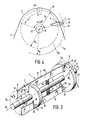
- the cutter 4 comprises a carrier 9 and for example, two cutting elements 10 which are adjustable relative to the carrier. At its radial end 11 each cutting element 10 has a cutting edge 12 which extends between the two axial ends 13 and 14 of the cutting element.
- the carrier 9 comprises a spindle 15 and two discs 16 and 17 mounted on the spindle (Fig. 3). These discs are formed with substantially radial recesses 18 and 19 respectively for the cutting elements 10. At the location of the discs 16 and 17 the cutting elements 10 are formed with slots 20 and 21 respectively. Pins 23 mounted in bores 22 in the discs 16 and 17 extend through the slots 20 and 21 and bridge the recesses 18, 19. In this way the positions of the cutting elements 10 relative to the carrier 9 are radially adjustable to a limited extent. Pressure springs 24 are arranged between the spindle 15 and the cutting elements 10 to exert outwardly directed radial forces on the cutting elements 10.
- the spindle 15 is supported in the holder 2 so as to be rotatable about the axis of the rotation 15'.
- the housing 1 (Fig. 1 accommodates an electric motor 25 for driving the cutter 4.
- the rotation of the motor 25 is transmitted to the cutter 4 by means of pulleys 26 and 27, mounted on the spindle 15 and the motor shaft 28 respectively, and a drive belt 29 tensioned around these pulleys.
- the cutting elements 10 which are not in contact with the shear plate 3 are urged outwards by the springs 24.
- the slots 20 (Fig. 3) are shorter than the slots 21, in such a way that the springs 24 urge the cutting elements 10 less far radially outwards at the location of the disc 16 than at the location of the disc 17.
- the cutting edges 12 are situated on a conical surface.
- the recesses 18 and 19 are offset from each other in the direction of rotation so that in the direction of rotation indicated by the arrow P the axial end 13 is more advanced than the axial end 14 of the cutting element 10.
- the cutting edge 12 consequently has a helical shape.
- a radial end 11 of a cutting element 10 When the cutter 4 is rotated a radial end 11 of a cutting element 10 will be in contact with the inner side 13 of the shear plate 3 during a part of a revolution (Fig. 4). During every revolution each point of the cutting edge 12 of the cutting element 10 will therefore follow a constrained path which is determined by the shear plate 3, and it will follow a free path when the end 11 is clear of the shear plate.
- This free path will be an arc of a circle having a centre situated on the axis of rotation 15' of the spindle 15.
- the free path C A of a point A at the end 13 of a cutting element 10 will have a radius R A which is smaller than the radius R B of the free path C B of point B at the axial end 14 (see also Fig. 3).
- Fig. 4 the free paths C A and C B are represented by arcs of cicle shown in broken lines.
- the central portion of the shear plate is represented as an arc of circle 5 having a central angle a of 150° and a centre situated on the axis of rotation 15'.
- the value of the radius R K of the central portion 5 is selected to lie between the values of R A and R B .
Abstract
Description
- The invention relates to a dry shaving apparatus comprising a housing having a holder for a shear plate formed with hair-entry apertures and a cutter which is rotatable about an axis of rotation which cutter comprises a carrier with cutting elements which are movable relative to the carrier and which at their radial ends each comprise a cutting edge which extends between two axial ends of the cutting element, one axial end being more advanced in the direction of rotation than the other axial end, and which cutter is partly surrounded by the shear plate, every point of a cutting edge at the end of a cutting element of the cutter, as it rotates, following, as part of a revolution, a constrained path defined by the shear plate and every point of a cutting edge following a circular free path about the axis of rotation when the radial ends are clear of the shear plate.
- Such a dry-shaving apparatus is disclosed in for example, US-A-3,710,442. At the transition where the ends of the cutting elements in this known apparatus change over from the free path to the constrained path the sudden contact between the cutting elements and the shear plate will give rise to undesired vibrations in the cutter, which may lead to damage to this cutter, the shear plate and other parts of the apparatus.
- It is the object of the invention to mitigate this drawback and to this end the invention is characterized in that viewed in the direction of rotation at the more advanced axial end of the axial end of the cutting element the radius of a circular free path of the cutting edge is smaller than the distance from the axis of rotation of the corresponding portion of the shear plate at the location where at said axial end the free path changes into the constrained path.
- Special embodiments of the invention are defined in the appended subsidiary Claims.
- An embodiment of the invention will now be described in more detail, by way of example, with reference to the accompanying drawings.
- In the drawings
- Fig. 1 is a schematic longitudinal sectional view of a dry-shaving apparatus in accordance with the invention.
- Fig. 2 is a part of a sectional view taken of the line II-II in Fig. 1.
- Fig. 3 is an enlarged-scale perspective view of the cutter used in the embodiments shown in Figs. 1 and 2.
- Fig. 4 is an enlarged-scale schematic cross- sectional view similar to Fig. 2, showing the shear plate and the cutter used in the embodiment shown in Figs. 1 to 3.
- The dry-shaving apparatus shown in the Figures comprises a housing 1 with a
holder 2 for ashear plate 3 and a cutter 4 which is rotatable relative to the shear plate and which is partly surrounded by the shear plate. - The
shear plate 3 comprises acentral portion 5, curved as a circularly cylindrical surface and formed with hair-entry apertures 6 and also comprisesperipheral portions 7 and 8 by which the shear plate is secured to the holder. - The cutter 4 comprises a
carrier 9 and for example, twocutting elements 10 which are adjustable relative to the carrier. At itsradial end 11 eachcutting element 10 has acutting edge 12 which extends between the twoaxial ends - The
carrier 9 comprises aspindle 15 and twodiscs radial recesses cutting elements 10. At the location of thediscs cutting elements 10 are formed withslots 20 and 21 respectively. Pins 23 mounted inbores 22 in thediscs slots 20 and 21 and bridge therecesses cutting elements 10 relative to thecarrier 9 are radially adjustable to a limited extent.Pressure springs 24 are arranged between thespindle 15 and thecutting elements 10 to exert outwardly directed radial forces on thecutting elements 10. - The
spindle 15 is supported in theholder 2 so as to be rotatable about the axis of the rotation 15'. The housing 1 (Fig. 1 accommodates anelectric motor 25 for driving the cutter 4. The rotation of themotor 25 is transmitted to the cutter 4 by means ofpulleys spindle 15 and themotor shaft 28 respectively, and adrive belt 29 tensioned around these pulleys. - The
cutting elements 10 which are not in contact with theshear plate 3 are urged outwards by thesprings 24. The slots 20 (Fig. 3) are shorter than the slots 21, in such a way that thesprings 24 urge thecutting elements 10 less far radially outwards at the location of thedisc 16 than at the location of thedisc 17. As a result of this, thecutting edges 12 are situated on a conical surface. - The
recesses axial end 13 is more advanced than theaxial end 14 of thecutting element 10. Thecutting edge 12 consequently has a helical shape. - When the cutter 4 is rotated a
radial end 11 of acutting element 10 will be in contact with theinner side 13 of theshear plate 3 during a part of a revolution (Fig. 4). During every revolution each point of thecutting edge 12 of thecutting element 10 will therefore follow a constrained path which is determined by theshear plate 3, and it will follow a free path when theend 11 is clear of the shear plate. This free path will be an arc of a circle having a centre situated on the axis of rotation 15' of thespindle 15. - The free path CA of a point A at the
end 13 of acutting element 10 will have a radius RA which is smaller than the radius RB of the free path CB of point B at the axial end 14 (see also Fig. 3). - In Fig. 4 the free paths CA and CB are represented by arcs of cicle shown in broken lines. The central portion of the shear plate is represented as an arc of
circle 5 having a central angle a of 150° and a centre situated on the axis of rotation 15'. The value of the radius RK of thecentral portion 5 is selected to lie between the values of RA and RB. - Forthe direction of rotation P (Fig. 3) ofthe cutter 4 the
axial ends 13 of thecutting elements 10 are more advanced and point A is the first point reaching thecentral portion 5 of theshear plate 3 from the free path. Since RA is smaller than Rk or, generally speaking, RA is smallerthan the distance from the axis of rotation 15' to the corresponding portion of theshear plate 3 at the location where the free path at theend 13 changes over to the constrained path, point A will initially not be in contact with the inner side of the shear plate. The first contact between thecutting edge 12 and theinnerside 30 of the portion 5will be obtained atthe location of point C where the radius Rc of the free path is equal to Rk. As the rotation of the cutter 4 continues thepressure spring 24 will be compressed and thecutting element 10 will be tilted until the entirecutting edge 12 engages againsttheinner side 30 of theportion 5 of theshear plate 3. For a cutting element 10' this position is shown in broken lines in Fig. 4. In this way a gradual contact of the cutting element with the shear plate is obtained, thereby precluding vibration and collision effects. Since everycutting element 10 is in contact with theshear plate 3 for only a part of a revolution of the cutter 4, frictional losses are minimised. It is obvious thatthe same result can be obtained if the helically shaped cutting edges of the cutting elements are situated on a circularly cylindrical surface and the curved portion of the shear plate has the shape of a conical surface.
Claims (4)
Priority Applications (1)
| Application Number | Priority Date | Filing Date | Title |
|---|---|---|---|
| AT86202246T ATE51564T1 (en) | 1985-12-20 | 1986-12-12 | DRY SHAVER. |
Applications Claiming Priority (2)
| Application Number | Priority Date | Filing Date | Title |
|---|---|---|---|
| NL8503520A NL8503520A (en) | 1985-12-20 | 1985-12-20 | SHAVER. |
| NL8503520 | 1985-12-20 |
Publications (2)
| Publication Number | Publication Date |
|---|---|
| EP0228128A1 EP0228128A1 (en) | 1987-07-08 |
| EP0228128B1 true EP0228128B1 (en) | 1990-04-04 |
Family
ID=19847044
Family Applications (1)
| Application Number | Title | Priority Date | Filing Date |
|---|---|---|---|
| EP86202246A Expired - Lifetime EP0228128B1 (en) | 1985-12-20 | 1986-12-12 | Dry-shaving apparatus |
Country Status (9)
| Country | Link |
|---|---|
| US (1) | US4707915A (en) |
| EP (1) | EP0228128B1 (en) |
| JP (1) | JPS62152495A (en) |
| KR (1) | KR940005312B1 (en) |
| AT (1) | ATE51564T1 (en) |
| CA (1) | CA1259178A (en) |
| DE (1) | DE3670032D1 (en) |
| ES (1) | ES2015262B3 (en) |
| NL (1) | NL8503520A (en) |
Families Citing this family (8)
| Publication number | Priority date | Publication date | Assignee | Title |
|---|---|---|---|---|
| EP0230075B1 (en) * | 1985-12-20 | 1990-04-04 | Koninklijke Philips Electronics N.V. | Dry-shaving apparatus |
| NL8700186A (en) * | 1987-01-27 | 1988-08-16 | Philips Nv | SHAVER. |
| NL8700515A (en) * | 1987-03-04 | 1988-10-03 | Philips Nv | SHAVER. |
| NL8802311A (en) * | 1988-09-19 | 1990-04-17 | Philips Nv | SHAVER. |
| US5014428A (en) * | 1989-03-06 | 1991-05-14 | Kyushu Hitachi Maxell, Ltd. | Rotary type electric razor |
| US6158125A (en) * | 1999-02-22 | 2000-12-12 | Dolev; Moshe | Cutter assemblies for electric shavers |
| US20060200991A1 (en) * | 2005-03-14 | 2006-09-14 | C.C. & L Company Limited | Hair trimmer |
| US8341846B1 (en) * | 2008-11-24 | 2013-01-01 | Lonnie Holmes | Hair clippers with electrically adjustable blades |
Family Cites Families (7)
| Publication number | Priority date | Publication date | Assignee | Title |
|---|---|---|---|---|
| US2375521A (en) * | 1938-08-11 | 1945-05-08 | Gardner W Pearson | Power razor |
| US2332405A (en) * | 1939-05-27 | 1943-10-19 | Roscoe J Smith | Electric shaver |
| US3360857A (en) * | 1965-10-01 | 1968-01-02 | Jerry A. Fortenberry | Rotary dry shaver having an adjustable shear member |
| BE759429A (en) * | 1969-12-05 | 1971-04-30 | Carinthia Elektrogeraete Gmbh | DRY RAZOR |
| US3997233A (en) * | 1976-02-19 | 1976-12-14 | E. I. Du Pont De Nemours And Company | Flat conductor cable connector |
| US4043036A (en) * | 1977-01-27 | 1977-08-23 | Alpha Nova Development Corporation | Power driven shaver |
| JPS5997692A (en) * | 1982-11-26 | 1984-06-05 | セイコーエプソン株式会社 | Electric razor |
-
1985
- 1985-12-20 NL NL8503520A patent/NL8503520A/en not_active Application Discontinuation
-
1986
- 1986-12-12 DE DE8686202246T patent/DE3670032D1/en not_active Expired - Lifetime
- 1986-12-12 ES ES86202246T patent/ES2015262B3/en not_active Expired - Lifetime
- 1986-12-12 EP EP86202246A patent/EP0228128B1/en not_active Expired - Lifetime
- 1986-12-12 AT AT86202246T patent/ATE51564T1/en not_active IP Right Cessation
- 1986-12-16 US US06/943,475 patent/US4707915A/en not_active Expired - Fee Related
- 1986-12-17 KR KR1019860010816A patent/KR940005312B1/en not_active IP Right Cessation
- 1986-12-17 JP JP61299005A patent/JPS62152495A/en active Pending
- 1986-12-17 CA CA000525524A patent/CA1259178A/en not_active Expired
Also Published As
| Publication number | Publication date |
|---|---|
| NL8503520A (en) | 1987-07-16 |
| US4707915A (en) | 1987-11-24 |
| CA1259178A (en) | 1989-09-12 |
| ATE51564T1 (en) | 1990-04-15 |
| ES2015262B3 (en) | 1990-08-16 |
| KR870005758A (en) | 1987-07-07 |
| DE3670032D1 (en) | 1990-05-10 |
| JPS62152495A (en) | 1987-07-07 |
| EP0228128A1 (en) | 1987-07-08 |
| KR940005312B1 (en) | 1994-06-16 |
Similar Documents
| Publication | Publication Date | Title |
|---|---|---|
| EP0566234B1 (en) | Electric razor | |
| EP0228128B1 (en) | Dry-shaving apparatus | |
| EP0557106B1 (en) | Ultrasonic driving motors | |
| EP0230074B1 (en) | Dry-shaving apparatus | |
| EP0230075B1 (en) | Dry-shaving apparatus | |
| EP0360332B1 (en) | Shaving apparatus | |
| US4707923A (en) | Shaving apparatus | |
| EP0285191B1 (en) | Shaving apparatus | |
| EP0246367A2 (en) | Dry shaving apparatus | |
| EP0228127B1 (en) | Dry-shaving apparatus | |
| EP0111967B1 (en) | Shaving apparatus | |
| EP0197572B1 (en) | Shaving appliance | |
| SU774826A1 (en) | Tool for stripping surfaces | |
| SU1390029A1 (en) | Blade disc | |
| SU1600836A1 (en) | Mincing machine | |
| JPH0255078A (en) | Hair cutting device | |
| NL8602606A (en) | Hand held dry-shaver - comprises housing holder for shear plate and rotatable cutter with cutting blades |
Legal Events
| Date | Code | Title | Description |
|---|---|---|---|
| PUAI | Public reference made under article 153(3) epc to a published international application that has entered the european phase |
Free format text: ORIGINAL CODE: 0009012 |
|
| AK | Designated contracting states |
Kind code of ref document: A1 Designated state(s): AT CH DE ES FR GB IT LI NL |
|
| 17P | Request for examination filed |
Effective date: 19871223 |
|
| 17Q | First examination report despatched |
Effective date: 19890116 |
|
| GRAA | (expected) grant |
Free format text: ORIGINAL CODE: 0009210 |
|
| AK | Designated contracting states |
Kind code of ref document: B1 Designated state(s): AT CH DE ES FR GB IT LI NL |
|
| REF | Corresponds to: |
Ref document number: 51564 Country of ref document: AT Date of ref document: 19900415 Kind code of ref document: T |
|
| REF | Corresponds to: |
Ref document number: 3670032 Country of ref document: DE Date of ref document: 19900510 |
|
| ITF | It: translation for a ep patent filed |
Owner name: ING. C. GREGORJ S.P.A. |
|
| ET | Fr: translation filed | ||
| PLBE | No opposition filed within time limit |
Free format text: ORIGINAL CODE: 0009261 |
|
| STAA | Information on the status of an ep patent application or granted ep patent |
Free format text: STATUS: NO OPPOSITION FILED WITHIN TIME LIMIT |
|
| 26N | No opposition filed | ||
| PG25 | Lapsed in a contracting state [announced via postgrant information from national office to epo] |
Ref country code: NL Effective date: 19910701 |
|
| NLV4 | Nl: lapsed or anulled due to non-payment of the annual fee | ||
| ITTA | It: last paid annual fee | ||
| PGFP | Annual fee paid to national office [announced via postgrant information from national office to epo] |
Ref country code: GB Payment date: 19941130 Year of fee payment: 9 |
|
| PGFP | Annual fee paid to national office [announced via postgrant information from national office to epo] |
Ref country code: ES Payment date: 19941205 Year of fee payment: 9 |
|
| PGFP | Annual fee paid to national office [announced via postgrant information from national office to epo] |
Ref country code: FR Payment date: 19941221 Year of fee payment: 9 Ref country code: AT Payment date: 19941221 Year of fee payment: 9 |
|
| PGFP | Annual fee paid to national office [announced via postgrant information from national office to epo] |
Ref country code: DE Payment date: 19950222 Year of fee payment: 9 |
|
| PGFP | Annual fee paid to national office [announced via postgrant information from national office to epo] |
Ref country code: CH Payment date: 19950321 Year of fee payment: 9 |
|
| ITPR | It: changes in ownership of a european patent |
Owner name: CAMBIO RAGIONE SOCIALE;PHILIPS ELECTRONICS N.V. |
|
| REG | Reference to a national code |
Ref country code: CH Ref legal event code: PFA Free format text: PHILIPS ELECTRONICS N.V. |
|
| REG | Reference to a national code |
Ref country code: FR Ref legal event code: CD |
|
| PG25 | Lapsed in a contracting state [announced via postgrant information from national office to epo] |
Ref country code: GB Effective date: 19951212 Ref country code: AT Effective date: 19951212 |
|
| PG25 | Lapsed in a contracting state [announced via postgrant information from national office to epo] |
Ref country code: ES Free format text: LAPSE BECAUSE OF THE APPLICANT RENOUNCES Effective date: 19951213 |
|
| PG25 | Lapsed in a contracting state [announced via postgrant information from national office to epo] |
Ref country code: LI Effective date: 19951231 Ref country code: CH Effective date: 19951231 |
|
| GBPC | Gb: european patent ceased through non-payment of renewal fee |
Effective date: 19951212 |
|
| REG | Reference to a national code |
Ref country code: CH Ref legal event code: PL |
|
| PG25 | Lapsed in a contracting state [announced via postgrant information from national office to epo] |
Ref country code: FR Effective date: 19960830 |
|
| PG25 | Lapsed in a contracting state [announced via postgrant information from national office to epo] |
Ref country code: DE Effective date: 19960903 |
|
| REG | Reference to a national code |
Ref country code: FR Ref legal event code: ST |
|
| REG | Reference to a national code |
Ref country code: ES Ref legal event code: FD2A Effective date: 20010402 |
|
| PG25 | Lapsed in a contracting state [announced via postgrant information from national office to epo] |
Ref country code: IT Free format text: LAPSE BECAUSE OF NON-PAYMENT OF DUE FEES;WARNING: LAPSES OF ITALIAN PATENTS WITH EFFECTIVE DATE BEFORE 2007 MAY HAVE OCCURRED AT ANY TIME BEFORE 2007. THE CORRECT EFFECTIVE DATE MAY BE DIFFERENT FROM THE ONE RECORDED. Effective date: 20051212 |