EP0228112B1 - Shock-absorption deformable bumper for motorcars - Google Patents
Shock-absorption deformable bumper for motorcars Download PDFInfo
- Publication number
- EP0228112B1 EP0228112B1 EP86202120A EP86202120A EP0228112B1 EP 0228112 B1 EP0228112 B1 EP 0228112B1 EP 86202120 A EP86202120 A EP 86202120A EP 86202120 A EP86202120 A EP 86202120A EP 0228112 B1 EP0228112 B1 EP 0228112B1
- Authority
- EP
- European Patent Office
- Prior art keywords
- shield
- deformable bumper
- bumper according
- absorbers
- shock
- Prior art date
- Legal status (The legal status is an assumption and is not a legal conclusion. Google has not performed a legal analysis and makes no representation as to the accuracy of the status listed.)
- Expired
Links
Images


Classifications
-
- B—PERFORMING OPERATIONS; TRANSPORTING
- B60—VEHICLES IN GENERAL
- B60R—VEHICLES, VEHICLE FITTINGS, OR VEHICLE PARTS, NOT OTHERWISE PROVIDED FOR
- B60R19/00—Wheel guards; Radiator guards, e.g. grilles; Obstruction removers; Fittings damping bouncing force in collisions
- B60R19/02—Bumpers, i.e. impact receiving or absorbing members for protecting vehicles or fending off blows from other vehicles or objects
- B60R19/24—Arrangements for mounting bumpers on vehicles
- B60R19/26—Arrangements for mounting bumpers on vehicles comprising yieldable mounting means
-
- B—PERFORMING OPERATIONS; TRANSPORTING
- B60—VEHICLES IN GENERAL
- B60R—VEHICLES, VEHICLE FITTINGS, OR VEHICLE PARTS, NOT OTHERWISE PROVIDED FOR
- B60R19/00—Wheel guards; Radiator guards, e.g. grilles; Obstruction removers; Fittings damping bouncing force in collisions
- B60R19/02—Bumpers, i.e. impact receiving or absorbing members for protecting vehicles or fending off blows from other vehicles or objects
- B60R19/04—Bumpers, i.e. impact receiving or absorbing members for protecting vehicles or fending off blows from other vehicles or objects formed from more than one section in a side-by-side arrangement
- B60R19/12—Bumpers, i.e. impact receiving or absorbing members for protecting vehicles or fending off blows from other vehicles or objects formed from more than one section in a side-by-side arrangement vertically spaced
-
- B—PERFORMING OPERATIONS; TRANSPORTING
- B60—VEHICLES IN GENERAL
- B60R—VEHICLES, VEHICLE FITTINGS, OR VEHICLE PARTS, NOT OTHERWISE PROVIDED FOR
- B60R19/00—Wheel guards; Radiator guards, e.g. grilles; Obstruction removers; Fittings damping bouncing force in collisions
- B60R19/02—Bumpers, i.e. impact receiving or absorbing members for protecting vehicles or fending off blows from other vehicles or objects
- B60R19/24—Arrangements for mounting bumpers on vehicles
- B60R2019/247—Fastening of bumpers' side ends
Definitions
- the present invention relates to a shock absorption deformable bumper for motorcars, and, in particular, it relates to a bumper provided with absorbers (or absorption means) for the energy being evolved in case of low-speed shocks, as defined in the preamble of claim 1 and as disclosed in the document FR-A 2 460 812.
- the bumpers of this type have, above all, the purpose of absorbing, in an anelastic fashion, the most of the kinetic energy which is evolved due to the effect of shocks up to a prefixed speed threshold; that, to the purpose of avoiding that the same bumpers may undergo rebounds, as it would to the contrary occur if they could return to the car all of the energy stored in primitive form.
- the bumpers of the type as described are required to be able, after the shocks up to a determined speed, to returning back to their original conditions, so to be able to withstand further shocks and to again efficaciously absorb the prescribed aliquot of the related kinetic energy.
- the absorbers or the absorpion devices are formed by means for energy dissipation (by friction, by fluid flow and the like) and by elastic means (metal, rubber, compressed-air springs, and the like).
- the energy absorbers are interposed between the bumper and the bodywork of the motorcar and are accomplished by hydraulic shock absorbers incorporating metal springs, with telescopic supports of the oleopneumatic type, with rubber elements having suitable visco-elastic characteristics in order them to be able to retract and to extend according to the prescribed modalities.
- Purpose of the present invention is to improve the bumpers of the described type, reducing the problems connected to the anchoring of the bumper to the bodywork of the motorcar, and those relating to the positioning of the energy absorbers.
- a shock absorption deformable bumper in accordance with the present invention is characterized by the features specified in the characterising portion of claim 1.
- the Applicant has devised to render movable one part only of the bumper, and precisely that part which has the prevailing function of absorbing the kinetic energy due to the longitudinal components of the shock forces.
- the above involves mainly the advantage that one can simplify the system for anchoring the bumper to the bodywork; furthermore, it allows the inertia of the movable portion of the bumper, and, consequently, the size, weight and cost of the energy absorbers, to be reduced, with the efficiency of the same bumper remaining the same.
- the same shield is furthermore superimposed to said spoiler, and protrudes relatively to it.
- the side panels which are stationary, performs the customary action of protecting the car sides
- the shield which is the only movable portion of the bumper, is able to absorb the kinetic energy due to the longitudinal shocks up to a determined speed, besides offering the usual protection of the front or of the rear of the car.
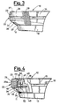
- a front bumper accomplished according to the invention is shown, respectively in front view, top view, side view and sectional view according to path plane IV-IV of Fig. 2;
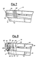
- a rear bumper it too accomplished according to the invention, is respectively shown in front view, top view, side view and sectional view, according to path plane VIII-VIII of Fig. 6.
- a deformable front bumper of a motorcar is generally shown; with 11 a transversal spoiler is indicated, which extends into two longitudinal wings 12 and 13, with which two side guard panels, respectively 14 and 15, are integral. Both the spoiler 11 and the panels 14 and 15 are preferably made from semirigid plastic material.
- the wings 12 and 13 are fastened to the brackets 16 and 17 of the bodywork, partly shown in Fig. 2, by means of bolts 18, 19.
- a movable shield formed by a box-type crossbeam 23 and by and underlying apron 24, which end laterally with angle bars 25 and 26, and protrude forwards relatively to the spoiler 11, as shown in Figs. 3 and 4.
- Both the crossbeam 23 and the apron 24 are made from a rigid plastic material, and the crossbeam is preferably filled with foamed plastic material.
- headlights cleaning devices 27 and 28 are installed, and a hollow 29 to house the license plate and seats 30 and 31 to house the parking lights 32 and 33 are provided.
- a grid of ports 34 is provided, which allow the engine compartment cooling air to reach this latter.
- openings 35 and 36 are provided, into which the shells 37 and 38, integral with the spoiler 11, which house fog lights, not shown, partly penetrate.
- the shield 22 is resting against the spoiler 11, as it results from Fig. 4, and is connected to the side panels 14 and 15 by means of bellows connexions 39 and 40, made, e.g., from rubber.
- bellows connexions 39 and 40 made, e.g., from rubber.
- the shield 22 is constrained to the bodywork by means of energy absorbers 41 and 42, which, in this particular case, are of telescopic and oleopneumatic type.
- the absorbers 41 and 42 comprise a stem, respectively 43 and 44, which is bolted onto the crossbeam by means of a related flange 45 and 46, and screw studs, not shown, integral with the same crossbeam;
- the absorbers 41 and 42 comprise also respective cylinders 47 and 48 which, by means of flanges 49 and 50 and related bolts, not shown, are fastened to the metal-plate brackets 51 and 52 of the bodywork.
- the shield 22, formed by the crossbeam 23 and the apron 24, is able to absorb the kinetic energy due to the longitudinal speed components, because it moves backwards, making absorbers 41 and 42 retract.
- the wings 12 and 13, as well as the panels 14 and 15 perform the usual task of protection of the sides of the motorcar, and the shield 22 performs, in combination, the usual action of protecting the motorcar front, and the particular task of absorbing the shock energy.
- the spoiler 11 performs the usual task of acting as an aerodynamic appendix, and serves to reduce the resistance to the motorcar travelling, and to improve the adherence thereof, at the high travelling speeds.
- the fog lights housing seats are provided in the spoiler 11, so that the same lights can be advantageously mounted in a stationary, and also shock-protected, body.
- a deformable rear bumper realized according to the same criteria as the front bumper shown in Figs. from 1 to 4, but with an obviously different shape, and without certain fittings this latter is provided with; thus, the common elements are indicated with the same numerals, provided with an apex.
- the shield 22' is formed by the only box-type crossbeam 23' and the ornamental sheet 20' is fastened onto the bodywork by screws, not shown.
- the wings 12' and 13' and the panels 14' and 15' are fastened to the metal plates 21 of the bodywork (only partly shown) by means of the bolts 18' and 19' and the absorbers 41' and 42' are fastened to the shield 22' and to the metal plates 21 of the bodywork (always in partial view), by means of screws and bolts not shown.
- the rear bumper 10' performs the same tasks as the front bumper, 10, and behaves in the same way as that.
Landscapes
- Engineering & Computer Science (AREA)
- Mechanical Engineering (AREA)
- Vibration Dampers (AREA)
Description
- The present invention relates to a shock absorption deformable bumper for motorcars, and, in particular, it relates to a bumper provided with absorbers (or absorption means) for the energy being evolved in case of low-speed shocks, as defined in the preamble of claim 1 and as disclosed in the document FR-A 2 460 812.
- The bumpers of this type have, above all, the purpose of absorbing, in an anelastic fashion, the most of the kinetic energy which is evolved due to the effect of shocks up to a prefixed speed threshold; that, to the purpose of avoiding that the same bumpers may undergo rebounds, as it would to the contrary occur if they could return to the car all of the energy stored in primitive form.
- Besides dissipating or absorbing in an irreversible way a portion of the shock energy, the bumpers of the type as described are required to be able, after the shocks up to a determined speed, to returning back to their original conditions, so to be able to withstand further shocks and to again efficaciously absorb the prescribed aliquot of the related kinetic energy.
- Thus, the absorbers or the absorpion devices are formed by means for energy dissipation (by friction, by fluid flow and the like) and by elastic means (metal, rubber, compressed-air springs, and the like).
- Generally, the energy absorbers are interposed between the bumper and the bodywork of the motorcar and are accomplished by hydraulic shock absorbers incorporating metal springs, with telescopic supports of the oleopneumatic type, with rubber elements having suitable visco-elastic characteristics in order them to be able to retract and to extend according to the prescribed modalities.
- Purpose of the present invention is to improve the bumpers of the described type, reducing the problems connected to the anchoring of the bumper to the bodywork of the motorcar, and those relating to the positioning of the energy absorbers.
- To this end, a shock absorption deformable bumper in accordance with the present invention is characterized by the features specified in the characterising portion of claim 1.
- In view of such a purpose, the Applicant has devised to render movable one part only of the bumper, and precisely that part which has the prevailing function of absorbing the kinetic energy due to the longitudinal components of the shock forces.
- The above involves mainly the advantage that one can simplify the system for anchoring the bumper to the bodywork; furthermore, it allows the inertia of the movable portion of the bumper, and, consequently, the size, weight and cost of the energy absorbers, to be reduced, with the efficiency of the same bumper remaining the same.
- Preferably the same shield is furthermore superimposed to said spoiler, and protrudes relatively to it.
- By this solution, the side panels, which are stationary, performs the customary action of protecting the car sides, and the shield, which is the only movable portion of the bumper, is able to absorb the kinetic energy due to the longitudinal shocks up to a determined speed, besides offering the usual protection of the front or of the rear of the car.
- These characteristics and advantages are now illustrated with reference to Figs. from 1 to 8, wherein preferred practical embodiments of the same invention are shown to exemplifying, non-limitative purposes.
- In Figs. from 1 to 4, a front bumper accomplished according to the invention is shown, respectively in front view, top view, side view and sectional view according to path plane IV-IV of Fig. 2;
- In Figs. from 5 to 8, a rear bumper, it too accomplished according to the invention, is respectively shown in front view, top view, side view and sectional view, according to path plane VIII-VIII of Fig. 6.
- In Figs. from 1 to 4, with 10 a deformable front bumper of a motorcar is generally shown; with 11 a transversal spoiler is indicated, which extends into two
longitudinal wings spoiler 11 and thepanels wings brackets bolts - With 22 generally indicated is a movable shield, formed by a box-
type crossbeam 23 and by and underlyingapron 24, which end laterally withangle bars spoiler 11, as shown in Figs. 3 and 4. Both thecrossbeam 23 and theapron 24 are made from a rigid plastic material, and the crossbeam is preferably filled with foamed plastic material. On thecrossbeam 23headlights cleaning devices seats 30 and 31 to house theparking lights ports 34 is provided, which allow the engine compartment cooling air to reach this latter. - In the
apron 24 alsoopenings shells spoiler 11, which house fog lights, not shown, partly penetrate. - The
shield 22 is resting against thespoiler 11, as it results from Fig. 4, and is connected to theside panels bellows connexions section 20a, situated on the rear side of thecrossbeam 23, is fastened. - The
shield 22 is constrained to the bodywork by means of energy absorbers 41 and 42, which, in this particular case, are of telescopic and oleopneumatic type. Theabsorbers related flange absorbers respective cylinders flanges plate brackets - Inasmuch as the absorbers are of known type, the inner structural details thereof are not illustrated.
- In case of a shock up to a determined speed, the
shield 22, formed by thecrossbeam 23 and theapron 24, is able to absorb the kinetic energy due to the longitudinal speed components, because it moves backwards, makingabsorbers - Thereby a compression results of the elastic means, in this particular case of pneumatic type, of the
absorbers 41 and/or 42, which thus accumulate energy in elastic form. - Upon the absorbers extending, a large portion of this energy is dissipated by oil flow through the shock absorber means of the same absorbers, whilst the residual portion serves to bring back the absorbers to their original condition, to be able to withstand further shocks.
- Therefore, by means of the bumper as disclosed, the
wings panels shield 22 performs, in combination, the usual action of protecting the motorcar front, and the particular task of absorbing the shock energy. - The
spoiler 11 performs the usual task of acting as an aerodynamic appendix, and serves to reduce the resistance to the motorcar travelling, and to improve the adherence thereof, at the high travelling speeds. - Furthermore, the fog lights housing seats are provided in the
spoiler 11, so that the same lights can be advantageously mounted in a stationary, and also shock-protected, body. - In Figs. from 5 to 8, shown is a deformable rear bumper, realized according to the same criteria as the front bumper shown in Figs. from 1 to 4, but with an obviously different shape, and without certain fittings this latter is provided with; thus, the common elements are indicated with the same numerals, provided with an apex.
- In this case, the shield 22' is formed by the only box-type crossbeam 23' and the ornamental sheet 20' is fastened onto the bodywork by screws, not shown.
- Furthermore, the wings 12' and 13' and the panels 14' and 15' are fastened to the
metal plates 21 of the bodywork (only partly shown) by means of the bolts 18' and 19' and the absorbers 41' and 42' are fastened to the shield 22' and to themetal plates 21 of the bodywork (always in partial view), by means of screws and bolts not shown. - In case of a shock, the rear bumper 10' performs the same tasks as the front bumper, 10, and behaves in the same way as that.
Claims (7)
Applications Claiming Priority (2)
| Application Number | Priority Date | Filing Date | Title |
|---|---|---|---|
| IT8524252U IT206248Z2 (en) | 1985-12-24 | 1985-12-24 | IMPACT ABSORPTION DEFORMABLE BUMPER FOR VEHICLES. |
| IT2425285U | 1985-12-24 |
Publications (3)
| Publication Number | Publication Date |
|---|---|
| EP0228112A2 EP0228112A2 (en) | 1987-07-08 |
| EP0228112A3 EP0228112A3 (en) | 1988-02-03 |
| EP0228112B1 true EP0228112B1 (en) | 1990-11-14 |
Family
ID=11212764
Family Applications (1)
| Application Number | Title | Priority Date | Filing Date |
|---|---|---|---|
| EP86202120A Expired EP0228112B1 (en) | 1985-12-24 | 1986-11-28 | Shock-absorption deformable bumper for motorcars |
Country Status (4)
| Country | Link |
|---|---|
| US (1) | US4758034A (en) |
| EP (1) | EP0228112B1 (en) |
| DE (1) | DE3675639D1 (en) |
| IT (1) | IT206248Z2 (en) |
Families Citing this family (14)
| Publication number | Priority date | Publication date | Assignee | Title |
|---|---|---|---|---|
| GB2193470A (en) * | 1986-08-06 | 1988-02-10 | Ford Motor Co | Mounting arrangement for a vehicle bumper |
| WO1990002671A2 (en) * | 1988-09-08 | 1990-03-22 | Charles Leicester Whitaker | Spoilers, bumpers and side trims for vehicles |
| US6873643B2 (en) * | 1990-11-16 | 2005-03-29 | Interdigital Technology Corporation | Spread spectrum adaptive power control communications system and method |
| USD382237S (en) * | 1995-10-31 | 1997-08-12 | Lund Industries, Incorporated | Bumper facade for motor vehicle |
| GB2311498A (en) * | 1996-03-29 | 1997-10-01 | Kenneth James Dufty | Impact absorbing bull bar |
| US5769524A (en) * | 1996-12-12 | 1998-06-23 | Yuan; Zhiping | Vehicle lighting systems with side lights |
| US6331068B1 (en) | 1999-02-18 | 2001-12-18 | Lacks Industries, Inc. | Flexible lamp mounting |
| US6502974B2 (en) | 1999-02-18 | 2003-01-07 | Lacks Enterprises, Inc. | Integrated flexible lamp assembly |
| US6190030B1 (en) | 1999-02-18 | 2001-02-20 | Lacks Industries, Inc. | Flexible lamp mounting |
| DE19926346A1 (en) * | 1999-06-09 | 2000-12-14 | Hella Kg Hueck & Co | Headlights |
| FR2811631B1 (en) * | 2000-07-13 | 2002-09-20 | Plastic Omnium Cie | ASSEMBLY OF BODY PARTS, AT LEAST ONE COMPRISING AN OVER-MOLDED FILM |
| EP1223095B1 (en) * | 2000-08-28 | 2006-11-22 | Mitsubishi Heavy Industries, Ltd. | Body structure |
| US6712410B2 (en) * | 2001-08-21 | 2004-03-30 | Ford Global Technologies, Llc | Extruded aluminum bumper |
| US9108686B2 (en) | 2013-11-26 | 2015-08-18 | Honda Motor Co., Ltd. | Air guide assembly for vehicle |
Family Cites Families (12)
| Publication number | Priority date | Publication date | Assignee | Title |
|---|---|---|---|---|
| US3752523A (en) * | 1971-12-27 | 1973-08-14 | H Bierbrauer | Impact absorbing vehicle bumper |
| US3848916A (en) * | 1973-01-18 | 1974-11-19 | Mccord Corp | Bumper assembly |
| DE2330494C2 (en) * | 1973-06-15 | 1982-06-16 | Adam Opel AG, 6090 Rüsselsheim | Bumpers for automobiles |
| US4059301A (en) * | 1976-06-01 | 1977-11-22 | Usm Corporation | Molding retainer |
| IT7953176U1 (en) * | 1979-04-17 | 1980-10-17 | Comind Spa | SUPPORT FOR FOG LIGHTS OF CARS |
| DE2927036A1 (en) * | 1979-07-04 | 1981-01-15 | Daimler Benz Ag | BUMPER FOR VEHICLES |
| JPS5751581A (en) * | 1980-09-08 | 1982-03-26 | Aisin Seiki Co Ltd | Air balancing panel |
| DE3035176A1 (en) * | 1980-09-18 | 1982-04-22 | Volkswagenwerk Ag, 3180 Wolfsburg | Soft nose collision protection for car - has streamlined foam filled bumper on impact absorbing mountings |
| DE3247989A1 (en) * | 1982-12-24 | 1984-06-28 | Volkswagenwerk Ag, 3180 Wolfsburg | One-piece motor-vehicle front end made of plastic |
| DE3331583C2 (en) * | 1983-09-01 | 1986-10-02 | Dr.Ing.H.C. F. Porsche Ag, 7000 Stuttgart | Passenger car rear |
| DE3417337C2 (en) * | 1984-05-10 | 1986-04-24 | Adam Opel AG, 6090 Rüsselsheim | Arrangement of a motor vehicle front part made of plastic on the vehicle body |
| DE8508299U1 (en) * | 1985-03-20 | 1985-07-04 | Bauer, Uwe, 7590 Achern | Spoiler bumper for a motor vehicle |
-
1985
- 1985-12-24 IT IT8524252U patent/IT206248Z2/en active
-
1986
- 1986-11-28 EP EP86202120A patent/EP0228112B1/en not_active Expired
- 1986-11-28 DE DE8686202120T patent/DE3675639D1/en not_active Expired - Fee Related
- 1986-12-17 US US06/942,617 patent/US4758034A/en not_active Expired - Fee Related
Also Published As
| Publication number | Publication date |
|---|---|
| DE3675639D1 (en) | 1990-12-20 |
| EP0228112A3 (en) | 1988-02-03 |
| EP0228112A2 (en) | 1987-07-08 |
| US4758034A (en) | 1988-07-19 |
| IT8524252V0 (en) | 1985-12-24 |
| IT206248Z2 (en) | 1987-07-13 |
Similar Documents
| Publication | Publication Date | Title |
|---|---|---|
| US4758034A (en) | Shock-absorption deformable bumper for motorcars | |
| US4061384A (en) | Bumper having pivotal load spreader plate for deflecting energy absorbing medium | |
| US4213644A (en) | Energy-absorbing bumper assembly | |
| US4460205A (en) | Energy absorbing vehicle bumper assembly | |
| US3926462A (en) | Shock absorbing buffer assembly | |
| US8235433B2 (en) | Bumper shield for a motor vehicle | |
| US3840259A (en) | Bumper arrangement | |
| US20110193357A1 (en) | Bumper arrangement for a motor vehicle | |
| FR2439124A1 (en) | Impact absorbing car front frame - incorporates lower support for bulkhead and upper crush frame | |
| US4778208A (en) | Yielding arrangement of a bumper at the body of a motor vehicle | |
| US3869164A (en) | Vehicle with impact-absorbing end portion | |
| JPS6348741B2 (en) | ||
| US3907351A (en) | Impact-damping system for automotive vehicles | |
| US3830539A (en) | Impact energy absorbing bumper for vehicle | |
| JPS598912Y2 (en) | Shock absorbing bumper structure | |
| CN111516634A (en) | Pedestrian protection leg protection integrated structure | |
| US3891258A (en) | Bumper for motor vehicles | |
| US4098531A (en) | Body for motor vehicles | |
| US3934911A (en) | Vehicle bumper arrangement | |
| CN207790593U (en) | A kind of automobile rear bumper | |
| CN219339390U (en) | High-strength anti-collision automobile bumper | |
| CN212796770U (en) | Protection type car front defence support | |
| CN205632374U (en) | Automobile bumper | |
| CN217969751U (en) | Novel bumper return bend of electric tricycle and frame boundary beam structure | |
| KR20200072095A (en) | Lower stiffener unit for vehicle |
Legal Events
| Date | Code | Title | Description |
|---|---|---|---|
| PUAI | Public reference made under article 153(3) epc to a published international application that has entered the european phase |
Free format text: ORIGINAL CODE: 0009012 |
|
| AK | Designated contracting states |
Kind code of ref document: A2 Designated state(s): DE FR GB |
|
| RAP1 | Party data changed (applicant data changed or rights of an application transferred) |
Owner name: ALFA LANCIA INDUSTRIALE S.R.L. |
|
| PUAL | Search report despatched |
Free format text: ORIGINAL CODE: 0009013 |
|
| AK | Designated contracting states |
Kind code of ref document: A3 Designated state(s): DE FR GB |
|
| RAP1 | Party data changed (applicant data changed or rights of an application transferred) |
Owner name: ALFA LANCIA INDUSTRIALE S.P.A. |
|
| 17P | Request for examination filed |
Effective date: 19880628 |
|
| 17Q | First examination report despatched |
Effective date: 19900222 |
|
| RAP1 | Party data changed (applicant data changed or rights of an application transferred) |
Owner name: ALFA LANCIA S.P.A. |
|
| GRAA | (expected) grant |
Free format text: ORIGINAL CODE: 0009210 |
|
| AK | Designated contracting states |
Kind code of ref document: B1 Designated state(s): DE FR GB |
|
| ET | Fr: translation filed | ||
| REF | Corresponds to: |
Ref document number: 3675639 Country of ref document: DE Date of ref document: 19901220 |
|
| PLBE | No opposition filed within time limit |
Free format text: ORIGINAL CODE: 0009261 |
|
| STAA | Information on the status of an ep patent application or granted ep patent |
Free format text: STATUS: NO OPPOSITION FILED WITHIN TIME LIMIT |
|
| 26N | No opposition filed | ||
| REG | Reference to a national code |
Ref country code: GB Ref legal event code: 732 |
|
| REG | Reference to a national code |
Ref country code: FR Ref legal event code: TP |
|
| PGFP | Annual fee paid to national office [announced via postgrant information from national office to epo] |
Ref country code: GB Payment date: 19941122 Year of fee payment: 9 |
|
| PG25 | Lapsed in a contracting state [announced via postgrant information from national office to epo] |
Ref country code: GB Effective date: 19951128 |
|
| GBPC | Gb: european patent ceased through non-payment of renewal fee |
Effective date: 19951128 |
|
| PGFP | Annual fee paid to national office [announced via postgrant information from national office to epo] |
Ref country code: FR Payment date: 19961030 Year of fee payment: 11 |
|
| PGFP | Annual fee paid to national office [announced via postgrant information from national office to epo] |
Ref country code: DE Payment date: 19970110 Year of fee payment: 11 |
|
| PG25 | Lapsed in a contracting state [announced via postgrant information from national office to epo] |
Ref country code: FR Free format text: THE PATENT HAS BEEN ANNULLED BY A DECISION OF A NATIONAL AUTHORITY Effective date: 19971130 |
|
| PG25 | Lapsed in a contracting state [announced via postgrant information from national office to epo] |
Ref country code: DE Free format text: LAPSE BECAUSE OF NON-PAYMENT OF DUE FEES Effective date: 19980801 |
|
| REG | Reference to a national code |
Ref country code: FR Ref legal event code: ST |