EP0228099B1 - Electrical arc interruption chamber, in particular for fluid-quenched circuit breakers - Google Patents
Electrical arc interruption chamber, in particular for fluid-quenched circuit breakers Download PDFInfo
- Publication number
- EP0228099B1 EP0228099B1 EP86201779A EP86201779A EP0228099B1 EP 0228099 B1 EP0228099 B1 EP 0228099B1 EP 86201779 A EP86201779 A EP 86201779A EP 86201779 A EP86201779 A EP 86201779A EP 0228099 B1 EP0228099 B1 EP 0228099B1
- Authority
- EP
- European Patent Office
- Prior art keywords
- movable
- contact
- arc
- bell
- chamber
- Prior art date
- Legal status (The legal status is an assumption and is not a legal conclusion. Google has not performed a legal analysis and makes no representation as to the accuracy of the status listed.)
- Expired - Lifetime
Links
- 238000010791 quenching Methods 0.000 claims abstract description 13
- 241000722921 Tulipa gesneriana Species 0.000 claims abstract description 6
- 230000000171 quenching effect Effects 0.000 claims description 5
- 239000012777 electrically insulating material Substances 0.000 claims description 2
- 239000011810 insulating material Substances 0.000 abstract description 6
- 239000012530 fluid Substances 0.000 description 4
- 230000000295 complement effect Effects 0.000 description 3
- 230000006835 compression Effects 0.000 description 1
- 238000007906 compression Methods 0.000 description 1
- 238000010438 heat treatment Methods 0.000 description 1
- 238000013021 overheating Methods 0.000 description 1
- 239000007787 solid Substances 0.000 description 1
- SFZCNBIFKDRMGX-UHFFFAOYSA-N sulfur hexafluoride Chemical compound FS(F)(F)(F)(F)F SFZCNBIFKDRMGX-UHFFFAOYSA-N 0.000 description 1
- 229960000909 sulfur hexafluoride Drugs 0.000 description 1
Images


Classifications
-
- H—ELECTRICITY
- H01—ELECTRIC ELEMENTS
- H01H—ELECTRIC SWITCHES; RELAYS; SELECTORS; EMERGENCY PROTECTIVE DEVICES
- H01H33/00—High-tension or heavy-current switches with arc-extinguishing or arc-preventing means
- H01H33/70—Switches with separate means for directing, obtaining, or increasing flow of arc-extinguishing fluid
- H01H33/7015—Switches with separate means for directing, obtaining, or increasing flow of arc-extinguishing fluid characterised by flow directing elements associated with contacts
- H01H33/7023—Switches with separate means for directing, obtaining, or increasing flow of arc-extinguishing fluid characterised by flow directing elements associated with contacts characterised by an insulating tubular gas flow enhancing nozzle
- H01H33/703—Switches with separate means for directing, obtaining, or increasing flow of arc-extinguishing fluid characterised by flow directing elements associated with contacts characterised by an insulating tubular gas flow enhancing nozzle having special gas flow directing elements, e.g. grooves, extensions
-
- H—ELECTRICITY
- H01—ELECTRIC ELEMENTS
- H01H—ELECTRIC SWITCHES; RELAYS; SELECTORS; EMERGENCY PROTECTIVE DEVICES
- H01H33/00—High-tension or heavy-current switches with arc-extinguishing or arc-preventing means
- H01H33/70—Switches with separate means for directing, obtaining, or increasing flow of arc-extinguishing fluid
- H01H33/7007—Switches with separate means for directing, obtaining, or increasing flow of arc-extinguishing fluid wherein the flow is a function of the current being interrupted
Definitions
- the present invention relates to a fluid-quenched circuit breaker.
- FR-A-2 519 470 discloses a fluid quenched circuit breaker in which there are shown a movable arc contact of the "tulip" type, a bell-shaped element of electrically insulating material and two chambers for the passage of the arc quenching fluid.
- US-A-4 289 942 and FR-A-2 518 978 substantially disclose circuit breakers similar to the above mentioned one.
- the energy developed by the electrical arc while heating the gas, decomposes it, generating a pressure which provides a blast of fluid onto the arc, causing it to be quenched.
- interruption chambers are equipped with elements of electrical insulating material, provided with suitably shaped and orientated openings, which allow the gas to circulate under pressure, to accomplish the quenching.
- Such types of chambers due to the difficulty of accomplishing the optimum conditions required for the interruption of the currents throughout the range provided by the operations, i.e., from the small overload up to the highest interruption powers, are characterized by a narrow operation range, i.e., if the dimensioning is designed to interrupt high currents, do not result effective in quenching the lower currents, and vice-versa.
- Purpose of the present invention is to obviate the disadvantages of the cited prior art, by providing a universal interruption chamber, which, on the basis of its inner geometry, allows the necessary gas pressures and speeds, and hence high interruption powers to be generated without losing efficaciousness when the interruption of the lowest overload currents is required.
- the present invention provides a fluid-quenched circuit breaker having the features claimed in claim 1.
- the movable arc contact 11 and the inner surface 37 of the element 12 define a first chamber 13 comprised therebetween.
- the movable arc contact 11 has an upper portion made of petals 14 radially enlarged upwards, and at the connection of which there are provided radial discharge holes 15.
- An intermediate portion 16 radially enlarged to a ring-shape separates a lower threaded portion 17, suitable to be screwed within a complementary seat 18 centrally provided in a body 19 of a movable main contact 20.
- a cylindrical threaded portion 21 protrudes downwards and it can be positioned within a complementary threaded seat 22, provided in the body 19 of the main movable contact 20 and externally concentric to the seat 18.
- the bell-shaped element 12 On its outer surface, the bell-shaped element 12 is provided with protruding portions 23, e.g., with four of them, running along generatrices thereof, bent towards a nozzle 24.
- a second chamber 25 is defined in its upper portion on one side by the element 12 and on the other side by a wall of electrical insulating material 26 having a crown 27, in which there is provided a nozzle-shaped opening 28.
- the lower portion of chamber 25 is defined by the inner walls 29 of the body 19 on one side and on the other side by a corresponding lower outer portion of the element 12
- a set of four holes 30 is positioned on an annular portion 31 of the body 19, concentric to said threaded seats 18 and 22.
- the wall of electrical insulating material 26 and the movable main contact 20 are connected to each other by respective annular, threaded and complementary undercuts 32 and 33 coupled with each other, creating one single outer body.
- the electrical arc is generated between the arc contacts 11 and 11bis,.
- the arc causes it to flow, under pressure, inside the coaxial chambers 13 and 25 and inside the movable arc contact 11.
- the gas flows upwards, passing into a zone 34 at lower speed and pressure, and into a zone 35, of smaller volume, at higher speed and pressure.
- a more uniform and effective gas blast action is obtained, which allows a reduction in the arc-quenching times and hence a lower and more uniform wear of the top portion of element 12.
- the particular profile of the bell-shaped element 12, and in particular the protruding portions 23 allow the gas pressure to be varied in the compression step during the opening of the contacts. As a consequence there is a reduction in the volume of the pumped gas and an increase in capacity of interruption, with the diameters of the stationary arc contact and of the movable arc contact, and the diameters of components 24-27 and 28 being the same.
- the suitably shaped discharge holes 15 allow the generation of a depression in an upper zone 36 of the movable arc contact 11 wherein the arc is generated.
- a depression allows the removal of heat from the zone 36 wherein the arc is generated, increasing the interruption power in that the arc which is generated on contacts opening is cooled more rapidly.
- element 12 is internally and in its lowermost portion provided, with a recessed portion 38, which defines, together with the movable contact 11, a volume greater than that defined by the homologous straight portion 37 of Fig. 3.
- FIG. 6 A further embodiment of the interruption chamber, according to the present invention, is shown in Fig. 6, with a movable contact 111 shaped as to have in its interior a portion 140 made of electrical insulating material, which modifies the gas discharge from the zone 113 towards the direction 141.
- the movable arc contact 111 is housed inside a seat 118 centrally provided in a body 119 of a movable main contact 120.
- a suitably dimensioned annular through-hole 121 is provided, which places the chamber 113 in communication towards the bottom 142 with the remaining of the electrical insulating encasing (not shown).
- the chamber 113 and chamber 142 act, for certain current values, as a function of the diameter of hole 121 and of the volumes of chambers 113 and 142, as a double chamber for receiving the overheated gas, which flows downwards under its self-generated pressure.
- the gas flows through the annular hole 121, quenching of the arc by heat removal from the arc zone during the passage of the arc current is achieved, and subsequently the current is in the proximity of zero.
Landscapes
- Circuit Breakers (AREA)
- Carbon And Carbon Compounds (AREA)
- Rotary Switch, Piano Key Switch, And Lever Switch (AREA)
- Arc-Extinguishing Devices That Are Switches (AREA)
Abstract
Description
- The present invention relates to a fluid-quenched circuit breaker.
- It is to be noted that FR-A-2 519 470 discloses a fluid quenched circuit breaker in which there are shown a movable arc contact of the "tulip" type, a bell-shaped element of electrically insulating material and two chambers for the passage of the arc quenching fluid.
US-A-4 289 942 and FR-A-2 518 978 substantially disclose circuit breakers similar to the above mentioned one. - The energy developed by the electrical arc, while heating the gas, decomposes it, generating a pressure which provides a blast of fluid onto the arc, causing it to be quenched.
- According to known solutions, interruption chambers are equipped with elements of electrical insulating material, provided with suitably shaped and orientated openings, which allow the gas to circulate under pressure, to accomplish the quenching.
- Such types of chambers, due to the difficulty of accomplishing the optimum conditions required for the interruption of the currents throughout the range provided by the operations, i.e., from the small overload up to the highest interruption powers, are characterized by a narrow operation range, i.e., if the dimensioning is designed to interrupt high currents, do not result effective in quenching the lower currents, and vice-versa.
- Purpose of the present invention is to obviate the disadvantages of the cited prior art, by providing a universal interruption chamber, which, on the basis of its inner geometry, allows the necessary gas pressures and speeds, and hence high interruption powers to be generated without losing efficaciousness when the interruption of the lowest overload currents is required.
- In order to achieve such a purpose, the present invention provides a fluid-quenched circuit breaker having the features claimed in claim 1.
- The characteristics and the advantages of the present invention shall appear more clearly from the following disclosure, referred to the attached drawings, wherein:
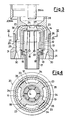
- Fig. 1 is a partially sectional exploded view of a first embodiment of a fluid quenched circuit breaker according to the invention,
- Fig. 2 is a plan view of the intermediate element of Fig. 1,
- Fig. 3 is a sectional elevation view of the elements of Fig. 1, in their assembled condition,
- Fig. 4 is a sectional view along the path IV-IV of Fig. 3,
- Fig. 5 is a sectional elevation view of a second embodiment of the interruption chamber according to the invention, and
- Fig. 6 is a sectional elevation view of a second form of practical embodiment of the interruption chamber according to the present invention.
- Inside a tightly sealed electrical insulating encasing (not shown in the Figures; also other structural parts not strictly relating to the invention have not been shown) containing an arc-quenching gas such as sulphur hexafluoride, there are provided current-bearing connections, respectively bearing a movable
main contact 20 and a stationary main contact 20bis, together with the related arc contact 11 (the movable contact) and 11bis (the stationary contact). - Referring to the figures, there is shown a
movable arc contact 11 of tubular type with longitudinal notches, or more precisely of the tulip type, positioned inside a bell-shaped element 12 of electrical insulating material, solid with the said movable contact, which surrounds it, and is positioned above the saidarc contact 11. - The
movable arc contact 11 and theinner surface 37 of theelement 12 define afirst chamber 13 comprised therebetween. - The
movable arc contact 11 has an upper portion made ofpetals 14 radially enlarged upwards, and at the connection of which there are providedradial discharge holes 15. - An
intermediate portion 16 radially enlarged to a ring-shape separates a lower threadedportion 17, suitable to be screwed within acomplementary seat 18 centrally provided in abody 19 of a movablemain contact 20. - Also from the bell-shaped element 12 a cylindrical threaded
portion 21 protrudes downwards and it can be positioned within a complementary threadedseat 22, provided in thebody 19 of the mainmovable contact 20 and externally concentric to theseat 18. - On its outer surface, the bell-
shaped element 12 is provided with protrudingportions 23, e.g., with four of them, running along generatrices thereof, bent towards anozzle 24. - Coaxially arranged around said
first chamber 13, asecond chamber 25 is defined in its upper portion on one side by theelement 12 and on the other side by a wall of electricalinsulating material 26 having acrown 27, in which there is provided a nozzle-shaped opening 28. - The lower portion of
chamber 25 is defined by theinner walls 29 of thebody 19 on one side and on the other side by a corresponding lower outer portion of the element 12 A set of fourholes 30 is positioned on anannular portion 31 of thebody 19, concentric to said threadedseats - The wall of electrical
insulating material 26 and the movablemain contact 20 are connected to each other by respective annular, threaded andcomplementary undercuts - During the opening of the
main contacts 20 and 20bis, the electrical arc is generated between thearc contacts 11 and 11bis,. By overheating the surrounding arc-quenching medium, the arc causes it to flow, under pressure, inside thecoaxial chambers movable arc contact 11. - In particular, inside the
chamber 25 the gas flows upwards, passing into azone 34 at lower speed and pressure, and into azone 35, of smaller volume, at higher speed and pressure. In this way, in the area wherein the electrical arc is generated, a more uniform and effective gas blast action is obtained, which allows a reduction in the arc-quenching times and hence a lower and more uniform wear of the top portion ofelement 12. - Furthermore, the particular profile of the bell-
shaped element 12, and in particular the protrudingportions 23 allow the gas pressure to be varied in the compression step during the opening of the contacts. As a consequence there is a reduction in the volume of the pumped gas and an increase in capacity of interruption, with the diameters of the stationary arc contact and of the movable arc contact, and the diameters of components 24-27 and 28 being the same. - As to the
chamber 13, the suitably shapeddischarge holes 15 allow the generation of a depression in anupper zone 36 of themovable arc contact 11 wherein the arc is generated. Such a depression allows the removal of heat from thezone 36 wherein the arc is generated, increasing the interruption power in that the arc which is generated on contacts opening is cooled more rapidly. - In another embodiment of the interruption chamber of the invention and shown in Fig. 5,
element 12 is internally and in its lowermost portion provided, with arecessed portion 38, which defines, together with themovable contact 11, a volume greater than that defined by the homologousstraight portion 37 of Fig. 3. - A further embodiment of the interruption chamber, according to the present invention, is shown in Fig. 6, with a
movable contact 111 shaped as to have in its interior aportion 140 made of electrical insulating material, which modifies the gas discharge from thezone 113 towards thedirection 141. In a similar way as in Fig. 3, themovable arc contact 111 is housed inside aseat 118 centrally provided in abody 119 of a movablemain contact 120. - Coaxially with and externally to the seat 118 a suitably dimensioned annular through-
hole 121 is provided, which places thechamber 113 in communication towards thebottom 142 with the remaining of the electrical insulating encasing (not shown). - In such a way, the
chamber 113 andchamber 142 act, for certain current values, as a function of the diameter ofhole 121 and of the volumes ofchambers annular hole 121, quenching of the arc by heat removal from the arc zone during the passage of the arc current is achieved, and subsequently the current is in the proximity of zero.
Claims (4)
- Fluid-quenched circuit breaker wherein, inside a tightly sealed electrical insulating encasing, containing an arc-quenching gas, there are provided current-bearing connections, respectively supporting a movable main contact (20) and a stationary main contact (20bis), each one of said main contacts being provided with its respective arc contact (11, 11bis), said movable arc contact (11) of the tulip type being positioned inside a bell-shaped element (12) of electrically insulating material, said movable arc contact (11) and said bell-shaped element (12) being solidly fixed to each other, and being housed inside the body (19) of the said movable main contact (20), wherein a first chamber (13) for the passage of the arc quenching gas is defined between said movable arc contact (11) and said bell-shaped element (12), and a second chamber (25) for the passage of the said arc-quenching gas is defined between said movable main contact (20) and said bell-shaped element (12), characterized in that said bell-shaped element (12) is provided, on its outer surface, with protruding portions (23) formed along the generatrices thereof, said protruding portions (23) being bent toward a nozzle (24) on its upper surface.
- Fluid-quenched circuit breaker according to claim 1, characterized in that said movable arc contact (11) of the tulip type is provided with petals (14) having an enlarged upper portion.
- Fluid-quenched circuit breaker according to claim 1, characterized in that the said movable arc contact (11) of the tulip type is provided with petals (14) bearing an enlarged upper portion, and with discharge holes (15) positioned at the basis of said petals (14).
- Fluid-quenched circuit breaker according to claim 1 and 3, characterized in that the said first chamber (13) defined between said movable arc contact (11) and said bell-shaped element (12) communicates with said discharge holes (15) provided at the basis of said petals (14) of said movable arc contact (11).
Priority Applications (1)
| Application Number | Priority Date | Filing Date | Title |
|---|---|---|---|
| AT86201779T ATE69909T1 (en) | 1985-12-03 | 1986-10-14 | ARC BREAKING CHAMBER, ESPECIALLY FOR LIQUID EXTINGUISHED CIRCUIT BREAKER. |
Applications Claiming Priority (2)
| Application Number | Priority Date | Filing Date | Title |
|---|---|---|---|
| IT23074/85A IT1186140B (en) | 1985-12-03 | 1985-12-03 | ELECTRIC ARC SWITCH CHAMBER, IN PARTICULAR FOR FLUID SWITCHES |
| IT2307485 | 1985-12-03 |
Publications (3)
| Publication Number | Publication Date |
|---|---|
| EP0228099A2 EP0228099A2 (en) | 1987-07-08 |
| EP0228099A3 EP0228099A3 (en) | 1989-07-05 |
| EP0228099B1 true EP0228099B1 (en) | 1991-11-27 |
Family
ID=11203498
Family Applications (1)
| Application Number | Title | Priority Date | Filing Date |
|---|---|---|---|
| EP86201779A Expired - Lifetime EP0228099B1 (en) | 1985-12-03 | 1986-10-14 | Electrical arc interruption chamber, in particular for fluid-quenched circuit breakers |
Country Status (6)
| Country | Link |
|---|---|
| US (1) | US4716266A (en) |
| EP (1) | EP0228099B1 (en) |
| AT (1) | ATE69909T1 (en) |
| CA (1) | CA1289604C (en) |
| DE (1) | DE3682663D1 (en) |
| IT (1) | IT1186140B (en) |
Cited By (1)
| Publication number | Priority date | Publication date | Assignee | Title |
|---|---|---|---|---|
| EP2887367A1 (en) | 2013-12-19 | 2015-06-24 | ABB Technology AB | Gas-insulated high-voltage circuit breaker |
Families Citing this family (8)
| Publication number | Priority date | Publication date | Assignee | Title |
|---|---|---|---|---|
| JP2771305B2 (en) * | 1990-03-13 | 1998-07-02 | 株式会社日立製作所 | Gas circuit breaker |
| EP0468294B1 (en) * | 1990-07-27 | 1995-09-27 | Hitachi, Ltd. | Puffer type gas-insulated circuit breaker |
| DE19816505A1 (en) * | 1998-04-14 | 1999-10-21 | Asea Brown Boveri | Circuit breaker |
| DE102004047260B4 (en) * | 2004-09-24 | 2006-08-03 | Siemens Ag | Insulating housing with ventilation shaft |
| EP1675144A1 (en) * | 2004-12-23 | 2006-06-28 | ABB Technology AG | High voltage switch with arc resistant short circuit current conductor |
| EP1826792B1 (en) * | 2006-02-28 | 2008-09-03 | ABB Research Ltd | Arcing chamber of a high voltage circuit breaker with a heating volume receiving the arc extinguishing gases generated by the arc |
| CN102714112B (en) * | 2010-02-04 | 2016-01-27 | 三菱电机株式会社 | Gas-break switch |
| DE202015106610U1 (en) | 2015-12-04 | 2016-01-11 | Abb Technology Ag | Contact tulip for a gas-insulated high-voltage switch and high-voltage switch with this contact tulip |
Family Cites Families (5)
| Publication number | Priority date | Publication date | Assignee | Title |
|---|---|---|---|---|
| US4289942A (en) * | 1977-07-29 | 1981-09-15 | Westinghouse Electric Corp. | Gas-blast circuit-interrupter with multiple insulating arc-shield construction |
| US4393291A (en) * | 1979-10-12 | 1983-07-12 | Brush Switchgear Limited | Gas blast interrupters |
| JPS58108624A (en) * | 1981-12-22 | 1983-06-28 | 三菱電機株式会社 | Buffer type gas breaker |
| FR2519470A1 (en) * | 1982-01-05 | 1983-07-08 | Alsthom Atlantique | COMPRESSED GAS CIRCUIT BREAKER |
| US4427862A (en) * | 1982-11-08 | 1984-01-24 | S&C Electric Company | Contact assembly for a high-voltage circuit interrupter |
-
1985
- 1985-12-03 IT IT23074/85A patent/IT1186140B/en active
-
1986
- 1986-10-14 EP EP86201779A patent/EP0228099B1/en not_active Expired - Lifetime
- 1986-10-14 CA CA000520423A patent/CA1289604C/en not_active Expired - Lifetime
- 1986-10-14 DE DE8686201779T patent/DE3682663D1/en not_active Expired - Fee Related
- 1986-10-14 AT AT86201779T patent/ATE69909T1/en not_active IP Right Cessation
- 1986-10-15 US US06/918,879 patent/US4716266A/en not_active Expired - Fee Related
Cited By (1)
| Publication number | Priority date | Publication date | Assignee | Title |
|---|---|---|---|---|
| EP2887367A1 (en) | 2013-12-19 | 2015-06-24 | ABB Technology AB | Gas-insulated high-voltage circuit breaker |
Also Published As
| Publication number | Publication date |
|---|---|
| EP0228099A2 (en) | 1987-07-08 |
| EP0228099A3 (en) | 1989-07-05 |
| CA1289604C (en) | 1991-09-24 |
| IT8523074A0 (en) | 1985-12-03 |
| DE3682663D1 (en) | 1992-01-09 |
| IT1186140B (en) | 1987-11-18 |
| US4716266A (en) | 1987-12-29 |
| ATE69909T1 (en) | 1991-12-15 |
Similar Documents
| Publication | Publication Date | Title |
|---|---|---|
| AU642758B2 (en) | Electrical circuit breaker with rotating arc and self-extinguishing expansion | |
| US4774388A (en) | Compressed dielectric gas circuit breaker | |
| EP0503223B1 (en) | Puffer-type gas circuit breaker | |
| US4286128A (en) | Electric gas-switch | |
| CA2199350A1 (en) | A power circuit breaker with a high-speed bridging contact | |
| US4716266A (en) | Electrical arc quenching chamber, in particular for fluid-quenched circuit breakers | |
| US4453054A (en) | Contact apparatus for vacuum switches | |
| US4553002A (en) | Axial magnetic field vacuum-type circuit interrupter | |
| US4665289A (en) | Puffer type gas insulated circuit breaker | |
| US4489226A (en) | Distribution class puffer interrupter | |
| EP3407370B1 (en) | A gas blast switch comprising an optimized gas storage chamber | |
| US4843199A (en) | Gas-blast circuit breaker | |
| US5153397A (en) | Gas circuit breaker | |
| US4228332A (en) | Gas pressure circuit interrupter | |
| CN211319999U (en) | Vacuum arc-extinguishing chamber contact, vacuum arc-extinguishing chamber and vacuum circuit breaker | |
| CN101116163A (en) | Switch compartments for gas-insulated high-voltage circuit breakers | |
| EP0436951B1 (en) | Gas circuit breaker | |
| US4303814A (en) | Gas-blast power switch | |
| US5084600A (en) | Gas-blast load-break switch | |
| US5783791A (en) | Gas insulated interrupter | |
| US4414450A (en) | High voltage power switch | |
| US5770828A (en) | Power circuit-breaker | |
| US4596910A (en) | High-voltage circuit breaker | |
| KR100371374B1 (en) | Hybrid arc quenching apparatus for circuit breaker | |
| US2421236A (en) | Electric circuit interrupter |
Legal Events
| Date | Code | Title | Description |
|---|---|---|---|
| PUAI | Public reference made under article 153(3) epc to a published international application that has entered the european phase |
Free format text: ORIGINAL CODE: 0009012 |
|
| AK | Designated contracting states |
Kind code of ref document: A2 Designated state(s): AT BE CH DE FR GB LI NL SE |
|
| PUAL | Search report despatched |
Free format text: ORIGINAL CODE: 0009013 |
|
| AK | Designated contracting states |
Kind code of ref document: A3 Designated state(s): AT BE CH DE FR GB LI NL SE |
|
| 17P | Request for examination filed |
Effective date: 19891013 |
|
| 17Q | First examination report despatched |
Effective date: 19900829 |
|
| RAP1 | Party data changed (applicant data changed or rights of an application transferred) |
Owner name: ABB SACE S.P.A. |
|
| GRAA | (expected) grant |
Free format text: ORIGINAL CODE: 0009210 |
|
| AK | Designated contracting states |
Kind code of ref document: B1 Designated state(s): AT BE CH DE FR GB LI NL SE |
|
| REF | Corresponds to: |
Ref document number: 69909 Country of ref document: AT Date of ref document: 19911215 Kind code of ref document: T |
|
| REF | Corresponds to: |
Ref document number: 3682663 Country of ref document: DE Date of ref document: 19920109 |
|
| ET | Fr: translation filed | ||
| PLBE | No opposition filed within time limit |
Free format text: ORIGINAL CODE: 0009261 |
|
| STAA | Information on the status of an ep patent application or granted ep patent |
Free format text: STATUS: NO OPPOSITION FILED WITHIN TIME LIMIT |
|
| 26N | No opposition filed | ||
| PGFP | Annual fee paid to national office [announced via postgrant information from national office to epo] |
Ref country code: FR Payment date: 19940915 Year of fee payment: 9 |
|
| PGFP | Annual fee paid to national office [announced via postgrant information from national office to epo] |
Ref country code: SE Payment date: 19940923 Year of fee payment: 9 |
|
| PGFP | Annual fee paid to national office [announced via postgrant information from national office to epo] |
Ref country code: GB Payment date: 19941004 Year of fee payment: 9 |
|
| PGFP | Annual fee paid to national office [announced via postgrant information from national office to epo] |
Ref country code: BE Payment date: 19941012 Year of fee payment: 9 |
|
| PGFP | Annual fee paid to national office [announced via postgrant information from national office to epo] |
Ref country code: AT Payment date: 19941017 Year of fee payment: 9 |
|
| PGFP | Annual fee paid to national office [announced via postgrant information from national office to epo] |
Ref country code: CH Payment date: 19941026 Year of fee payment: 9 |
|
| PGFP | Annual fee paid to national office [announced via postgrant information from national office to epo] |
Ref country code: DE Payment date: 19941027 Year of fee payment: 9 |
|
| PGFP | Annual fee paid to national office [announced via postgrant information from national office to epo] |
Ref country code: NL Payment date: 19941031 Year of fee payment: 9 |
|
| EAL | Se: european patent in force in sweden |
Ref document number: 86201779.5 |
|
| PG25 | Lapsed in a contracting state [announced via postgrant information from national office to epo] |
Ref country code: GB Effective date: 19951014 Ref country code: AT Effective date: 19951014 |
|
| PG25 | Lapsed in a contracting state [announced via postgrant information from national office to epo] |
Ref country code: SE Effective date: 19951015 |
|
| PG25 | Lapsed in a contracting state [announced via postgrant information from national office to epo] |
Ref country code: LI Effective date: 19951031 Ref country code: CH Effective date: 19951031 Ref country code: BE Effective date: 19951031 |
|
| BERE | Be: lapsed |
Owner name: ABB SACE S.P.A. Effective date: 19951031 |
|
| PG25 | Lapsed in a contracting state [announced via postgrant information from national office to epo] |
Ref country code: NL Effective date: 19960501 |
|
| GBPC | Gb: european patent ceased through non-payment of renewal fee |
Effective date: 19951014 |
|
| REG | Reference to a national code |
Ref country code: CH Ref legal event code: PL |
|
| PG25 | Lapsed in a contracting state [announced via postgrant information from national office to epo] |
Ref country code: FR Effective date: 19960628 |
|
| EUG | Se: european patent has lapsed |
Ref document number: 86201779.5 |
|
| PG25 | Lapsed in a contracting state [announced via postgrant information from national office to epo] |
Ref country code: DE Effective date: 19960702 |
|
| NLV4 | Nl: lapsed or anulled due to non-payment of the annual fee |
Effective date: 19960501 |
|
| REG | Reference to a national code |
Ref country code: FR Ref legal event code: ST |