EP0227536A1 - Feedback control apparatus for an internal-combustion engine, and method using such an apparatus - Google Patents
Feedback control apparatus for an internal-combustion engine, and method using such an apparatus Download PDFInfo
- Publication number
- EP0227536A1 EP0227536A1 EP86402698A EP86402698A EP0227536A1 EP 0227536 A1 EP0227536 A1 EP 0227536A1 EP 86402698 A EP86402698 A EP 86402698A EP 86402698 A EP86402698 A EP 86402698A EP 0227536 A1 EP0227536 A1 EP 0227536A1
- Authority
- EP
- European Patent Office
- Prior art keywords
- parameters
- regulation
- regulator
- different
- regulated
- Prior art date
- Legal status (The legal status is an assumption and is not a legal conclusion. Google has not performed a legal analysis and makes no representation as to the accuracy of the status listed.)
- Withdrawn
Links
Images


Classifications
-
- F—MECHANICAL ENGINEERING; LIGHTING; HEATING; WEAPONS; BLASTING
- F02—COMBUSTION ENGINES; HOT-GAS OR COMBUSTION-PRODUCT ENGINE PLANTS
- F02D—CONTROLLING COMBUSTION ENGINES
- F02D41/00—Electrical control of supply of combustible mixture or its constituents
- F02D41/02—Circuit arrangements for generating control signals
- F02D41/14—Introducing closed-loop corrections
Definitions
- the present invention relates to the regulation of combustion engines.
- a combustion engine for example petrol or diesel. can be considered a complex system whose operation is governed by a certain number of parameters. such as air flow. diesel flow. air temperature. air pressure. motor speed. power ... etc.
- the subject of the present invention is a regulation device making it possible to carry out different types of regulation taking into account the interactions between the different parameters, and thus to maintain the engine at all times in an optimal operating state, hence in particular an optimal efficiency. and an improved lifespan.
- the regulation of a motor 1 is carried out by means of three regulation loops allowing one to achieve a power regulation, another a speed regulation and another a richness regulation.
- the device according to the invention also comprises a regulator 5 which is common to all of the regulation loops and which makes it possible to carry out different types of regulation taking into account the interactions between the different parameters.
- This regulator 5 receives the output signals from the various comparison bodies 4 i , 4 2 , 4 3 , as well as the signals from sensors 3 4 and 3 5 for example making it possible to ensure the acquisition of certain parameters which cannot be regulated by this device, such as temperature and pressure, and delivers the input signals of the various actuators.
- comparators 4 , 4 2 and 4 3 there are also provided, between the three comparators 4 ,, 4 2 and 4 3 , and the regulator 5, a set of three other comparators. respectively 7 1 , 7 2 , 7 3 . allowing the parameters relating to each of the control loops, namely power, speed and richness, to be compared with three extreme values called respectively power stop, speed stop and richness stop, so as to ensure the operation of the motor below of these extreme values.
- a module 10 carries out the acquisitions of the different setpoints or commands, their processing and filtering to make them usable by the comparators and the regulator.
- the respective setpoint weighting operations are also carried out, and this according to the parameters recorded by the man-machine interface 9.
- the assembly formed by this module 10 by the various comparators and by the regulator is in fact constituted by a computer 8 which is programmed in a manner which will be described later. in relation to FIGS. 3 and 4, to carry out different types of regulation such as those described now. for example. in relation to Figures 2a to 2e. the selection between these different types of regulation being carried out by the operator by means of a man-machine interface 9 which communicates with the computer 8.
- the device according to the invention allows, for example, the realization of speed regulation. of wealth. of power, either independently. either in combination, simultaneously or separately.
- the position of the speed actuator "PAV”, can thus be written in the form of a certain function the speed setpoint C v and the other parameters Pi: with i variable from 1 to n, where n is the number of parameters governing the operation of the motor: - carrying out power regulation: the regulator generates a power actuator control law as a function of the power setpoint , such as that shown by way of example in FIG. 2b.
- the other parameters can lead to corrections.
- the regulator implements a single type of regulation at a given instant, but this type of regulation can change over time, as a function of a criterion which is the value of the setpoint. For example, if the setpoint (for example the speed setpoint) is less than a threshold value Cvs, the regulator provides richness type regulation for example, which can be expressed in the form of a certain function of the speed reference Cv and other parameters and if this setpoint is less than the threshold value Cvs, the regulator provides for example speed-type regulation, which can be expressed in the form of a certain function the speed reference Cv and other parameters may be functions different from functions defined above.
- the regulator implements several types of regulation at a given time (for example speed, power and richness), each of which can be expressed in the form of a certain function of the corresponding setpoint and all or part of all of the other parameters, adjustable or not, regulated or not:
- the general flowchart of operation of the regulator begins with the introduction of data by the operator: in particular the type of regulation desired (namely independent, or combined regulations, and for the case of combined regulations, separately or simultaneously, as defined above), and associated setpoint values.
- the regulator then proceeds to acquire tion of the various parameters of the system, via the various sensors.
- the regulator checks the validity of the data entered by the operator. in order to verify that they are indeed compatible with the current state of the various parameters of the system and do not in particular entail operation in a critical zone.
- the computer 8 also makes it possible to systematically store the various parameters governing the operation of the engine. and a control of their evolution over time thus ensuring a predictive diagnosis of failures.
- each regulation loop relating to a given parameter comprises a setpoint input member, a comparator, an actuator and a sensor, all relating to the parameter considered. More generally. there can be an interaction between the different parameters, not only with regard to the elaboration of the law of regulation of each of the parameters, as we saw previously, but also with regard to the very constitution of each of the regulation loops. in the sense that each of them can comprise several setpoint input members. several comparators. several actuators and several comparators. related to different parameters. which allows to change a given parameter. according to the desired regulatory law. by action on different parameters. and measurement and comparison of different parameters with corresponding set values.
- the device according to the invention thus makes it possible to establish according to optimal control laws. monovariable or multivariable input-output type regulations. related to the parameters governing engine operation.
Abstract
Ce dispositif de régulation de moteur à combustion (1) dont le fonctionnement est régi par un ensemble de paramètres Pi (1≦ i ≦ n), comporte essentiellement un ensemble de "m boucles de régulation (21. 31. 32. 33. 41. 61) permettant de réguler 'm' paramètres (avec m ≦ n). un ensemble de "q" capteurs (34. 3s) (avec q = n-m) permettant de mesurer les paramètres éventuellement non régulés et un régulateur (5. 8) commun à l'ensemble de ces "m" boucles. permettant. à partir des différentes consignes et des valeurs relevées par les différents capteurs, d'élaborer un signal de commande des différents actionneurs de façon à assurer I évolution de chacun des paramètres régulés. en liaison avec I évolution de tout ou partie des autres paramètres. régulables ou non. régulés ou non. et à maintenir ainsi à chaque instant le moteur dans un état de fonctionnement optimal.This combustion engine regulation device (1), the operation of which is governed by a set of parameters P i (1 ≦ i ≦ n), essentially comprises a set of "m regulation loops (2 1. 3 1. 3 2 . 3 3. 4 1. 6 1 ) allowing to regulate 'm' parameters (with m ≦ n). A set of "q" sensors (3 4. 3 s ) (with q = nm) allowing to measure the parameters possibly not regulated and a regulator (5. 8) common to all of these "m" loops allowing, from the different setpoints and the values read by the different sensors, to develop a control signal for the different actuators so to ensure the evolution of each of the regulated parameters, in conjunction with the evolution of all or part of the other parameters, regulable or not, regulated or not, and thus to maintain the engine in optimum condition at all times.
Application à la régulation de moteurs.
Description
La présente invention se rapporte à la régulation des moteurs à combustion.The present invention relates to the regulation of combustion engines.
Un moteur à combustion, par exemple essence ou diesel. peut être considéré comme un système complexe dont le fonctionnement est régi par un certain nombre de paramètres. tels que débit d air. débit de gas-oil. température d'air. pression d'air. vitesse du moteur. puissance ... etc.A combustion engine, for example petrol or diesel. can be considered a complex system whose operation is governed by a certain number of parameters. such as air flow. diesel flow. air temperature. air pressure. motor speed. power ... etc.
Les dispositifs de régulation actuels sont généralement prévus pour assurer soit une fonction de régulation unique, telle que régulation de vitesse, ou régulation de débit, ou régulation de richesse ... etc, soit plusieurs fonctions de régulation, mais de façon totalement indépendante.Current regulation devices are generally designed to provide either a single regulation function, such as speed regulation, or flow regulation, or richness regulation, etc., or several regulation functions, but in a completely independent manner.
Ces dispositifs présentent l'inconvénient de faire évoluer chacun des paramètres de façon totalement indépendante des autres. Or ces différents paramètres interagissent les uns avec les autres, et ceci d'autant plus étroitement que le moteur est complexe et défini par un grand nombre de paramètres.These devices have the drawback of changing each of the parameters completely independently of the others. However, these different parameters interact with each other, all the more closely since the engine is complex and defined by a large number of parameters.
La présente invention a pour objet un dispositif de régulation permettant de réaliser différents types de régulation en tenant compte des interactions entre les différents paramètres, et de maintenir ainsi à chaque instant le moteur dans un état de fonctionnement optimal, d'où notamment un rendement optimal et une durée de vie améliorée.The subject of the present invention is a regulation device making it possible to carry out different types of regulation taking into account the interactions between the different parameters, and thus to maintain the engine at all times in an optimal operating state, hence in particular an optimal efficiency. and an improved lifespan.
Suivant l'invention, un dispositif de régulation de moteur à combustion, dont le fonctionnement est régi par un ensemble de paramètres Pi (1 ≦ i ≦ n). est essentiellement caractérisé en ce qu'il comporte :
- - un ensemble de "m" boucles de régulation. permettant de réguler "m" paramètres (avec m≦n). comportant chacune notamment un ou plusieurs organes d'entrée de consigne, un ou plusieurs actionneurs pour agir sur le moteur de façon à modifier la valeur du ou des paramètres correspondants, et un ou plusieurs capteurs pour mesurer la valeur du ou des paramètres ainsi modifiés :
- - un ensemble de "q" capteurs (avec q = n-m) permettant de mesurer des paramètres éventuellement non régulables ;
- - un régulateur commun à l'ensemble de ces "m" boucles, permettant, à partir des différentes consignes et des valeurs relevées par les différents capteurs, d'élaborer un signal de commande des différents actionneurs de façon à assurer l'évolution de chacun des paramètres régulés, en liaison avec l'évolution de tout ou partie des autres paramètres. régulables ou non, régulés ou non.
- - a set of "m" regulation loops. allowing to regulate "m" parameters (with m ≦ n). each comprising in particular one or more setpoint input members, one or more actuators for acting on the motor so as to modify the value of the corresponding parameter or parameters, and one or more sensors for measuring the value of the parameter or parameters thus modified:
- - a set of "q" sensors (with q = nm) making it possible to measure possibly non-controllable parameters;
- - a regulator common to all of these "m" loops, making it possible, from the different setpoints and values recorded by the different sensors, to develop a control signal from the different actuators so as to ensure the evolution of each regulated parameters, in connection with the evolution of all or part of the other parameters. regulable or not, regulated or not.
D'autres objets et caractéristiques de la présente invention apparaîtront plus clairement à la lecture de la description suivante d'un exemple de réalisation. faite en relation avec les dessins ci-annexés dans lesquels :
- - la figure 1 est un schéma d un dispositif de régulation suivant l'invention
- - les figures 2a. 2b. 2c. 2d et 2e sont des exemples de courbes relatifs à différents types de régulation pouvant être mis en oeuvre par le dispositif de régulation suivant l'invention :
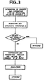
- - la figure 3 est un exemple d'organigramme général de fonctionnement du dispositif suivant l'invention :
- - la figure 4 montre plus en détail un exemple de réalisation de la phase de régulation proprement dite. intervenant dans l'organigramme de la figure 3.
- - Figure 1 is a diagram of a regulating device according to the invention
- - Figures 2a. 2b. 2c. 2d and 2e are examples of curves relating to different types of regulation that can be implemented by the regulation device according to the invention:
- FIG. 3 is an example of a general flowchart of operation of the device according to the invention:
- - Figure 4 shows in more detail an embodiment of the actual regulation phase. involved in the flowchart of figure 3.
Suivant l'exemple décrit sur la figure 1, la régulation d'un moteur 1 est effectué au moyen de trois boucles de régulation permettant lune de téaliser une régulation de puissance, une autre une régulation de vitesse et une autre une régulation de richesse.According to the example described in FIG. 1, the regulation of a motor 1 is carried out by means of three regulation loops allowing one to achieve a power regulation, another a speed regulation and another a richness regulation.
Chacune de ces boucles comporte de manière connue :
- - un organe de commande, permettant à l'opérateur de fixer la valeur de la consigne, respectivement de puissance : 21, de vitesse : 22 et de richesse 23 ;
- - un capteur, respectivement de puissance : 3i, de vitesse : 32, et de richesse : 33 ;
- - un organe de comparaison de la consigne et de la grandeur correspondante mesurée par le capteur, respectivement 41, 42 et 43 ;
- - un actionneur, respectivement de puissance : 61, de vitesse : 62 et de richesse 63, agissant sur les paramètres correspondants du moteur.
- - a control member, allowing the operator to set the setpoint value, respectively of power: 2 1 , of speed: 2 2 and of richness 2 3 ;
- - a sensor, respectively of power: 3i, of speed: 3 2 , and of richness: 3 3 ;
- a member for comparing the setpoint and the corresponding quantity measured by the sensor, respectively 4 1 , 4 2 and 4 3 ;
- - an actuator, respectively of power: 6 1 , of speed: 6 2 and of richness 6 3 , acting on the corresponding parameters of the motor.
Le dispositif suivant l'invention comporte également un régulateur 5 qui est commun à l'ensemble des boucles de régulation et qui permet de réaliser différents types de régulation en tenant compte des interactions entre les différents paramètres.The device according to the invention also comprises a
Ce régulateur 5 reçoit les signaux de sortie des différents organes de comparaison 4i, 42, 43, ainsi que les signaux issus de capteurs 34 et 35 par exemple permettant d'assurer l'acquisition de certains paramètres non régulables par ce dispositif, tels que température et pression, et délivre les signaux d'entrée des différents actionneurs.This
Il est par ailleurs prévu, entre les trois comparateurs 4,, 42 et 43, et le régulateur 5, un ensemble de trois autres comparateurs. respectivement 71, 72, 73. permettant de comparer les paramètres se rapportant à chacune des boucles de régulation, à savoir puissance, vitesse et richesse, à trois valeurs extrêmes appelées respectivement butée de puissance, butée de vitesse et butée de richesse, de façon à assurer le fonctionnement du moteur en deça de ces valeurs extrêmes.There are also provided, between the three comparators 4 ,, 4 2 and 4 3 , and the
Un module 10 réalise les acquisitions des différentes consignes ou commandes, leur traitement et filtrage pour les rendre exploitables par les comparateurs et le régulateur. Des opérations de pondérations respectives des consignes sont également réalisées, et ceci selon les paramètres enregistrés par l'interface homme machine 9.A
L'ensemble formé par ce module 10 par les différents comparateurs et par le régulateur est en tait constitué par un calculateur 8 qui est programmé d'une façon qui sera décrite ulténeurement. en relation avec les figures 3 et 4, pour réaliser différents types de régulation tels que ceux décrits maintenant. à titre d'exemple. en relation avec les figures 2a à 2e. la sélection entre ces différents types de régulation étant effectuée par l'opérateur au moyen d'une interface homme-machine 9 qui communique avec le calculateur 8.The assembly formed by this
Le dispositif suivant l'invention permet, par exemple, la réalisation de régulation de vitesse. de richesse. de puissance, soit de façon indépendante. soit de façon combinée, simultanément ou séparément.The device according to the invention allows, for example, the realization of speed regulation. of wealth. of power, either independently. either in combination, simultaneously or separately.
Dans le cadre de la réalisation de régulations indépendantes, trois cas sont possibles :
- - réalisation d'une régulation de vitesse : le régulateur génère une loi de commande de l'actionneur de vitesse en fonction de la consigne de vitesse. telle que celle représentée à titre d'exemple sur la figure 2a, de façon à assurer une évolution ou un maintien de la vitesse du moteur en liaison avec l'évolution ou le maintien de la consigne de vitesse (par exemple accélérateur), les autres paramètres pouvant amener des corrections.
- - implementation of speed regulation: the regulator generates a speed actuator control law according to the speed setpoint. such as that shown by way of example in FIG. 2a, so as to ensure an evolution or a maintenance of the speed of the motor in connection with the evolution or the maintenance of the speed reference (for example accelerator), the others parameters that can lead to corrections.
La position de l'actionneur vitesse "PAV", peut ainsi s'écrire sous la forme d'une certaine fonction![]()
![]()
![]()
![]()
![]()
![]()
![]()
![]()
![]()
![]()
Dans le cas de régulations combinées mais séparées, par exemple régulation de vitesse et régulation de richesse comme sur la figure 2c. le régulateur met en oeuvre à un instant donnné un seul type de régulation mais ce type de régulation peut évoluer dans le temps, en fonction d'un critère qui est la valeur de la consigne. Par exemple, si la consigne (par exemple la consigne de vitesse) est inférieure à une valeur seuil Cvs, le régulateur assure une régulation de type richesse par exemple, pouvant s'exprimer sous la forme d'une certaine fonction![]()
![]()
![]()
![]()
![]()
![]()
![]()
![]()
![]()
![]()
Dans le cas de régulations combinées, et simultanées (cas de la figure 2e), le régulateur met en oeuvre plusieurs types de régulation à un instant donné (par exemple vitesse, puissance et richesse), pouvant s'exprimer chacune sous la forme d'une certaine fonction de la consigne correspondante et tout ou partie de l'ensemble des autres paramètres, régulables ou non, régulés ou non :In the case of combined and simultaneous regulations (case of Figure 2e), the regulator implements several types of regulation at a given time (for example speed, power and richness), each of which can be expressed in the form of a certain function of the corresponding setpoint and all or part of all of the other parameters, adjustable or not, regulated or not:
Ainsi les différentes expressions :![]()
![]()
![]()
![]()
![]()
![]()
![]()
![]()
![]()
![]()
L'organigramme général de fonctionnement du régulateur est maintenant décrit en relation avec la figure 3. Cet organigramme débute par une introduction de données par l'opérateur : notamment type de régulation souhaitée (à savoir régulations indépendantes, ou combinées, et pour le cas de régulations combinées, séparément ou simultanément, comme défini précédemment), et valeurs des consignes associées. Le régulateur procède ensuite à l'acquisition des différents paramètres du système, par l'intermédiaire des différents capteurs. Le régulateur procède ensuite à un contrôle de la validité des données introduites par l'opérateur. afin de vérifier qu'elles sont bien compatibles avec l'état actuel des différents paramètres du système et n'entraînent pas en particulier de fonctionnement dans une zone critique.The general flowchart of operation of the regulator is now described in relation to FIG. 3. This flowchart begins with the introduction of data by the operator: in particular the type of regulation desired (namely independent, or combined regulations, and for the case of combined regulations, separately or simultaneously, as defined above), and associated setpoint values. The regulator then proceeds to acquire tion of the various parameters of the system, via the various sensors. The regulator then checks the validity of the data entered by the operator. in order to verify that they are indeed compatible with the current state of the various parameters of the system and do not in particular entail operation in a critical zone.
Le calculateur 8 permet par ailleurs d'effectuer une mémorisation systématique des différents paramètres régissant le fonctionnement du moteur. et un contrôle de leur évolution dans le temps assurant ainsi un diagnostic prédictif des pannes.The computer 8 also makes it possible to systematically store the various parameters governing the operation of the engine. and a control of their evolution over time thus ensuring a predictive diagnosis of failures.
Dans le cas où ces données ne sont pas compatibles avec l'état actuel du système, l'opérateur en est averti au moyen de l'interface homme-machine 9. Dans le cas contraire. les informations reçues des capteurs sont comparées aux différentes valeurs de consigne et butées, puis la régulation proprement dite est effectuée, l'opérateur étant tenu informé des valeurs des différents paramètres et de l'état de fonctionnement du système au moyen de l'interface homme-machine 9.In the event that these data are not compatible with the current state of the system, the operator is notified thereof by means of the man-machine interface 9. Otherwise. the information received from the sensors is compared to the different setpoints and stops, then the actual regulation is carried out, the operator being kept informed of the values of the different parameters and of the operating state of the system by means of the human interface - machine 9.
La phase de régulation proprement dite est décrite sous forme d'organigramme à la figure 4. Pour simplifier, cet organigramme correspond aux exemples particuliers de régulation décrits en relation avec les figures 2a à 2e. Suivant le type de régulation choisi (régulations indépendantes. combinées séparément ou combinées simultanément), telles ou telles des formules définies précédemment en relation avec les figures 2a à 2e sont appliquées. avec les valeurs correspondantes des consignes et des paramètres.The actual regulation phase is described in the form of a flowchart in FIG. 4. For simplicity, this flowchart corresponds to the specific examples of regulation described in relation to FIGS. 2a to 2e. Depending on the type of regulation chosen (independent regulations. Combined separately or combined simultaneously), such or such formulas defined above in relation to FIGS. 2a to 2e are applied. with the corresponding values of the setpoints and parameters.
Les différentes fonctions "f" définies précédemment sont prédéterminées en fonction de chaque type de régulation et des caractéristiques du moteur.The different functions "f" defined above are predetermined as a function of each type of regulation and of the characteristics of the engine.
Par ailleurs les différents types de régulation décrits ont été donnés seulement à titre d'exemples. Il existe bien entendu d'autres possibilités. notamment la possibilité de prévoir pour chaque type de régulation différentes fonctions "f" suivant les paramètres Pi sélectionnés par l'opérateur. ou encore la possibilité de réaliser des types de régulation intermédiaires à ceux décrits (par exemple régulations indépendantes sur certains paramètres, régulations combinées sur d'autres paramètres ... etc).Furthermore, the different types of regulation described have been given only by way of examples. There are of course other possibilities. in particular the possibility of providing for each type of regulation different functions "f" according to the parameters Pi selected by the operator. or the possibility of carrying out intermediate types of regulation to those described (for example independent regulations on certain parameters, combined regulations on other parameters ... etc).
Suivant l'exemple de réalisation qui a été décrit, chaque boucle de régulation relative à un paramètre donné comporte un organe d'entrée de consigne, un comparateur, un actionneur et un capteur, tous relatifs au paramètre considéré. Plus généralement. il peut y avoir une interaction entre les différents paramètres, non seulement en ce qui concerne l'élaboration de la loi de régulation de chacun des paramètres, comme on l'a vu précédemment, mais également en ce qui concerne la constitution même de chacune des boucles de régulation. en ce sens que chacune d'elles peut comporter plusieurs organes d'entrée de consigne. plusieurs comparateurs. plusieurs actionneurs et plusieurs comparateurs. relatifs à différents paramètres. ce qui permet de faire évoluer un paramètre donné. suivant la loi de régulation désirée. par action sur différents paramètres. et mesure et comparaison de différents paramètres avec des valeurs de consigne correspondantes.According to the embodiment which has been described, each regulation loop relating to a given parameter comprises a setpoint input member, a comparator, an actuator and a sensor, all relating to the parameter considered. More generally. there can be an interaction between the different parameters, not only with regard to the elaboration of the law of regulation of each of the parameters, as we saw previously, but also with regard to the very constitution of each of the regulation loops. in the sense that each of them can comprise several setpoint input members. several comparators. several actuators and several comparators. related to different parameters. which allows to change a given parameter. according to the desired regulatory law. by action on different parameters. and measurement and comparison of different parameters with corresponding set values.
Le dispositif suivant l'invention permet ainsi d'établir selon des lois de commande optimales. des régulations du type à entrées-sorties monovariables ou multivariables. liées aux paramètres régissant le fonctionnement du moteur.The device according to the invention thus makes it possible to establish according to optimal control laws. monovariable or multivariable input-output type regulations. related to the parameters governing engine operation.
Claims (4)
Applications Claiming Priority (2)
| Application Number | Priority Date | Filing Date | Title |
|---|---|---|---|
| FR8518113 | 1985-12-06 | ||
| FR8518113A FR2591278B1 (en) | 1985-12-06 | 1985-12-06 | COMBUSTION ENGINE CONTROL DEVICE AND METHOD OF USING SUCH A DEVICE. |
Publications (1)
| Publication Number | Publication Date |
|---|---|
| EP0227536A1 true EP0227536A1 (en) | 1987-07-01 |
Family
ID=9325532
Family Applications (1)
| Application Number | Title | Priority Date | Filing Date |
|---|---|---|---|
| EP86402698A Withdrawn EP0227536A1 (en) | 1985-12-06 | 1986-12-05 | Feedback control apparatus for an internal-combustion engine, and method using such an apparatus |
Country Status (4)
| Country | Link |
|---|---|
| US (1) | US4748957A (en) |
| EP (1) | EP0227536A1 (en) |
| JP (1) | JPS62151902A (en) |
| FR (1) | FR2591278B1 (en) |
Families Citing this family (5)
| Publication number | Priority date | Publication date | Assignee | Title |
|---|---|---|---|---|
| JPS63190541U (en) * | 1987-05-27 | 1988-12-08 | ||
| IT1250530B (en) * | 1991-12-13 | 1995-04-08 | Weber Srl | INJECTED FUEL QUANTITY CONTROL SYSTEM FOR AN ELECTRONIC INJECTION SYSTEM. |
| FR2688620B1 (en) * | 1992-03-10 | 1994-10-21 | Thomson Csf | MECHANICAL CONTROL ENERGY TRANSMISSION DEVICE, PARTICULARLY FOR CONTROLLING THE BRAKING PRESSURE IN A BRAKE. |
| JPH07189795A (en) * | 1993-12-28 | 1995-07-28 | Hitachi Ltd | Controller and control method for automobile |
| FR2721413B1 (en) * | 1994-06-21 | 1996-08-30 | Thomson Csf | Hydraulic drawer control device. |
Citations (4)
| Publication number | Priority date | Publication date | Assignee | Title |
|---|---|---|---|---|
| US3750632A (en) * | 1970-03-26 | 1973-08-07 | Bosch Gmbh Robert | Electronic control for the air-fuel mixture and for the ignition of an internal combustion engine |
| GB2064171A (en) * | 1979-11-23 | 1981-06-10 | British Leyland Cars Ltd | Control of Airfuel Ratio in an Automotive Emission Control System |
| US4471741A (en) * | 1982-12-20 | 1984-09-18 | Ford Motor Company | Stabilized throttle control system |
| EP0185552A2 (en) * | 1984-12-19 | 1986-06-25 | Nippondenso Co., Ltd. | Apparatus for controlling operating state of an internal combustion engine |
Family Cites Families (4)
| Publication number | Priority date | Publication date | Assignee | Title |
|---|---|---|---|---|
| US4111178A (en) * | 1976-11-08 | 1978-09-05 | General Motors Corporation | Ignition system for use with fuel injected-spark ignited internal combustion engines |
| US4231331A (en) * | 1977-08-08 | 1980-11-04 | Nissan Motor Company, Limited | Pulse generator of the corona discharge type for sensing engine crankshaft angle on an engine control system |
| JPS57143142A (en) * | 1981-03-02 | 1982-09-04 | Mazda Motor Corp | Controller for engine |
| US4452207A (en) * | 1982-07-19 | 1984-06-05 | The Bendix Corporation | Fuel/air ratio control apparatus for a reciprocating aircraft engine |
-
1985
- 1985-12-06 FR FR8518113A patent/FR2591278B1/en not_active Expired - Fee Related
-
1986
- 1986-12-03 US US06/937,291 patent/US4748957A/en not_active Expired - Fee Related
- 1986-12-05 EP EP86402698A patent/EP0227536A1/en not_active Withdrawn
- 1986-12-06 JP JP61291398A patent/JPS62151902A/en active Pending
Patent Citations (4)
| Publication number | Priority date | Publication date | Assignee | Title |
|---|---|---|---|---|
| US3750632A (en) * | 1970-03-26 | 1973-08-07 | Bosch Gmbh Robert | Electronic control for the air-fuel mixture and for the ignition of an internal combustion engine |
| GB2064171A (en) * | 1979-11-23 | 1981-06-10 | British Leyland Cars Ltd | Control of Airfuel Ratio in an Automotive Emission Control System |
| US4471741A (en) * | 1982-12-20 | 1984-09-18 | Ford Motor Company | Stabilized throttle control system |
| EP0185552A2 (en) * | 1984-12-19 | 1986-06-25 | Nippondenso Co., Ltd. | Apparatus for controlling operating state of an internal combustion engine |
Non-Patent Citations (1)
| Title |
|---|
| IEEE SPECTRUM, vol. 18, no. 5, mai 1981, pages 30-34, IEEE, New York, US; T.O. JONES et al.: "Electronic fuel injection: diesels are next" * |
Also Published As
| Publication number | Publication date |
|---|---|
| US4748957A (en) | 1988-06-07 |
| FR2591278B1 (en) | 1990-01-26 |
| JPS62151902A (en) | 1987-07-06 |
| FR2591278A1 (en) | 1987-06-12 |
Similar Documents
| Publication | Publication Date | Title |
|---|---|---|
| FR2508104A1 (en) | CONTROL DEVICE FOR AN ENGINE OPERATING WITH TWO FUEL GAS / GAS FUEL | |
| FR2794539A1 (en) | CONTROL SYSTEM AND METHOD FOR CONTROLLING AN ENGINE BASED ON DETERIORATION OF THE ENGINE | |
| FR2645208A1 (en) | MARKET CONTROL DEVICE FOR A GAS TURBINE ENGINE | |
| EP0227536A1 (en) | Feedback control apparatus for an internal-combustion engine, and method using such an apparatus | |
| EP1753947B1 (en) | Method for controlling a set torque to be applied to wheels of an automatic transmission for a motor vehicle and corresponding device | |
| EP0184813B1 (en) | Electronic control device for an assembly, consisting of a diesel engine driving a generator, which feeds an electric motor | |
| FR2749040A1 (en) | PROCEDURE FOR ADJUSTING THE PRESSURE IN THE SUCTION DUCT OF AN INTERNAL COMBUSTION ENGINE AND DEVICE FOR IMPLEMENTING THE PROCESS | |
| FR2563278A1 (en) | PROCESS FOR CONTROLLING, ADJUSTING OR CONTROLLING THERMAL TURBO-MACHINES FOLLOWING THE CRITERIA FOR THE SOLICITATION OF MATERIALS | |
| CA2492157C (en) | Gas control apparatus, in particular for turbine engine test bed | |
| EP1753949B1 (en) | Method and device for controlling an automatic transmission for a motor vehicle | |
| FR2532687A1 (en) | ADJUSTING INSTALLATION FOR AN INTERNAL COMBUSTION ENGINE CONTROL STATION | |
| FR2693231A1 (en) | Cooling device for a motor vehicle engine | |
| JP4019710B2 (en) | Engine bench system | |
| WO1991017491A1 (en) | Flow rate adjusting method in an air blowing device and device implementing such method | |
| FR2794509A1 (en) | Friction clutch assisting system for an automobile, utilizes a closed loop control system that uses motor and drive shaft rotation speeds to affect smoother gear changes | |
| EP0500464B1 (en) | Method for digitally controlling electromagnetic means for positioning with active magnetic suspension of a flexible member and apparatus for implementing it | |
| FR2656173A1 (en) | DEVICE FOR CONTROLLING THE OPERATION OF AT LEAST TWO HEAT ENGINES COUPLED ON THE SAME DRIVE SHAFT OF AN ALTERNATOR. | |
| FR2881235A1 (en) | Counter-vibration generator controlling system for motor vehicle, has filter parameter sets, and adjusting unit to collect control signal, giving effective operation of generator, from vibration control sensor to modify parameters of filter | |
| EP1753635B1 (en) | Device and method for controlling torque applied to wheels of a vehicle | |
| FR3074104A1 (en) | PREDICTIVE ADJUSTMENT MOTOR, MOTOR CONTROLLER AND AUTOMATIC MOTOR ADJUSTMENT METHOD | |
| FR2851641A1 (en) | Ventilator regulating method for building, involves determining frequency corresponding to output value and driving ventilator to velocity function of frequency such that intensity of ventilation is adapted to input parameters | |
| FR2773623A1 (en) | METHOD FOR MONITORING THE CONTROL OF AN ADJUSTMENT MEMBER, ESPECIALLY IN A MOTOR VEHICLE | |
| FR2811397A1 (en) | METHOD FOR IMPLEMENTING THE DRIVE UNIT OF A MOTOR VEHICLE AND CONTROL SYSTEM FOR IMPLEMENTING THE METHOD | |
| EP0055146B1 (en) | Frequency-dependent numerical control circuit | |
| EP2032407B1 (en) | Method for regulating the distance between two vehicles |
Legal Events
| Date | Code | Title | Description |
|---|---|---|---|
| PUAI | Public reference made under article 153(3) epc to a published international application that has entered the european phase |
Free format text: ORIGINAL CODE: 0009012 |
|
| AK | Designated contracting states |
Kind code of ref document: A1 Designated state(s): AT BE CH DE ES GB GR IT LI LU NL SE |
|
| 17P | Request for examination filed |
Effective date: 19871217 |
|
| 17Q | First examination report despatched |
Effective date: 19880513 |
|
| STAA | Information on the status of an ep patent application or granted ep patent |
Free format text: STATUS: THE APPLICATION IS DEEMED TO BE WITHDRAWN |
|
| 18D | Application deemed to be withdrawn |
Effective date: 19880924 |
|
| RIN1 | Information on inventor provided before grant (corrected) |
Inventor name: MENARD, CHRISTIAN Inventor name: MEULEMAN, JEAN-JACQUES Inventor name: MAROUBY, DANIEL Inventor name: FAOUEN, ERIC |