EP0226499B1 - Aménagement interne anti-clappement pour propulseur à poudre et son procédé de fabrication - Google Patents
Aménagement interne anti-clappement pour propulseur à poudre et son procédé de fabrication Download PDFInfo
- Publication number
- EP0226499B1 EP0226499B1 EP86402573A EP86402573A EP0226499B1 EP 0226499 B1 EP0226499 B1 EP 0226499B1 EP 86402573 A EP86402573 A EP 86402573A EP 86402573 A EP86402573 A EP 86402573A EP 0226499 B1 EP0226499 B1 EP 0226499B1
- Authority
- EP
- European Patent Office
- Prior art keywords
- teeth
- heat
- protection layer
- skin
- mask
- Prior art date
- Legal status (The legal status is an assumption and is not a legal conclusion. Google has not performed a legal analysis and makes no representation as to the accuracy of the status listed.)
- Expired
Links
- 238000000034 method Methods 0.000 title claims description 13
- 238000004519 manufacturing process Methods 0.000 title description 9
- 239000003380 propellant Substances 0.000 claims description 25
- 238000000926 separation method Methods 0.000 claims description 18
- 238000002485 combustion reaction Methods 0.000 claims description 10
- 239000007789 gas Substances 0.000 claims description 7
- 239000000463 material Substances 0.000 claims 9
- 230000015572 biosynthetic process Effects 0.000 claims 3
- 239000004449 solid propellant Substances 0.000 claims 2
- 238000000465 moulding Methods 0.000 claims 1
- 239000007787 solid Substances 0.000 claims 1
- 239000000843 powder Substances 0.000 description 12
- 238000000576 coating method Methods 0.000 description 8
- 229920001343 polytetrafluoroethylene Polymers 0.000 description 8
- 239000004810 polytetrafluoroethylene Substances 0.000 description 8
- 239000011248 coating agent Substances 0.000 description 7
- 239000011253 protective coating Substances 0.000 description 4
- 238000004073 vulcanization Methods 0.000 description 4
- 230000001681 protective effect Effects 0.000 description 3
- 230000001133 acceleration Effects 0.000 description 1
- 239000000567 combustion gas Substances 0.000 description 1
- 230000000694 effects Effects 0.000 description 1
- 239000008188 pellet Substances 0.000 description 1
- -1 polytetrafluoroethylene Polymers 0.000 description 1
- 230000002035 prolonged effect Effects 0.000 description 1
- 230000001737 promoting effect Effects 0.000 description 1
- 230000035939 shock Effects 0.000 description 1
- 239000004636 vulcanized rubber Substances 0.000 description 1
Images


Classifications
-
- F—MECHANICAL ENGINEERING; LIGHTING; HEATING; WEAPONS; BLASTING
- F02—COMBUSTION ENGINES; HOT-GAS OR COMBUSTION-PRODUCT ENGINE PLANTS
- F02K—JET-PROPULSION PLANTS
- F02K9/00—Rocket-engine plants, i.e. plants carrying both fuel and oxidant therefor; Control thereof
- F02K9/08—Rocket-engine plants, i.e. plants carrying both fuel and oxidant therefor; Control thereof using solid propellants
- F02K9/32—Constructional parts; Details not otherwise provided for
- F02K9/36—Propellant charge supports
-
- F—MECHANICAL ENGINEERING; LIGHTING; HEATING; WEAPONS; BLASTING
- F02—COMBUSTION ENGINES; HOT-GAS OR COMBUSTION-PRODUCT ENGINE PLANTS
- F02K—JET-PROPULSION PLANTS
- F02K9/00—Rocket-engine plants, i.e. plants carrying both fuel and oxidant therefor; Control thereof
- F02K9/08—Rocket-engine plants, i.e. plants carrying both fuel and oxidant therefor; Control thereof using solid propellants
- F02K9/32—Constructional parts; Details not otherwise provided for
- F02K9/34—Casings; Combustion chambers; Liners thereof
- F02K9/346—Liners, e.g. inhibitors
Definitions
- the present invention relates to an internal anti-clapper arrangement for a powder propellant of the type comprising a powder block housed in an envelope with the interposition of a thermal protection and delimiting a combustion chamber, a separation formed between the powder block and the coating. for thermal protection of the bottom structure of the propellant by means of a skin detached from said coating and adhering to the block of powder, and means providing a passage for the gases from the combustion chamber in the separation.
- a propellant of the type defined above is described in French patent No 2 466 627.
- the powder blocks for propellants are stressed by mechanical forces and deformations, in particular elongations, during the manufacturing, storage and operating phases.
- the volume occupied by the separations is variable depending on the position of the propellant, state conditions and the forces acting on the propellant. It may even happen that one or more detachments are closed as a result for example of prolonged storage, a field of accelerations, internal pressure acting on the bottom, unforeseen adhesion of the faces with regard to the separation, ...
- the invention also relates to a method of manufacturing such a propellant arrangement, according to claim 4.
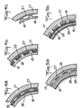
- FIG. 1 schematically shows a powder propellant comprising an envelope 10 and a powder block 11 housed in the envelope with the interposition of a thermal protection 12.
- a central channel forming combustion chamber 13 is formed in the powder block.
- detachments 15, 20 are formed by skins 16, 21 detached from the coatings 17, 22 for thermal protection of the bottom structures of the propellant.
- the coverings 17, 22 have a thickness greater than that of the thermal protection in the central region of the propellant, in particular on the rear side where a nozzle 14 is fixed. In fact, during the consumption of the block powder, these are the bottom areas which are the first in contact with the combustion gases.
- protuberances or spikes are formed in the separations 15, 20 to prevent them from closing and to promote the passage of gases from the combustion chamber to the separations after ignition.
- the pins 18 are, in the example illustrated, formed in one piece with the peeled skin 16, in a staggered arrangement.
- the pins can also be formed on the thermal protective coating of the bottom structure, like the pins 23 in FIG. 1.
- the pins have for example a shape of circular pellets.
- Figures 4a to 4c illustrate a method of manufacturing the peeled skin 16 with pins 18 shown in Figure 2.
- the peeled skin 16 of unvulcanized rubber is draped over the thermal protective coating 17 previously vulcanized, with the interposition of a mask with pins 25 (fig 4a).
- the latter consists of a perforated sheet of vulcanized rubber, the thickness of which is equal to that of the pins to be produced and the perforations of which are arranged in the desired locations for the pins.
- the sheet 25 can be produced by draping and then vulcanization using the thermal protective coating 17 as a mold; it is then perforated.
- Sheets 26, 27 of polytetrafluoroethylene (PTFE) are arranged on each side of the mask with studs 25 to prevent sticking of the rubber of the peeled-off skin on the mask or, through the latter, on the coating 17 during the v ⁇ lca- nization.
- the assembly thus formed is subjected to vulcanization. Under the effect of the pressure, the rubber flows in the holes of the mask 25 by deforming the PTFE film 26.
- the internal face of the detached skin 16 offers a smooth and continuous profile while the external face has pins 18 at the locations of the mask 25 perforations. The latter is then removed and only one 27 of the sheets 26, 27 is left in place to prevent any possible sticking of the pins 18 on the thermal protection 17 (fig.4c).
- the pins 18 can be formed on the thermal protection as illustrated by FIGS. 5a and 5b.
- the peeled-off skin 16 is first produced on a male mold 28.
- the unvulcanized thermal protection 17 is then draped over this mold equipped with the vulcanized peeled-off skin 16 with the interposition of the studded mask 25 and PT-FE sheets 26, 27 on each side of the mask (fig 5a).
- the thermal protection is vulcanized, which causes the rubber to creep into the mask holes 25 with deformation of the sheet 27 (FIG. 5b).
- the mask with pins 25 is removed as well as one 27 from the sheets 26, 27, leaving the covering 17 provided with pins 18 at the locations occupied by the perforations of the mask 25.
- the thermal protective coating 17 is formed directly with pins 18 in a mold having a corresponding profile (FIG. 6a). Then, the detached skin 16 is draped over the thermal protection 17, after fitting a mask with pins 25, to fill the spaces between the pins 18 in order to prevent them from imprinting in the skin detached, and after interposition of a sheet 26 of PTFE to avoid sticking of the skin 16 on the pins 18 (fig 6b). The peeled skin is vulcanized and the mask is removed.
- the detached skin and thermal protection coating assembly can be formed in a single operation.
- the thermal protection 17 is draped and is covered with a PTFE sheet 30, a vulcanized protective skin 29, possibly with a PTFE sheet 27, a mask with pins 25, and a second sheet of PTFE 26 on which the peeled skin is draped 16.
- the thermal protection and the peeled skin are vulcanized.
- the rubber of the peeled off skin creeps into the perforations of the mask to form the pins 18 while the creep of the rubber of the thermal protection is prevented by the protective skin 29.
- the pins could similarly be formed on the thermal protection coating by reversing the positions of the mask 25 and the protective skin 29.
Landscapes
- Engineering & Computer Science (AREA)
- Chemical & Material Sciences (AREA)
- Combustion & Propulsion (AREA)
- Mechanical Engineering (AREA)
- General Engineering & Computer Science (AREA)
- Laminated Bodies (AREA)
Description
- La présente invention concerne un aménagement interne anti-clappement pour propulseur à poudre du type comprenant un bloc de poudre logé dans une enveloppe avec interposition d'une protection thermique et délimitant une chambre de combustion, un décollement formé entre le bloc de poudre et le revêtement de protection thermique de la structure de fond du propulseur au moyen d'une peau décollée dudit revêtement et adhérant au bloc de poudre, et des moyens ménageant un passage pour les gaz de la chambre de combustion dans le décollement.
- Un propulseur du type défini ci-dessus est décrit dans le brevet française No 2 466 627. Les blocs de poudre pour propulseurs sont sollicités par des efforts et déformations mécaniques, notamment des allongements, lors des phases de fabrication, de stockage et de fonctionnement. Aussi, il est bien connu de ménager des zones de séparation ou décollements entre le bloc de poudre et la structure voisine du propulseur, notamment dans les zones de fond. Le volume occupé par les décollements est variable en fonction de la position du propulseur, de conditions d'état et des efforts agissant sur le propulseur. Il peut même se produire qu'un ou plusieurs décollements soient fermés par suite par exemple d'un stockage prolongé, d'un champ d'accélérations, d'une pression interne s'exerçant sur le fond, d'une adhérence imprévue des faces en regard du décollement,... Dans un tel cas, une ouverture brutale du décollement après l'allumage du propulseur peut provoquer une variation brusque de l'effort exercé sur le bloc de poudre tout le long du décollement. Le choc ainsi produit, ou "clappement", peut avoir une intensité élevée et mettre en danger la tenue des équipements véhiculés par le propulseur. Pour prévenir le phénomène de clappement, il a été proposé dans le brevet français No 2 466 627 précité de former un passage faisant communiquer la chambre de combustion avec le décollement au moyen d'éléments liés à la structure de fond du propulseur et au bloc de poudre, ces éléments étant agencés pour maintenir sensiblement constante la section du passage lors de mouvements de fermeture ou d'ouverture du décollement.
- Toutefois, les solutions décrites dans le brevet français No 2 466 627 résultent en une structure du propulseur relativement complexe et la présente invention a pour but de fournir un moyen de favoriser le passage des gaz de la chambre de combustion vers le décollement, sans complication de la structure du propulseur et de sa fabrication.
- Ce but est atteint au moyen d'un aménagement de propulseur selon la revendication 1. L'invention a également pour objet un procédé de fabrication d'un tel aménagement de propulseur, selon la revendication 4.
- D'autres particularités et avantages de l'invention ressortiront à la lecture de la description faite ci-après à titre indicatif mais non limitatif en référence aux dessins annexés sur lesquels :
- - la figure 1 est une vue générale d'un propulseur présentant un aménagement interne anti-clappement conforme à l'invention,
- - la figure 2 est une vue de détail d'une partie de fond du propulseur de la figure 1,
- - la figure 3 est une vue partielle montrant l'agencement des picots sur la peau décollée de la figure 2,
- - les figures 4a à 4ç illustrent des phases d'un procédé de fabrication de la peau décollée à picots de la figure 2, et
- - les figures 5a - 5b, 6a - 6b et 7 illustrent d'autres modes de fabrication de picots pour une structure de propulseur selon l'invention.
- La figure 1 montre schématiquement un propulseur à poudre comprenant une enveloppe 10 et un bloc de poudre 11 logé dans l'enveloppe avec interposition d'une protection thermique 12. Un canal central formant chambre de combustion 13 est ménagé dans le bloc de poudre. Aux extrémités du propulseur, des décollements 15, 20 sont formés par des peaux 16, 21 décollées des revêtements 17, 22 de protection thermique des structures de fond du propulseur. Comme le montre la figure 1, les revêtements 17, 22 présentent une épaisseur supérieure à celle de la protection thermique dans la zone centrale du propulseur, notamment du côté arrière où est fixée une tuyère 14. En effet, au cours de la consommation du bloc de poudre, ce sont les zones de fond qui sont les premières en contact avec les gaz de combustion.
- Conformément à l'invention, des protubérances ou picots sont formés dans les décollements 15, 20 pour éviter la fermeture de ceux-ci et favoriser le passage des gaz de la chambre de combustion vers les décollements après allumage.
- Comme le montrent la figure 1 et, de façon plus détaillée, les figures 2 et 3, les picots 18 sont, dans l'exemple illustré, formés d'une seule pièce avec la peau décollée 16, suivant une disposition en quinconce. Bien entendu, les picots peuvent également être formés sur le revêtement de protection thermique de la structure de fond, comme les picots 23 de la figure 1. Les picots ont par exemple une forme de pastilles circulaires.
- Les figures 4a à 4c illustrent un mode de fabrication de la peau décollée 16 à picots 18 montrée sur la figure 2. La peau décollée 16 en caoutchouc non vulcanisé est drapée sur le revêtement de protection thermique 17 préalablement vulcanisé, avec interposition d'un masque à picots 25 (fig 4a). Ce dernier est constitué par une feuille perforée en caoutchouc vulcanisé dont l'épaisseur est égale à celle des picots à réaliser et dont les perforations sont disposées selon les emplacements désirés pour les picots. La feuille 25 peut être réalisée par drapage puis vulcanisation en utilisant comme moule le revêtement de protection thermique 17 ; elle est ensuite perforée. Des feuilles 26, 27 de polytétrafluoroé- thylène (PTFE) sont disposées de chaque côté du masque à picots 25 pour éviter le collage du caoutchouc de la peau décollée sur le masque ou, à travers celui-ci, sur le revêtement 17 lors de la vÚlca- nisation. L'ensemble ainsi constitué est soumis à une vulcanisation. Sous l'effet de la pression, le caoutchouc flue dans les trous du masque 25 en déformant le film 26 de PTFE. Après vulcanisation (fig 4b), la face interne de la peau décollée 16 offre un profil lisse et continu tandis que la face externe présente des picots 18 aux emplacements des perforations du masque 25. Ce dernier est ensuite retiré et une seule 27 des feuilles 26, 27 est laissée en place pour empêcher tout collage éventuel des picots 18 sur la protection thermique 17 (fig.4c).
- En variante, les picots 18 peuvent être formés sur la protection thermique comme illustré par les figures 5a et 5b. La peau décollée 16 est d'abord réalisée sur un moule mâle 28. La protection thermique 17 non vulcanisée est ensuite drapée sur ce moule équipé de la peau décollée vulcanisée 16 avec interposition du masque à picots 25 et des feuilles de PT-FE 26, 27 de chaque côté du masque (fig 5a). La protection thermique est vulcanisée ce qui provoque un fluage du caoutchouc dans les trous de masque 25 avec déformation de la feuille 27 (fig. 5b). Après vulcanisation, le masque à picots 25 est retiré ainsi que l'une 27 des feuilles 26, 27, laissant le revêtement 17 muni de picots 18 aux emplacements occupés par les perforations du masque 25.
- Selon encore une autre variante le revêtement de protection thermique 17 est formé directement avec des picots 18 dans un moule ayant un profil correspondant (fig 6a). Ensuite, la peau décollée 16 est drapée sur la protection thermique 17, après mise en place d'un masque à picots 25, pour combler les espaces entre les picots 18 afin d'éviter qu'ils s'impriment dans la peau décollée, et après interposition d'une feuille 26 de PTFE pour éviter le collage de la peau 16 sur les picots 18 (fig 6b). La peau décollée est vulcanisée puis le masque est retiré. Bien entendu, on pourrait de façon similaire former directement la peau décollée avec des picots dans un moule ayant un profil correspondant, puis draper le revêtement de protection thermique après interposition du masque à picots et d'une feuille de PTFE, et vulcaniser le revêtement.
- Enfin, selon encore une autre variante (fig 7), l'ensemble peau décollée et revêtement de protection thermique peut être formé en une seule opération. La protection thermique 17 est drapée et est re- couverte d'une feuille de PTFE 30, d'une peau de protection vulcanisée 29, éventuellement d'une feuille de PTFE 27, de masque à picots 25, et d'une deuxième feuille de PTFE 26 sur laquelle est drapée la peau décollée 16. La protection thermique et la peau décollée sont vulcanisées. Le caoutchouc de la peau décollée flue dans les perforations du masque pour former les picots 18 tandis que le fluage du caoutchouc de la protection thermique est empêché par la peau de protection 29. Bien entendu, les picots pourraient de la même façon être formés sur le revêtement de protection thermique en inversant les positions du masque 25 et de la peau de protection 29.
Claims (8)
Applications Claiming Priority (2)
| Application Number | Priority Date | Filing Date | Title |
|---|---|---|---|
| FR8518021 | 1985-12-05 | ||
| FR8518021A FR2591281B1 (fr) | 1985-12-05 | 1985-12-05 | Amenagement interne anti-clappement pour propulseur a poudre et son procede de fabrication. |
Publications (2)
| Publication Number | Publication Date |
|---|---|
| EP0226499A1 EP0226499A1 (fr) | 1987-06-24 |
| EP0226499B1 true EP0226499B1 (fr) | 1989-11-08 |
Family
ID=9325484
Family Applications (1)
| Application Number | Title | Priority Date | Filing Date |
|---|---|---|---|
| EP86402573A Expired EP0226499B1 (fr) | 1985-12-05 | 1986-11-20 | Aménagement interne anti-clappement pour propulseur à poudre et son procédé de fabrication |
Country Status (4)
| Country | Link |
|---|---|
| US (2) | US4803038A (fr) |
| EP (1) | EP0226499B1 (fr) |
| DE (1) | DE3666858D1 (fr) |
| FR (1) | FR2591281B1 (fr) |
Families Citing this family (17)
| Publication number | Priority date | Publication date | Assignee | Title |
|---|---|---|---|---|
| JP3136060B2 (ja) | 1994-12-08 | 2001-02-19 | 株式会社アイ・エイチ・アイ・エアロスペース | 固体ロケットモータ |
| RU2117811C1 (ru) * | 1996-11-21 | 1998-08-20 | Акционерное общество "Станкомаш" | Способ защиты внутренней поверхности корпуса ракетного двигателя |
| RU2163686C1 (ru) * | 1999-07-21 | 2001-02-27 | Государственное унитарное предприятие "Государственное научно-производственное предприятие "Сплав" | Ракетный двигатель твердого топлива |
| RU2164617C1 (ru) * | 1999-08-09 | 2001-03-27 | Научно-исследовательский институт полимерных материалов | Газогенератор |
| RU2174619C1 (ru) * | 2000-11-09 | 2001-10-10 | Федеральный центр двойных технологий "Союз" | Корпус ракетного двигателя твердого топлива типа "кокон" |
| RU2218472C1 (ru) * | 2003-02-06 | 2003-12-10 | Открытое акционерное общество Федеральный научно-производственный центр "Станкомаш" | Корпус ракетного двигателя твердого топлива |
| RU2245450C1 (ru) * | 2003-06-24 | 2005-01-27 | Федеральное государственное унитарное предприятие "Научно-исследовательский институт полимерных материалов" | Ракетный двигатель твёрдого ракетного топлива |
| RU2302546C2 (ru) * | 2005-08-10 | 2007-07-10 | Открытое акционерное общество Научно-производственное объединение "Искра" | Корпус ракетного двигателя твердого топлива |
| RU2317664C1 (ru) * | 2005-12-02 | 2011-06-20 | ФГУП "КБточмаш им. А.Э.Нудельмана" | Ракетный двигатель твердого топлива |
| RU2312999C1 (ru) * | 2006-05-02 | 2007-12-20 | Государственное образовательное учреждение высшего профессионального образования "Пермский государственный технический университет" | Ракетный двигатель на твердом топливе |
| RU2498101C2 (ru) * | 2011-12-05 | 2013-11-10 | Открытое акционерное общество Научно-производственное объединение "Искра" | Снаряженный корпус ракетного двигателя твердого топлива |
| RU2493402C1 (ru) * | 2012-04-10 | 2013-09-20 | Открытое акционерное общество "Научно-исследовательский институт полимерных материалов" | Заряд смесевого твердого топлива |
| RU2528194C1 (ru) * | 2013-06-14 | 2014-09-10 | Открытое акционерное общество Центральный научно-исследовательский институт специального машиностроения | Корпус ракетного двигателя твердого топлива (варианты) и способ его изготовления (варианты) |
| JP6680570B2 (ja) * | 2016-03-04 | 2020-04-15 | 株式会社Ihiエアロスペース | ロケットモータのインシュレータの製造方法 |
| IT201700115681A1 (it) * | 2017-10-13 | 2019-04-13 | Avio Spa | Procedimento di collaudo per collaudare un motore a propellente solido, e motore a propellente solido per attuare tale procedimento |
| RU2727222C1 (ru) * | 2020-01-27 | 2020-07-21 | Акционерное общество "Корпорация "Московский институт теплотехники" (АО "Корпорация "МИТ") | Стартовый твердотопливный ускоритель ракеты-носителя |
| CN114941584B (zh) * | 2022-04-28 | 2025-09-30 | 湖北航天技术研究院总体设计所 | 适用于固体姿控发动机压强波动的绝热结构及燃发器 |
Family Cites Families (11)
| Publication number | Priority date | Publication date | Assignee | Title |
|---|---|---|---|---|
| GB729525A (en) * | 1953-04-11 | 1955-05-04 | Mini Of Supply | Improvements in or relating to solid propellant jet reaction motors |
| US2957309A (en) * | 1957-07-22 | 1960-10-25 | Phillips Petroleum Co | Rocket motor |
| US3364809A (en) * | 1965-07-26 | 1968-01-23 | North American Aviation Inc | Method of assembling a solid propellant grain |
| US3362159A (en) * | 1966-07-19 | 1968-01-09 | Thiokol Chemical Corp | Stress relief arrangement for solid propellant rocket motors |
| US3446018A (en) * | 1966-12-08 | 1969-05-27 | Thiokol Chemical Corp | Liner for solid propellant rocket motor |
| US3616646A (en) * | 1970-03-24 | 1971-11-02 | Us Air Force | Forward or aft stress relief for a case bonded solid propellant |
| US3786633A (en) * | 1973-01-26 | 1974-01-22 | Us Navy | Propellant immobilizer and resonance suppression system |
| JPS533445B2 (fr) * | 1973-10-17 | 1978-02-07 | ||
| FR2466627A1 (fr) * | 1979-10-05 | 1981-04-10 | Europ Propulsion | Dispositif anti-clappement pour propulseur a propergol solide |
| US4345427A (en) * | 1979-10-26 | 1982-08-24 | Thiokol Corporation | Rocket motor or gas generator having controlled thrust or mass flow output |
| US4458483A (en) * | 1982-10-21 | 1984-07-10 | United States Of America As Represented By The Secretary Of The Navy | Rocket motor end flap |
-
1985
- 1985-12-05 FR FR8518021A patent/FR2591281B1/fr not_active Expired
-
1986
- 1986-11-20 DE DE8686402573T patent/DE3666858D1/de not_active Expired
- 1986-11-20 EP EP86402573A patent/EP0226499B1/fr not_active Expired
-
1988
- 1988-01-21 US US07/146,385 patent/US4803038A/en not_active Expired - Lifetime
- 1988-09-06 US US07/247,436 patent/US4823548A/en not_active Expired - Lifetime
Also Published As
| Publication number | Publication date |
|---|---|
| US4823548A (en) | 1989-04-25 |
| US4803038A (en) | 1989-02-07 |
| EP0226499A1 (fr) | 1987-06-24 |
| FR2591281A1 (fr) | 1987-06-12 |
| FR2591281B1 (fr) | 1988-04-01 |
| DE3666858D1 (en) | 1989-12-14 |
Similar Documents
| Publication | Publication Date | Title |
|---|---|---|
| EP0226499A1 (fr) | Aménagement interne anti-clappement pour propulseur à poudre et son procédé de fabrication | |
| EP0368734B1 (fr) | Outillage pour le moulage de panneaux auto-raidis en matériau composite | |
| EP0584017B1 (fr) | Presse pour le formage d'une pièce en matériau composite comportant des renforts fibreux dans une matrice en polymère | |
| FR2559423A1 (fr) | Elements a profil de pale creux composites et leur procede de fabrication | |
| EP2183121B1 (fr) | Pneumatique equipe pour la fixation d'un objet a sa paroi et son procede de fabrication | |
| EP0213998B1 (fr) | Bagues d'étanchéité de type radial et procédé de réalisation de telles bagues | |
| WO2002038355A1 (fr) | Moules pour la transformation des matieres plastiques et composites et procede de transformation associe | |
| EP0650620A1 (fr) | Procede de fabrication d'une carte comprenant au moins un element electronique et carte obtenue par un tel procede. | |
| FR2943268A1 (fr) | Moule de thermofromage a isolation thermique et procede associe. | |
| EP2382073B1 (fr) | Dispositif de fabrication d'une pièce en matériau composite par moulage par transfert de résine | |
| EP1034908B1 (fr) | Element moulant pour moule de bande de roulement de pneumatique | |
| FR2650217A1 (fr) | Procede et dispositif de revetement de protection thermique interne de propulseur | |
| EP3442766A1 (fr) | Procede et moule pour la realisation d'un element aerodynamique comportant des riblets | |
| EP0290481A1 (fr) | Procede de fabrication d'une coquille thermoisolante a stabilite de forme | |
| EP0451042A1 (fr) | Moule pour le moulage de pièces en matière plastique, et son procédé de fabrication | |
| EP1226923B1 (fr) | Pièce mécanique en forme de feuille en élastomère renforcée, son procédé de fabrication et moule pour ladite fabrication | |
| FR2704280A1 (fr) | Système de suppression des contraintes dans un moteur-fusée à combustible solide. | |
| FR3073000A1 (fr) | Aube mobile d'une turbomachine | |
| EP3393776A1 (fr) | Moule de vulcanisation avec une etancheite renforcee | |
| FR3068914A1 (fr) | Procede de fabrication d'un bandage pneumatique avec une bande de roulement perfectionnee | |
| EP3921208A1 (fr) | Ecran de protection acoustique pour compartiment à moteur de véhicule automobile | |
| EP1305157B1 (fr) | Procede de fabrication d'une chenille et dispositif de demoulage | |
| EP1127517A1 (fr) | Procédé de fabrication d'un revêtement anti-lacération pour siège | |
| MC1469A1 (fr) | Procede de reproduction de formes et de finis par enroulement de filaments impregnes de matiere plastique dans un moule comportant une feuille de demoulage | |
| FR2515736A1 (fr) | Procede de fabrication d'un chargement de propergol et charge propulsive comprenant un tel chargement |
Legal Events
| Date | Code | Title | Description |
|---|---|---|---|
| PUAI | Public reference made under article 153(3) epc to a published international application that has entered the european phase |
Free format text: ORIGINAL CODE: 0009012 |
|
| AK | Designated contracting states |
Kind code of ref document: A1 Designated state(s): DE GB IT |
|
| 17P | Request for examination filed |
Effective date: 19871112 |
|
| 17Q | First examination report despatched |
Effective date: 19880801 |
|
| ITF | It: translation for a ep patent filed | ||
| GRAA | (expected) grant |
Free format text: ORIGINAL CODE: 0009210 |
|
| AK | Designated contracting states |
Kind code of ref document: B1 Designated state(s): DE GB IT |
|
| REF | Corresponds to: |
Ref document number: 3666858 Country of ref document: DE Date of ref document: 19891214 |
|
| GBT | Gb: translation of ep patent filed (gb section 77(6)(a)/1977) | ||
| PLBE | No opposition filed within time limit |
Free format text: ORIGINAL CODE: 0009261 |
|
| STAA | Information on the status of an ep patent application or granted ep patent |
Free format text: STATUS: NO OPPOSITION FILED WITHIN TIME LIMIT |
|
| 26N | No opposition filed | ||
| ITTA | It: last paid annual fee | ||
| REG | Reference to a national code |
Ref country code: GB Ref legal event code: 732E |
|
| REG | Reference to a national code |
Ref country code: GB Ref legal event code: IF02 |
|
| PGFP | Annual fee paid to national office [announced via postgrant information from national office to epo] |
Ref country code: DE Payment date: 20031107 Year of fee payment: 18 |
|
| PGFP | Annual fee paid to national office [announced via postgrant information from national office to epo] |
Ref country code: GB Payment date: 20031114 Year of fee payment: 18 |
|
| PG25 | Lapsed in a contracting state [announced via postgrant information from national office to epo] |
Ref country code: GB Free format text: LAPSE BECAUSE OF NON-PAYMENT OF DUE FEES Effective date: 20041120 |
|
| PG25 | Lapsed in a contracting state [announced via postgrant information from national office to epo] |
Ref country code: DE Free format text: LAPSE BECAUSE OF NON-PAYMENT OF DUE FEES Effective date: 20050601 |
|
| GBPC | Gb: european patent ceased through non-payment of renewal fee |
Effective date: 20041120 |
|
| PG25 | Lapsed in a contracting state [announced via postgrant information from national office to epo] |
Ref country code: IT Free format text: LAPSE BECAUSE OF NON-PAYMENT OF DUE FEES Effective date: 20051120 |