EP0226343B1 - Microwave oven - Google Patents
Microwave oven Download PDFInfo
- Publication number
- EP0226343B1 EP0226343B1 EP86309005A EP86309005A EP0226343B1 EP 0226343 B1 EP0226343 B1 EP 0226343B1 EP 86309005 A EP86309005 A EP 86309005A EP 86309005 A EP86309005 A EP 86309005A EP 0226343 B1 EP0226343 B1 EP 0226343B1
- Authority
- EP
- European Patent Office
- Prior art keywords
- lamp
- microwave
- lamps
- infra
- unit
- Prior art date
- Legal status (The legal status is an assumption and is not a legal conclusion. Google has not performed a legal analysis and makes no representation as to the accuracy of the status listed.)
- Expired - Lifetime
Links
- 229910052736 halogen Inorganic materials 0.000 claims description 16
- 230000005855 radiation Effects 0.000 claims description 11
- 150000002367 halogens Chemical class 0.000 claims description 9
- IJGRMHOSHXDMSA-UHFFFAOYSA-N Atomic nitrogen Chemical compound N#N IJGRMHOSHXDMSA-UHFFFAOYSA-N 0.000 claims description 8
- 230000015572 biosynthetic process Effects 0.000 claims description 6
- 230000002401 inhibitory effect Effects 0.000 claims description 6
- 239000000654 additive Substances 0.000 claims description 5
- 230000000996 additive effect Effects 0.000 claims description 5
- WFKWXMTUELFFGS-UHFFFAOYSA-N tungsten Chemical compound [W] WFKWXMTUELFFGS-UHFFFAOYSA-N 0.000 claims description 5
- 229910052721 tungsten Inorganic materials 0.000 claims description 5
- 239000010937 tungsten Substances 0.000 claims description 5
- 229910052757 nitrogen Inorganic materials 0.000 claims description 4
- 239000007789 gas Substances 0.000 claims description 3
- 239000000919 ceramic Substances 0.000 description 6
- 230000004048 modification Effects 0.000 description 6
- 238000012986 modification Methods 0.000 description 6
- 238000013021 overheating Methods 0.000 description 6
- XKRFYHLGVUSROY-UHFFFAOYSA-N Argon Chemical compound [Ar] XKRFYHLGVUSROY-UHFFFAOYSA-N 0.000 description 4
- 230000005540 biological transmission Effects 0.000 description 3
- 239000000463 material Substances 0.000 description 3
- 230000001681 protective effect Effects 0.000 description 3
- 239000010453 quartz Substances 0.000 description 3
- 230000001172 regenerating effect Effects 0.000 description 3
- VYPSYNLAJGMNEJ-UHFFFAOYSA-N silicon dioxide Inorganic materials O=[Si]=O VYPSYNLAJGMNEJ-UHFFFAOYSA-N 0.000 description 3
- 229910052786 argon Inorganic materials 0.000 description 2
- 238000010276 construction Methods 0.000 description 2
- 230000000694 effects Effects 0.000 description 2
- 239000000835 fiber Substances 0.000 description 2
- 229910052751 metal Inorganic materials 0.000 description 2
- 239000002184 metal Substances 0.000 description 2
- 229910000859 α-Fe Inorganic materials 0.000 description 2
- 101000793686 Homo sapiens Azurocidin Proteins 0.000 description 1
- ZOKXTWBITQBERF-UHFFFAOYSA-N Molybdenum Chemical compound [Mo] ZOKXTWBITQBERF-UHFFFAOYSA-N 0.000 description 1
- 206010047571 Visual impairment Diseases 0.000 description 1
- 230000002745 absorbent Effects 0.000 description 1
- 239000002250 absorbent Substances 0.000 description 1
- 239000011324 bead Substances 0.000 description 1
- 229910010293 ceramic material Inorganic materials 0.000 description 1
- 238000010411 cooking Methods 0.000 description 1
- 238000001816 cooling Methods 0.000 description 1
- 239000011888 foil Substances 0.000 description 1
- 239000002241 glass-ceramic Substances 0.000 description 1
- 238000010438 heat treatment Methods 0.000 description 1
- 239000011261 inert gas Substances 0.000 description 1
- 238000009413 insulation Methods 0.000 description 1
- 229910052750 molybdenum Inorganic materials 0.000 description 1
- 239000011733 molybdenum Substances 0.000 description 1
- 239000002245 particle Substances 0.000 description 1
- 238000005192 partition Methods 0.000 description 1
- 230000001902 propagating effect Effects 0.000 description 1
- 230000002829 reductive effect Effects 0.000 description 1
- 230000000717 retained effect Effects 0.000 description 1
- 229910001220 stainless steel Inorganic materials 0.000 description 1
- 239000010935 stainless steel Substances 0.000 description 1
Images


Classifications
-
- H—ELECTRICITY
- H05—ELECTRIC TECHNIQUES NOT OTHERWISE PROVIDED FOR
- H05B—ELECTRIC HEATING; ELECTRIC LIGHT SOURCES NOT OTHERWISE PROVIDED FOR; CIRCUIT ARRANGEMENTS FOR ELECTRIC LIGHT SOURCES, IN GENERAL
- H05B6/00—Heating by electric, magnetic or electromagnetic fields
- H05B6/64—Heating using microwaves
- H05B6/66—Circuits
- H05B6/666—Safety circuits
-
- H—ELECTRICITY
- H05—ELECTRIC TECHNIQUES NOT OTHERWISE PROVIDED FOR
- H05B—ELECTRIC HEATING; ELECTRIC LIGHT SOURCES NOT OTHERWISE PROVIDED FOR; CIRCUIT ARRANGEMENTS FOR ELECTRIC LIGHT SOURCES, IN GENERAL
- H05B6/00—Heating by electric, magnetic or electromagnetic fields
- H05B6/64—Heating using microwaves
- H05B6/647—Aspects related to microwave heating combined with other heating techniques
- H05B6/6482—Aspects related to microwave heating combined with other heating techniques combined with radiant heating, e.g. infrared heating
-
- H—ELECTRICITY
- H05—ELECTRIC TECHNIQUES NOT OTHERWISE PROVIDED FOR
- H05B—ELECTRIC HEATING; ELECTRIC LIGHT SOURCES NOT OTHERWISE PROVIDED FOR; CIRCUIT ARRANGEMENTS FOR ELECTRIC LIGHT SOURCES, IN GENERAL
- H05B6/00—Heating by electric, magnetic or electromagnetic fields
- H05B6/64—Heating using microwaves
- H05B6/76—Prevention of microwave leakage, e.g. door sealings
- H05B6/766—Microwave radiation screens for windows
Definitions
- This invention relates to a microwave oven and in particular to such an oven including tungsten-halogen lamps as a means for browning food cooked by the microwave energy.
- a microwave oven of this type is described in our copending UK Patent Pubn. No. 2152790A, wherein, in one embodiment, two heating units, each containing two tungsten-halogen lamps, are located at predetermined positions adjacent openings into the oven cavity, so that infra-red radiation generated by the lamps is emitted towards food within the oven cavity to effect optimum browning thereof.
- Each lamp comprises a tungsten filament supported by spiral supports within a sealed, halogenated quartz envelope.
- Patent Pubn. No. 2152790A describes in one embodiment the provision of a protective screen, positioned over the opening and having a number of apertures dimensioned to inhibit the passage of microwave energy through it, whilst permitting the passage of infra-red radiation.
- a microwave choke arrangement may be used, which consists of waveguides dimensioned and located relative to the lamps to inhibit transmission of microwave energy from within the oven cavity to the lamps.
- a microwave oven comprising a source of microwave energy and at least one source of infra-red radiation, said at least one infra-red source including an infra-red-emissive lamp comprising a tungsten filament supported by a number of spaced support coils within a gas filled tubular envelope, said gaseous fill comprising a halogen, each of said coils consisting of a wire having first and second portions, said first portion being attached at one of its ends to said filament and extending at its other end into said second portion which is curled around the inner wall of said envelope, characterised in that said second portion of said wire extends less than a complete turn around the inner wall of said envelope.
- the gaseous fill of the tungsten-halogen lamp preferably consists predominantly of nitrogen with a halogen additive to inhibit arcing between the ends and/or the filament of the lamps, which can occur if other gases, such as argon, are used instead of nitrogen.
- Each end of the lamp filament within the envelope is provided with an electrical connection to connect the filament to a power supply located externally of the lamp, and each electrical connection of the lamp filament is preferably positioned so as to be shielded from the microwave energy by a wall of a metallic casing accommodating the lamp, thereby inhibiting the formation of localised hotspots at the electrical connection.
- any electrical interconnection between the lamps is external of the unit to inhibit the generation of high-frequency currents circulating through the lamps.
- the length of electrical lead of each lamp located inside the unit is minimised, to inhibit the generation of high-frequency currents in the leads.
- a microwave oven shown in Figure 1, consists of an oven cavity 1 containing a turntable 2, upon which food is supported to be cooked by microwave energy emitted from a source (not shown) and directed into the oven cavity 1 by a conventional waveguide 3, stirrer and/or other suitable means.
- Each lamp unit 4, 5 is positioned outside of the cavity 1 at predetermined locations adjacent respective openings in side wall 6 and top wall 7 of the cavity 1.
- Each lamp unit 4, 5 consists of a metallic casing 8 accommodating tungsten-halogen lamps, such as at 9, around which a thermally-insulative or ceramic material 10 is provided to alleviate dissipation of heat from the unit 4,5 and partially to reflect infra-red radiation emitted from the lamps, as well as providing support for the lamps.
- the lamps 9 generate radiation in the near- infra-red range within a wavelength band of 0.8-5 ⁇ m with a peak at approximately 1.2 pm.
- a protective screen 11 is positioned over each opening into the cavity 1, the screen being formed from any suitable infra-red-transmissive material, such as glass ceramic, to prevent the lamps and the interior of the unit from being damaged and/ or soiled by food particles or other cooking products dissipated from food being cooked in the cavity 1.
- Infra-red radiation emitted from the lamps 9 is thus directed into the oven cavity 1, through the screen 11, to brown food being cooked by the microwave energy, the lamp units 4, 5 being positioned at predetermined locations to achieve an optimum browning effect.
- the protective screen 11 does not prevent exposure of the lamps to the microwave energy, so that microwave energy can be transmitted from the lamp filament to lamp leads 12 and thus to outside of the cavity 1, causing an unacceptable leakage of the microwave energy.
- the ends of each lamp 9 is provided with a microwave attenuating device, attached to the casing 8, as shown in outline at 13, which will be described in more detail hereinafter.
- Each lamp 9 of the unit 4 consists of a linear or coiled coil tungsten filament 14 supported within a tubular quartz envelope 15 by a number of spaced support coils, such as at 16, each consisting of a coiled wire having a first portion wrapped, at one end, around the filament 14 and extending radially in the envelope to form a second portion curled around the inner wall of the envelope 15.
- Each end of the filament 14 is electrically connected to the flying lead 12, or other suitable connector, for connection to a power supply for the lamp, via a molybdenum foil 17 and a tail wire 18 sealed within a pinch seal 19 of the envelope 15. End 20 of the tail wire 18 emergent from the pinch seal 19 is formed into a short coil, which is interlinked with the end turns of the filament 14 to provide the electrical connection.
- the envelope 15 has a gaseous fill sealed therein, which fill includes a halogen additive, providing a regenerative halogen cycle to increase the longevity of the lamp filament.
- the pinch seal at the ends of each lamp are preferably enclosed within a ceramic housing, such as at 21, the housing for pinch seal 19 having been removed to reveal the pinch seal construction.
- the ceramic housings 21 are provided to protect the pinch seals from mechanical damage and/or overheating by exposure to infra-red radiation from the filament.
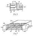
- FIG. 3 One example of a suitable microwave attenuating device is shown in Figure 3, wherein the device 13 consists of a conventional quarter-wave choke.
- the choke consists of a metallic, shortcircuited stub 22, having a rectangular cross- section, which fits over ceramic end cap 23 of the lamp and surrounds lamp lead 24.
- the stub 22 has a length commensurate with a quarter of the wavelength of the microwave energy, which produces an electrical open-circuit to propagating microwaves, thereby inhibiting their transmission along the lamp lead 24.
- the stub 22 encloses the end caps of both of the lamps in each unit, but each lamp may alternatively be provided with an individual stub.
- the temperature of the pinch seals of the lamps should not exceed approximately 350°C to prevent damage to the lamps due to overheating and, to this end, a number of holes (not shown) are preferably provided in some or all of the top and side walls and the base of the attenuating device 13 to increase air circulation and reduce thermal conduction from the oven cavity.
- the microwave attenuating device 13 inhibits microwave leakage, it does not provide any protection for the lamps from the microwave energy and is thus insufficient by itself to inhibit damage to the lamps and a reduction in their operative life.
- Major causes of lamp failure due to exposure to microwave energy are arcing through the lamp, which occurs when the gaseous fill is ionised by the microwave energy, and the formation of localised hotspots within the lamp.
- the lamps are provided with one or more modifications to alleviate the above problems of arcing and/or localised hotspots.
- a first modification is to the support coils 16, which, in conventional tungsten-halogen lamps, each consists of more than one complete turn, generally 4/3 turns, of the wire portion curled around the inner wall of the envelope.
- the coil length is reduced to less than one complete turn, preferably to 3/4 or 7/8 of a turn, as shown in Figure 2, thereby inhibiting arcing which tends to occur between adjacent turns of a conventional support coil, when the lamp is exposed to microwave energy.
- the coil diameter is 7.7-7.8mm and the gap left in the coil turn around the inner wall of the envelope is 2-3mm.
- a second modification is to the gaseous fill of the lamps, which conventionally consists predominantly of an inert gas, usually argon, together with a halogen additive sufficient in quantity to provide the regenerative cycle.
- a halogen additive sufficient in quantity to provide the regenerative cycle.
- a third modification of the lamps is to the positioning of the electrical connection between the tail wire 18 and the end of the filament 14.
- this connection When this connection is exposed to relatively high intensities of microwave energy, it tends to form a localised hotspot, which may cause a visual disturbance to a user of the microwave oven, as well as reducing the life of the lamp.
- the lamp is arranged such that the electrical connection is shielded from the microwave energy by positioning it adjacent a wall of the metallic casing 8, as shown by the connection between tail wire 18 and filament 14 adjacent wall 25 of the casing 8.
- the metallic wall 8 thus acts as a shield to protect the electrical connection from the microwave energy.
- a lamp unit as shown in Figures 4 to 6 consists of an upper casing 30 and a lower casing 31, both preferably made of metal, such as stainless steel.
- Two infra-red lamps 32, 33 are accommodated in the unit, each lamp, comprising a tungsten linear or coiled coil filament 34 supported by support coils 35, modified as described above, in a halogenated quartz envelope 36.
- Each end of each lamp is sealed by a pinch seal (not shown) enclosed in a ceramic end cap 37, from which an electrical lead 38 is emergent for connection of the filament to an external power supply (not shown).
- Adjacent the lamps 32, 33 is a layer 10 of thermally-insulative material, which is preferably a ceramic fibre and may be reflective of infra-red radiation emitted by the lamps.
- the lamps 32, 33 are retained in the unit adjacent their ends by a rectangular portion 40 of thermal insulation, which may also consist of ceramic fibre. Also retaining the lamps are two dividing walls 41, 42, which partition the filament portion of the lamps from its end portions.
- the lower casing 31 is open, at least in the vicinity of the lamp filaments, so that infra-red radiation generated by the lamps can be emitted out of the unit.
- the unit When used in a microwave oven, the unit is positioned so as to open into the oven cavity, so that food cooked by the microwave energy in the oven can be browned by infra-red radiation from the lamps.
- the leads 38 for the lamps are separately emergent from the unit and each lead is provided with an individual quarter-wave choke 43, which inhibits transmission of microwave energy along the lead.
- external leads 44 may be connected together to a common power supply (not shown).
- the length of lead 38 within the unit is minimised, which inhibits the generation of high-frequency currents in the leads.
- the unit consisting of upper and lower casings 30, 31, has also been designed to have increased rigidity and strength, and the individual chokes 43 have been fixed to the unit casing by screw-thread (not shown), which both aid in reducing the leakage of microwave energy from the unit.
- Figure 7 shows an alternative arrangement of the microwave attenuating device shown in Figures 1 to 5.
- Figure 7 shows schematically an end perspective view of a lamp unit, showing two end caps 45, 46 of the lamps of the unit.
- lamp leads 47, 48 extend laterally from the end caps 45, 46 respectively and respectively pass through two microwave attenuating devices 49, 50.
- a metal mesh 51 Between the two devices 49, 50 and surrounding the end caps 45, 46 is a metal mesh 51, which is attached to the metallic casing 52 of the unit.
- the mesh 51 permits sufficient cooling of the lamp ends, as well as inhibiting leakage of the microwave energy propogated along the lamp leads.
- microwave attenuating devices shown in the Figures may consist of any suitable arrangement, such as the quarter wave choke shown in Figures 2 and 3.
- An alternative suitable device may include microwave absorbent materials, such as ferrite, which absorbs microwaves as they propagate down the lamp leads.
- microwave absorbent materials such as ferrite
- a conventional embodiment of such a device includes one or more ferrite beads threaded onto the lamp lead and then enclosed within a metallic sleeve.
Description
- This invention relates to a microwave oven and in particular to such an oven including tungsten-halogen lamps as a means for browning food cooked by the microwave energy.
- A microwave oven of this type is described in our copending UK Patent Pubn. No. 2152790A, wherein, in one embodiment, two heating units, each containing two tungsten-halogen lamps, are located at predetermined positions adjacent openings into the oven cavity, so that infra-red radiation generated by the lamps is emitted towards food within the oven cavity to effect optimum browning thereof. Each lamp comprises a tungsten filament supported by spiral supports within a sealed, halogenated quartz envelope.
- To prevent damage to the lamps, it is necessary to protect them from the microwave energy within the cavity, and to this end the above-mentioned Patent Pubn. No. 2152790A describes in one embodiment the provision of a protective screen, positioned over the opening and having a number of apertures dimensioned to inhibit the passage of microwave energy through it, whilst permitting the passage of infra-red radiation. As alternative or additional protection for the lamps, a microwave choke arrangement may be used, which consists of waveguides dimensioned and located relative to the lamps to inhibit transmission of microwave energy from within the oven cavity to the lamps.
- However, the use of a choke arrangement alone may not be sufficient protection for the lamps, which still tend to be exposed to sufficient microwave energy to cause ionisation of the gaseous fill of the lamps. This can lead to arcing through the lamps and/or the formation of localised hotspots, which may cause a break down in the regenerative halogen cycle, or overheating which can cause the lamp filaments to flare, thereby substantially reducing the operative life of the lamps.
- It is therefore an object of the present invention to provide a microwave oven including an improved tungsten-halogen lamp, which is less vulnerable to damage, when exposed to microwave energy, by inhibiting arcing and/or the formation of localised hotspots within the lamp or overheating of the lamp, which can result from exposure of conventional lamps to microwave energy.
- In accordance with the present invention, there is provided a microwave oven comprising a source of microwave energy and at least one source of infra-red radiation, said at least one infra-red source including an infra-red-emissive lamp comprising a tungsten filament supported by a number of spaced support coils within a gas filled tubular envelope, said gaseous fill comprising a halogen, each of said coils consisting of a wire having first and second portions, said first portion being attached at one of its ends to said filament and extending at its other end into said second portion which is curled around the inner wall of said envelope, characterised in that said second portion of said wire extends less than a complete turn around the inner wall of said envelope.
- The gaseous fill of the tungsten-halogen lamp preferably consists predominantly of nitrogen with a halogen additive to inhibit arcing between the ends and/or the filament of the lamps, which can occur if other gases, such as argon, are used instead of nitrogen.
- Each end of the lamp filament within the envelope is provided with an electrical connection to connect the filament to a power supply located externally of the lamp, and each electrical connection of the lamp filament is preferably positioned so as to be shielded from the microwave energy by a wall of a metallic casing accommodating the lamp, thereby inhibiting the formation of localised hotspots at the electrical connection.
- When more than one lamp is accommodated in a unit, preferably the location of any electrical interconnection between the lamps is external of the unit to inhibit the generation of high-frequency currents circulating through the lamps.
- It is also preferable that the length of electrical lead of each lamp located inside the unit is minimised, to inhibit the generation of high-frequency currents in the leads.
- The invention will now be further described by way of example only with reference to the accompanying drawings, wherein:-
- Figure 1 shows a schematic sectional view of a microwave oven incorporating tungsten-halogen lamp units,
- Figure 2 shows a more detailed schematic plan view of a lamp unit shown in Figure 1, incorporating the present invention,
- Figure 3 shows a sectional view through I-I in Figure 2,
- Figure 4 shows schematically an underside plan view of a second embodiment of a lamp unit, in accordance with the invention,
- Figure 5 shows schematically a sectional view through II-II in Figure 4,
- Figure 6 shows schematically a sectional view through III-III in Figure 5, and
- Figure 7 shows a schematic perspective end view of part of a third embodiment of a lamp unit.
- A microwave oven, shown in Figure 1, consists of an
oven cavity 1 containing a turntable 2, upon which food is supported to be cooked by microwave energy emitted from a source (not shown) and directed into theoven cavity 1 by aconventional waveguide 3, stirrer and/or other suitable means. - Two
lamp units 4, 5 are positioned outside of thecavity 1 at predetermined locations adjacent respective openings inside wall 6 andtop wall 7 of thecavity 1. Eachlamp unit 4, 5 consists of ametallic casing 8 accommodating tungsten-halogen lamps, such as at 9, around which a thermally-insulative orceramic material 10 is provided to alleviate dissipation of heat from theunit 4,5 and partially to reflect infra-red radiation emitted from the lamps, as well as providing support for the lamps. - The lamps 9 generate radiation in the near- infra-red range within a wavelength band of 0.8-5 µm with a peak at approximately 1.2 pm.
- A protective screen 11 is positioned over each opening into the
cavity 1, the screen being formed from any suitable infra-red-transmissive material, such as glass ceramic, to prevent the lamps and the interior of the unit from being damaged and/ or soiled by food particles or other cooking products dissipated from food being cooked in thecavity 1. - Infra-red radiation emitted from the lamps 9 is thus directed into the
oven cavity 1, through the screen 11, to brown food being cooked by the microwave energy, thelamp units 4, 5 being positioned at predetermined locations to achieve an optimum browning effect. - The protective screen 11 does not prevent exposure of the lamps to the microwave energy, so that microwave energy can be transmitted from the lamp filament to lamp leads 12 and thus to outside of the
cavity 1, causing an unacceptable leakage of the microwave energy. To inhibit such leaks, the ends of each lamp 9 is provided with a microwave attenuating device, attached to thecasing 8, as shown in outline at 13, which will be described in more detail hereinafter. - One of the lamp units 4 is shown in more detail in the plan view of Figure 2, wherein like parts are labelled with like reference numerals, with respect to Figure 1.
- Each lamp 9 of the unit 4 consists of a linear or coiled
coil tungsten filament 14 supported within atubular quartz envelope 15 by a number of spaced support coils, such as at 16, each consisting of a coiled wire having a first portion wrapped, at one end, around thefilament 14 and extending radially in the envelope to form a second portion curled around the inner wall of theenvelope 15. - Each end of the
filament 14 is electrically connected to theflying lead 12, or other suitable connector, for connection to a power supply for the lamp, via amolybdenum foil 17 and atail wire 18 sealed within apinch seal 19 of theenvelope 15.End 20 of thetail wire 18 emergent from thepinch seal 19 is formed into a short coil, which is interlinked with the end turns of thefilament 14 to provide the electrical connection. - The
envelope 15 has a gaseous fill sealed therein, which fill includes a halogen additive, providing a regenerative halogen cycle to increase the longevity of the lamp filament. - The pinch seal at the ends of each lamp are preferably enclosed within a ceramic housing, such as at 21, the housing for
pinch seal 19 having been removed to reveal the pinch seal construction. Theceramic housings 21 are provided to protect the pinch seals from mechanical damage and/or overheating by exposure to infra-red radiation from the filament. - As indicated in Figure 1, the ends of the lamps are enclosed within a microwave attenuating
device 13, the device at one end of the unit shown in Figure 2 having been removed for clarity. - One example of a suitable microwave attenuating device is shown in Figure 3, wherein the
device 13 consists of a conventional quarter-wave choke. The choke consists of a metallic,shortcircuited stub 22, having a rectangular cross- section, which fits overceramic end cap 23 of the lamp and surroundslamp lead 24. Thestub 22 has a length commensurate with a quarter of the wavelength of the microwave energy, which produces an electrical open-circuit to propagating microwaves, thereby inhibiting their transmission along thelamp lead 24. Preferably, thestub 22 encloses the end caps of both of the lamps in each unit, but each lamp may alternatively be provided with an individual stub. - The temperature of the pinch seals of the lamps should not exceed approximately 350°C to prevent damage to the lamps due to overheating and, to this end, a number of holes (not shown) are preferably provided in some or all of the top and side walls and the base of the
attenuating device 13 to increase air circulation and reduce thermal conduction from the oven cavity. - Although the microwave attenuating
device 13 inhibits microwave leakage, it does not provide any protection for the lamps from the microwave energy and is thus insufficient by itself to inhibit damage to the lamps and a reduction in their operative life. Major causes of lamp failure due to exposure to microwave energy are arcing through the lamp, which occurs when the gaseous fill is ionised by the microwave energy, and the formation of localised hotspots within the lamp. - To substantially reduce the vulnerability of the lamps to the microwave energy, in accordance with the present invention, the lamps are provided with one or more modifications to alleviate the above problems of arcing and/or localised hotspots.
- A first modification is to the
support coils 16, which, in conventional tungsten-halogen lamps, each consists of more than one complete turn, generally 4/3 turns, of the wire portion curled around the inner wall of the envelope. However, it has been found to be advantageous to reduce the coil length to less than one complete turn, preferably to 3/4 or 7/8 of a turn, as shown in Figure 2, thereby inhibiting arcing which tends to occur between adjacent turns of a conventional support coil, when the lamp is exposed to microwave energy. In a preferred construction, the coil diameter is 7.7-7.8mm and the gap left in the coil turn around the inner wall of the envelope is 2-3mm. - A second modification is to the gaseous fill of the lamps, which conventionally consists predominantly of an inert gas, usually argon, together with a halogen additive sufficient in quantity to provide the regenerative cycle. However, it has been found to be particularly advantageous to utilise a fill predominantly of nitrogen with a halogen additive, which is less susceptible to ionisation by the microwave energy, and thus to arcing between the lamp ends and/or the filament, than conventionally used fills.
- A third modification of the lamps is to the positioning of the electrical connection between the
tail wire 18 and the end of thefilament 14. When this connection is exposed to relatively high intensities of microwave energy, it tends to form a localised hotspot, which may cause a visual disturbance to a user of the microwave oven, as well as reducing the life of the lamp. To inhibit the formation of such a hotspot, the lamp is arranged such that the electrical connection is shielded from the microwave energy by positioning it adjacent a wall of themetallic casing 8, as shown by the connection betweentail wire 18 andfilament 14adjacent wall 25 of thecasing 8. Themetallic wall 8 thus acts as a shield to protect the electrical connection from the microwave energy. - It can thus be envisaged that by using one or more, and preferably all three, of the above-described modifications, the vulnerability of the lamps to damage by microwave energy is substantially reduced, thus increasing the operative life of the lamps.
- In another embodiment a lamp unit as shown in Figures 4 to 6, consists of an
upper casing 30 and alower casing 31, both preferably made of metal, such as stainless steel. Two infra-red lamps coiled coil filament 34 supported bysupport coils 35, modified as described above, in ahalogenated quartz envelope 36. Each end of each lamp is sealed by a pinch seal (not shown) enclosed in aceramic end cap 37, from which anelectrical lead 38 is emergent for connection of the filament to an external power supply (not shown). - Adjacent the
lamps layer 10 of thermally-insulative material, which is preferably a ceramic fibre and may be reflective of infra-red radiation emitted by the lamps. Thelamps rectangular portion 40 of thermal insulation, which may also consist of ceramic fibre. Also retaining the lamps are two dividingwalls - The
lower casing 31 is open, at least in the vicinity of the lamp filaments, so that infra-red radiation generated by the lamps can be emitted out of the unit. - When used in a microwave oven, the unit is positioned so as to open into the oven cavity, so that food cooked by the microwave energy in the oven can be browned by infra-red radiation from the lamps.
- To inhibit overheating, and thus flaring, of the lamps, which is caused by exposure of the lamps to microwave energy, in addition to one or more of the above-described modifications to the lamp, it has been found advantageous to ensure that any electrical interconnection between the lamps of the unit is made externally of the unit and/or that the length of the lamp lead within the unit is minimised.
- To this end, the
leads 38 for the lamps are separately emergent from the unit and each lead is provided with an individual quarter-wave choke 43, which inhibits transmission of microwave energy along the lead. Once outside of the unit, external leads 44 may be connected together to a common power supply (not shown). - As the lamps are separate from each other within the unit, the generation of circulating high-frequency currents through the lamps, which cause overheating and thus flaring of the lamps, is inhibited.
- Additionally or alternatively, the length of
lead 38 within the unit is minimised, which inhibits the generation of high-frequency currents in the leads. - Furthermore, the unit, consisting of upper and
lower casings - Figure 7 shows an alternative arrangement of the microwave attenuating device shown in Figures 1 to 5. Figure 7 shows schematically an end perspective view of a lamp unit, showing two
end caps microwave attenuating devices 49, 50. Between the twodevices 49, 50 and surrounding the end caps 45, 46 is ametal mesh 51, which is attached to themetallic casing 52 of the unit. Themesh 51 permits sufficient cooling of the lamp ends, as well as inhibiting leakage of the microwave energy propogated along the lamp leads. - The microwave attenuating devices shown in the Figures may consist of any suitable arrangement, such as the quarter wave choke shown in Figures 2 and 3.
- An alternative suitable device may include microwave absorbent materials, such as ferrite, which absorbs microwaves as they propagate down the lamp leads. A conventional embodiment of such a device includes one or more ferrite beads threaded onto the lamp lead and then enclosed within a metallic sleeve.
Claims (7)
Priority Applications (1)
| Application Number | Priority Date | Filing Date | Title |
|---|---|---|---|
| AT86309005T ATE59929T1 (en) | 1985-11-30 | 1986-11-18 | MICROWAVE OVEN. |
Applications Claiming Priority (4)
| Application Number | Priority Date | Filing Date | Title |
|---|---|---|---|
| GB858529580A GB8529580D0 (en) | 1985-11-30 | 1985-11-30 | Microwave ovens |
| GB8617056 | 1985-11-30 | ||
| GB868617056A GB8617056D0 (en) | 1986-07-12 | 1986-07-12 | Microwave ovens |
| GB8529580 | 1986-07-12 |
Publications (3)
| Publication Number | Publication Date |
|---|---|
| EP0226343A2 EP0226343A2 (en) | 1987-06-24 |
| EP0226343A3 EP0226343A3 (en) | 1988-03-30 |
| EP0226343B1 true EP0226343B1 (en) | 1991-01-09 |
Family
ID=26290060
Family Applications (1)
| Application Number | Title | Priority Date | Filing Date |
|---|---|---|---|
| EP86309005A Expired - Lifetime EP0226343B1 (en) | 1985-11-30 | 1986-11-18 | Microwave oven |
Country Status (9)
| Country | Link |
|---|---|
| US (1) | US4728763A (en) |
| EP (1) | EP0226343B1 (en) |
| DE (1) | DE3676797D1 (en) |
| DK (1) | DK165152C (en) |
| ES (1) | ES2019292B3 (en) |
| FI (1) | FI83377C (en) |
| GR (1) | GR3001377T3 (en) |
| NO (1) | NO164199C (en) |
| NZ (1) | NZ218421A (en) |
Families Citing this family (18)
| Publication number | Priority date | Publication date | Assignee | Title |
|---|---|---|---|---|
| US5082999A (en) * | 1989-06-13 | 1992-01-21 | Matsushita Electric Industrial Co., Ltd. | Microwave oven having device for preventing concentration of microwaves on heater element |
| DE3931859A1 (en) * | 1989-09-23 | 1991-04-04 | Bauknecht Hausgeraete | ELECTRIC COOKER |
| KR930015967A (en) * | 1991-12-03 | 1993-07-24 | 강진구 | Microwave Heater |
| SE513851C2 (en) * | 1997-01-30 | 2000-11-13 | Whirlpool Europ | Heating element |
| US5990454A (en) | 1997-09-23 | 1999-11-23 | Quadlux, Inc. | Lightwave oven and method of cooking therewith having multiple cook modes and sequential lamp operation |
| US6013900A (en) | 1997-09-23 | 2000-01-11 | Quadlux, Inc. | High efficiency lightwave oven |
| US5958271A (en) | 1997-09-23 | 1999-09-28 | Quadlux, Inc. | Lightwave oven and method of cooking therewith with cookware reflectivity compensation |
| KR100301904B1 (en) * | 1997-11-15 | 2001-11-22 | 구자홍 | Apparatus for cooling microwave oven with halogen lamp |
| KR100307354B1 (en) * | 1998-07-29 | 2002-07-03 | 구자홍 | Microwave oven with halogen lamp |
| KR100533271B1 (en) * | 1998-07-29 | 2006-09-20 | 주식회사 엘지이아이 | Microwave Oven with Microwave Shutoff |
| US6263830B1 (en) | 1999-04-12 | 2001-07-24 | Matrix Integrated Systems, Inc. | Microwave choke for remote plasma generator |
| US6521870B2 (en) | 2001-01-11 | 2003-02-18 | General Electric Company | Thermal/convection oven including halogen lamps |
| US20050258171A1 (en) * | 2004-05-10 | 2005-11-24 | Hatco Corporation | Microwave oven with infrared heat |
| EP1792120B1 (en) * | 2004-09-16 | 2014-07-30 | Speziallampenfabrik Dr. Fischer GmbH | Lamp assembly with lamp and reflector |
| GB2515075B (en) | 2013-06-13 | 2018-07-11 | Kenwood Ltd | Improved electric toaster |
| KR102084043B1 (en) * | 2013-09-27 | 2020-03-04 | 엘지전자 주식회사 | Cooking appliance |
| CN109644526A (en) * | 2016-09-15 | 2019-04-16 | 惠而浦有限公司 | Micro-wave oven apparatus for baking with efficient honeycomb-like pattern grid member |
| EP3707962A4 (en) * | 2017-11-06 | 2021-12-08 | Brava Home, Inc. | Spectral power density configuration in a cooking instrument |
Family Cites Families (6)
| Publication number | Priority date | Publication date | Assignee | Title |
|---|---|---|---|---|
| JPS5813929A (en) * | 1981-07-20 | 1983-01-26 | Matsushita Electric Ind Co Ltd | High frequency heating device with electric heater |
| US4493960A (en) * | 1982-08-12 | 1985-01-15 | Micro-Quartz Technology Corp. | Ceramic blinders for a microwave oven quartz lamp |
| US4485285A (en) * | 1983-03-07 | 1984-11-27 | Control Data Corporation | Quarterwave choke for a microwave oven quartz lamp |
| GB8308103D0 (en) * | 1983-03-24 | 1983-05-05 | Emi Plc Thorn | Quartz infra-red lamps |
| GB2152790B (en) * | 1983-12-02 | 1986-11-05 | Thorn Emi Domestic Appliances | Additional heating in microwave ovens |
| EP0162620A3 (en) * | 1984-05-11 | 1987-05-13 | THORN EMI Patents Limited | A cooking arrangement |
-
1986
- 1986-11-18 DE DE8686309005T patent/DE3676797D1/en not_active Expired - Lifetime
- 1986-11-18 ES ES86309005T patent/ES2019292B3/en not_active Expired - Lifetime
- 1986-11-18 EP EP86309005A patent/EP0226343B1/en not_active Expired - Lifetime
- 1986-11-26 FI FI864823A patent/FI83377C/en not_active IP Right Cessation
- 1986-11-27 NO NO864784A patent/NO164199C/en unknown
- 1986-11-27 DK DK571686A patent/DK165152C/en not_active IP Right Cessation
- 1986-11-27 NZ NZ218421A patent/NZ218421A/en unknown
- 1986-11-28 US US06/935,928 patent/US4728763A/en not_active Expired - Fee Related
-
1991
- 1991-01-24 GR GR91400081T patent/GR3001377T3/en unknown
Also Published As
| Publication number | Publication date |
|---|---|
| GR3001377T3 (en) | 1992-09-11 |
| EP0226343A3 (en) | 1988-03-30 |
| DK571686A (en) | 1987-05-31 |
| FI83377C (en) | 1991-06-25 |
| NO864784D0 (en) | 1986-11-27 |
| DE3676797D1 (en) | 1991-02-14 |
| NO164199C (en) | 1990-09-05 |
| DK571686D0 (en) | 1986-11-27 |
| FI864823A0 (en) | 1986-11-26 |
| US4728763A (en) | 1988-03-01 |
| FI864823A (en) | 1987-05-31 |
| ES2019292B3 (en) | 1991-06-16 |
| DK165152B (en) | 1992-10-12 |
| NO164199B (en) | 1990-05-28 |
| EP0226343A2 (en) | 1987-06-24 |
| DK165152C (en) | 1993-02-22 |
| FI83377B (en) | 1991-03-15 |
| NZ218421A (en) | 1989-11-28 |
Similar Documents
| Publication | Publication Date | Title |
|---|---|---|
| EP0226343B1 (en) | Microwave oven | |
| EP0226407A2 (en) | An oven | |
| US4598194A (en) | Quartz infra-red lamps | |
| EP0976975B1 (en) | Cooling device for halogen lamps in microwave ovens | |
| JPH0782832B2 (en) | Electrodeless fluorescent lamp | |
| EP0447852B1 (en) | Luminaire for an electrodeless high intensity discharge lamp with electromagnetic interference shielding | |
| US3995193A (en) | Microwave tube having structure for preventing the leakage of microwave radiation | |
| GB2048560A (en) | Electrodeless gas discharge lamp | |
| CA1256509A (en) | Microwave oven | |
| JP3277215B2 (en) | Unwanted electron wave shielding structure of magnetron for microwave oven | |
| EP0565375A1 (en) | Double-ended arc discharge lamps | |
| CN214753633U (en) | Magnetron filtering component, magnetron and household appliance | |
| CA1114453A (en) | Combination microwave and resistively heated oven | |
| KR19990007961A (en) | Compact microwave lamp | |
| EP0409323B1 (en) | Microwave oven | |
| JPS6123638B2 (en) | ||
| AU2004306548A1 (en) | A radiant device | |
| CN215187470U (en) | Microwave suppression structure and oven | |
| JP3924884B2 (en) | High frequency heating device | |
| JPH09306434A (en) | Tungsten halogen lamp | |
| JPH0136680B2 (en) | ||
| KR100861948B1 (en) | Electromagnetic wave shielded apparatus of a heating cooker | |
| KR930005051Y1 (en) | Magnetron | |
| JPH0395892A (en) | High frequency heating device | |
| KR19980050371U (en) | Heater installation structure of microwave oven |
Legal Events
| Date | Code | Title | Description |
|---|---|---|---|
| PUAI | Public reference made under article 153(3) epc to a published international application that has entered the european phase |
Free format text: ORIGINAL CODE: 0009012 |
|
| AK | Designated contracting states |
Kind code of ref document: A2 Designated state(s): AT BE CH DE ES FR GB GR IT LI LU NL SE |
|
| RAP1 | Party data changed (applicant data changed or rights of an application transferred) |
Owner name: THORN EMI PATENTS LIMITED |
|
| PUAL | Search report despatched |
Free format text: ORIGINAL CODE: 0009013 |
|
| AK | Designated contracting states |
Kind code of ref document: A3 Designated state(s): AT BE CH DE ES FR GB GR IT LI LU NL SE |
|
| 17P | Request for examination filed |
Effective date: 19880711 |
|
| 17Q | First examination report despatched |
Effective date: 19891128 |
|
| GRAA | (expected) grant |
Free format text: ORIGINAL CODE: 0009210 |
|
| AK | Designated contracting states |
Kind code of ref document: B1 Designated state(s): AT BE CH DE ES FR GB GR IT LI LU NL SE |
|
| REF | Corresponds to: |
Ref document number: 59929 Country of ref document: AT Date of ref document: 19910115 Kind code of ref document: T |
|
| REF | Corresponds to: |
Ref document number: 3676797 Country of ref document: DE Date of ref document: 19910214 |
|
| ET | Fr: translation filed | ||
| ITF | It: translation for a ep patent filed |
Owner name: FUMERO BREVETTI S.N.C. |
|
| PLBE | No opposition filed within time limit |
Free format text: ORIGINAL CODE: 0009261 |
|
| STAA | Information on the status of an ep patent application or granted ep patent |
Free format text: STATUS: NO OPPOSITION FILED WITHIN TIME LIMIT |
|
| 26N | No opposition filed | ||
| REG | Reference to a national code |
Ref country code: GR Ref legal event code: FG4A Free format text: 3001377 |
|
| PGFP | Annual fee paid to national office [announced via postgrant information from national office to epo] |
Ref country code: GB Payment date: 19921005 Year of fee payment: 7 |
|
| PGFP | Annual fee paid to national office [announced via postgrant information from national office to epo] |
Ref country code: CH Payment date: 19921012 Year of fee payment: 7 |
|
| PGFP | Annual fee paid to national office [announced via postgrant information from national office to epo] |
Ref country code: SE Payment date: 19921013 Year of fee payment: 7 |
|
| PGFP | Annual fee paid to national office [announced via postgrant information from national office to epo] |
Ref country code: LU Payment date: 19921014 Year of fee payment: 7 Ref country code: AT Payment date: 19921014 Year of fee payment: 7 |
|
| PGFP | Annual fee paid to national office [announced via postgrant information from national office to epo] |
Ref country code: FR Payment date: 19921026 Year of fee payment: 7 |
|
| PGFP | Annual fee paid to national office [announced via postgrant information from national office to epo] |
Ref country code: ES Payment date: 19921028 Year of fee payment: 7 |
|
| PGFP | Annual fee paid to national office [announced via postgrant information from national office to epo] |
Ref country code: GR Payment date: 19921029 Year of fee payment: 7 |
|
| PGFP | Annual fee paid to national office [announced via postgrant information from national office to epo] |
Ref country code: BE Payment date: 19921104 Year of fee payment: 7 |
|
| PGFP | Annual fee paid to national office [announced via postgrant information from national office to epo] |
Ref country code: NL Payment date: 19921130 Year of fee payment: 7 |
|
| PGFP | Annual fee paid to national office [announced via postgrant information from national office to epo] |
Ref country code: DE Payment date: 19930127 Year of fee payment: 7 |
|
| EPTA | Lu: last paid annual fee | ||
| PG25 | Lapsed in a contracting state [announced via postgrant information from national office to epo] |
Ref country code: LU Free format text: LAPSE BECAUSE OF NON-PAYMENT OF DUE FEES Effective date: 19931118 Ref country code: GB Effective date: 19931118 Ref country code: AT Effective date: 19931118 |
|
| PG25 | Lapsed in a contracting state [announced via postgrant information from national office to epo] |
Ref country code: SE Effective date: 19931119 Ref country code: ES Free format text: LAPSE BECAUSE OF EXPIRATION OF PROTECTION Effective date: 19931119 |
|
| PG25 | Lapsed in a contracting state [announced via postgrant information from national office to epo] |
Ref country code: LI Effective date: 19931130 Ref country code: CH Effective date: 19931130 Ref country code: BE Effective date: 19931130 |
|
| BERE | Be: lapsed |
Owner name: THORN EMI PATENTS LTD Effective date: 19931130 |
|
| PG25 | Lapsed in a contracting state [announced via postgrant information from national office to epo] |
Ref country code: GR Free format text: THE PATENT HAS BEEN ANNULLED BY A DECISION OF A NATIONAL AUTHORITY Effective date: 19940531 |
|
| PG25 | Lapsed in a contracting state [announced via postgrant information from national office to epo] |
Ref country code: NL Effective date: 19940601 |
|
| GBPC | Gb: european patent ceased through non-payment of renewal fee |
Effective date: 19931118 |
|
| NLV4 | Nl: lapsed or anulled due to non-payment of the annual fee | ||
| PG25 | Lapsed in a contracting state [announced via postgrant information from national office to epo] |
Ref country code: FR Effective date: 19940729 |
|
| REG | Reference to a national code |
Ref country code: CH Ref legal event code: PL |
|
| PG25 | Lapsed in a contracting state [announced via postgrant information from national office to epo] |
Ref country code: DE Effective date: 19940802 |
|
| REG | Reference to a national code |
Ref country code: FR Ref legal event code: ST |
|
| REG | Reference to a national code |
Ref country code: GR Ref legal event code: MM2A Free format text: 3001377 |
|
| EUG | Se: european patent has lapsed |
Ref document number: 86309005.6 Effective date: 19940610 |
|
| REG | Reference to a national code |
Ref country code: ES Ref legal event code: FD2A Effective date: 20010301 |
|
| PG25 | Lapsed in a contracting state [announced via postgrant information from national office to epo] |
Ref country code: IT Free format text: LAPSE BECAUSE OF NON-PAYMENT OF DUE FEES;WARNING: LAPSES OF ITALIAN PATENTS WITH EFFECTIVE DATE BEFORE 2007 MAY HAVE OCCURRED AT ANY TIME BEFORE 2007. THE CORRECT EFFECTIVE DATE MAY BE DIFFERENT FROM THE ONE RECORDED. Effective date: 20051118 |