EP0225752A2 - Ball valve - Google Patents
Ball valve Download PDFInfo
- Publication number
- EP0225752A2 EP0225752A2 EP86309023A EP86309023A EP0225752A2 EP 0225752 A2 EP0225752 A2 EP 0225752A2 EP 86309023 A EP86309023 A EP 86309023A EP 86309023 A EP86309023 A EP 86309023A EP 0225752 A2 EP0225752 A2 EP 0225752A2
- Authority
- EP
- European Patent Office
- Prior art keywords
- valve body
- seal carrier
- ball
- valve
- channel
- Prior art date
- Legal status (The legal status is an assumption and is not a legal conclusion. Google has not performed a legal analysis and makes no representation as to the accuracy of the status listed.)
- Granted
Links
- 239000012530 fluid Substances 0.000 claims description 11
- 238000007789 sealing Methods 0.000 claims description 11
- 230000008878 coupling Effects 0.000 claims description 6
- 238000010168 coupling process Methods 0.000 claims description 6
- 238000005859 coupling reaction Methods 0.000 claims description 6
- 238000010276 construction Methods 0.000 description 8
- 238000003780 insertion Methods 0.000 description 7
- 230000037431 insertion Effects 0.000 description 7
- 239000000463 material Substances 0.000 description 3
- 229920004943 Delrin® Polymers 0.000 description 2
- 230000004048 modification Effects 0.000 description 2
- 238000012986 modification Methods 0.000 description 2
- 239000004677 Nylon Substances 0.000 description 1
- 239000002033 PVDF binder Substances 0.000 description 1
- 239000004743 Polypropylene Substances 0.000 description 1
- 239000004809 Teflon Substances 0.000 description 1
- 229920006362 Teflon® Polymers 0.000 description 1
- 239000000969 carrier Substances 0.000 description 1
- 238000012423 maintenance Methods 0.000 description 1
- 229920001778 nylon Polymers 0.000 description 1
- 230000000737 periodic effect Effects 0.000 description 1
- 239000004033 plastic Substances 0.000 description 1
- 229920003023 plastic Polymers 0.000 description 1
- -1 polypropylene Polymers 0.000 description 1
- 229920001155 polypropylene Polymers 0.000 description 1
- 229920002981 polyvinylidene fluoride Polymers 0.000 description 1
- 229920005989 resin Polymers 0.000 description 1
- 239000011347 resin Substances 0.000 description 1
- 230000000717 retained effect Effects 0.000 description 1
- 239000003566 sealing material Substances 0.000 description 1
- 239000000126 substance Substances 0.000 description 1
Images

Classifications
-
- F—MECHANICAL ENGINEERING; LIGHTING; HEATING; WEAPONS; BLASTING
- F16—ENGINEERING ELEMENTS AND UNITS; GENERAL MEASURES FOR PRODUCING AND MAINTAINING EFFECTIVE FUNCTIONING OF MACHINES OR INSTALLATIONS; THERMAL INSULATION IN GENERAL
- F16K—VALVES; TAPS; COCKS; ACTUATING-FLOATS; DEVICES FOR VENTING OR AERATING
- F16K5/00—Plug valves; Taps or cocks comprising only cut-off apparatus having at least one of the sealing faces shaped as a more or less complete surface of a solid of revolution, the opening and closing movement being predominantly rotary
- F16K5/06—Plug valves; Taps or cocks comprising only cut-off apparatus having at least one of the sealing faces shaped as a more or less complete surface of a solid of revolution, the opening and closing movement being predominantly rotary with plugs having spherical surfaces; Packings therefor
- F16K5/0626—Easy mounting or dismounting means
-
- F—MECHANICAL ENGINEERING; LIGHTING; HEATING; WEAPONS; BLASTING
- F16—ENGINEERING ELEMENTS AND UNITS; GENERAL MEASURES FOR PRODUCING AND MAINTAINING EFFECTIVE FUNCTIONING OF MACHINES OR INSTALLATIONS; THERMAL INSULATION IN GENERAL
- F16K—VALVES; TAPS; COCKS; ACTUATING-FLOATS; DEVICES FOR VENTING OR AERATING
- F16K5/00—Plug valves; Taps or cocks comprising only cut-off apparatus having at least one of the sealing faces shaped as a more or less complete surface of a solid of revolution, the opening and closing movement being predominantly rotary
- F16K5/06—Plug valves; Taps or cocks comprising only cut-off apparatus having at least one of the sealing faces shaped as a more or less complete surface of a solid of revolution, the opening and closing movement being predominantly rotary with plugs having spherical surfaces; Packings therefor
- F16K5/0663—Packings
- F16K5/0673—Composite packings
-
- F—MECHANICAL ENGINEERING; LIGHTING; HEATING; WEAPONS; BLASTING
- F16—ENGINEERING ELEMENTS AND UNITS; GENERAL MEASURES FOR PRODUCING AND MAINTAINING EFFECTIVE FUNCTIONING OF MACHINES OR INSTALLATIONS; THERMAL INSULATION IN GENERAL
- F16K—VALVES; TAPS; COCKS; ACTUATING-FLOATS; DEVICES FOR VENTING OR AERATING
- F16K5/00—Plug valves; Taps or cocks comprising only cut-off apparatus having at least one of the sealing faces shaped as a more or less complete surface of a solid of revolution, the opening and closing movement being predominantly rotary
- F16K5/08—Details
- F16K5/14—Special arrangements for separating the sealing faces or for pressing them together
- F16K5/20—Special arrangements for separating the sealing faces or for pressing them together for plugs with spherical surfaces
- F16K5/201—Special arrangements for separating the sealing faces or for pressing them together for plugs with spherical surfaces with the housing or parts of the housing mechanically pressing the seal against the plug
Definitions
- THIS INVENTION relates to improvements in ball valves. More specifically, the invention relates to a ball valve structure in which at least one seal of the valve is releasably held in place by mounting the seal on a removable seal insert which is held in place in the valve body.
- Ball valves are very well known in the art as effective means for controlling the flow of fluid.
- Such valves generally comprise a rotatable spherical ball located in a chamber within the valve body.
- a fluid passageway through the ball permits the flow of fluid through the valve when the ball is in an open position.
- leakage of fluid through the valve is prevented.
- This requires the use of washers, gaskets, 0- rings and other sealing arrangements which contact the ball and the interior wall of the valve body to provide a tight, substantially leak-proof fit of the ball when the valve is closed.
- seals on opposite sides of the ball and adapted for sealingly contacting the ball in the open and closed positions thereof.
- One or both of the seals may be provided on a hollow cylindrical seal carrier which is removable from the valve body. It is necessary, in such constructions, to be able to assemble the valve with the ball already located inside the valve body and to be able to adjust the sealing pressure of the seals on the ball.
- the seal carrier is glued in place in the valve body, but such a construction is not readily adjustable.
- the seal carrier or a lock ring therefor is screwed into the valve body. The screwed-in constructions cannot be adjusted when the valve union is in place.
- the screwed-in constructions are not as safe as is desired. If the nut of the union is removed from the valve body while the ball valve is closed and is still under pressure, the pressure of the fluid presses the ball axially against the threads. This pressure can destroy the screw connection and cause the seal carrier and the ball to be blown out of the valve body, with possibly serious consequences.
- the removable seal carrier is held in place against the ball and the interior wall of the valve body by means of a bayonet-type mount.
- a bayonet-type mounting system typically involves one or more pins or other projections extending radially from the seal carrier which are received in one or more grooves on the interior wall of the valve body when the carrier is rotated.
- bayonet-type mount has various drawbacks which reduce its utility, namely: bayonet-type mounts can, at the most, provide a surface engagement area of only about 50% of the circumference of the valve body and bayonet-type mounts can cause mistakes in use because sometimes it is difficult to ascertain whether the pin-carrying seal carrier has been completely turned so as to be fully engaged and releasably locked in place.
- a ball valve for controlling the flow of fluid, comprising: a valve body, a ball located within said body, a removable seal carrier located within said valve body, said seal carrier having sealing means adapted to sealingly engage said ball and said valve body, holding means for releasably holding said seal carrier within said valve body, said holding means comprising a channel formed between said valve body and said removable seal carrier which channel communicates to the exterior of the valve by means of an aperture and a flexible, resilient strip disposed within said channel for releasably securing said removable seal carrier inside said valve body, said strip being removable from said channel via said aperture.
- a structure according to the invention can be made safer than comparable known valves because the connection between the seal carrier and the valve body can be made stronger. It is possible to remove the union nut while the valve is under pressure with reduced risk that the ball will be blown out of the valve body.
- the holding structure includes a flexible, durable locking strip which is inserted into an annular channel formed by and between the valve body and the cylindrical seal carrier, which channel extends circumferentially around the entire circumference of the seal carrier and the internal wall of the valve body.
- the locking strip solidly engages both the valve body and the seal carrier thereby holding the seal in position for sealing contact with the ball.
- the arrangement is such that the locking strip can be easily inserted or withdrawn from the annular channel via an opening or insertion slot leading to the annular channel.
- the locking strip insures that almost 100% of the circumference of the internal wall of the valve body is releasably fixedly interconnected with the seal carrier, thereby providing a more secure seal than can be obtained using a screwed-in or bayonet-type mount.
- the locking strip of the present invention will protrude from the opening or insertion slot if it is not in a fully installed position so that this condition will be readily observable.
- the locking strip can permit small adjustments of the position of seal carrier to be made from outside the valve so as to increase or decrease, as needed, the pressure of the seal against the ball.
- the seal carrier may be mounted so that it can slide axially in the valve body to a limited extent. The union nut and the internal coupling part of the union are used to hold the seal carrier in place and to adjust the sealing pressure.
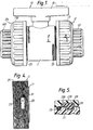
- the ball valve 10 comprises a generally cylindrical, hollow valve body 11 having threaded end portions 25 for threadably engaging screwed pipe unions 12 and 12A.
- the unions 12 and 12A are comprised of internally threaded, shouldered nuts 13 and 13A, the shoulders of which are engageable with the radially outwardly projecting flanges of the cylindrical, flanged coupling parts 14 and 14A.
- the handle 15 is connected by any suitable conventional means with the ball 16, to rotate the ball through an angle of 90° in order to open or close the valve.
- the ball 16 is located within the ball valve cavity 24 of the valve body and has a passageway 23 which permits fluid to flow therethrough.
- the ball 16 may be capable of a small amount of axial movement with respect to the valve body when the valve is in a closed position.
- a hollow, generally cylindrical, seal carrier 17 is disposed inside one end of the valve body 11 adjacent to the ball 16.
- the seal carrier 17 carries an annular seal ring 18 made of a durable, relatively low friction, sealing material, such as Teflon, nylon or Delrin, which seal ring sealingly and slidingly engages the outer surface of the ball 16 to prevent flow of fluid into the cavity 24 when the parts are in the open position as shown in Figure 2 and when the ball is rotated through an angle of 90 0 to the closed position.
- an O-ring 19 made of rubber or other suitable material is provided between the seal carrier 17 and the internal wall of the valve body 11 to minimise fluid leakage therebetween.
- a second O-ring 20 is provided between the flange of the coupling part 14 and the opposing axially outer end of the seal carrier 17.
- An annular groove 21 is formed in and extends circumferentially around the internal wall of the valve body 11.
- the seal carrier 17 has a recess 22 which is radially opposed to the groove 21 and has a radially outwardly projecting shoulder 26 at its axially inner end.
- a locking strip 27 is received in the groove 21 and the recess 22 to releasably lock the seal carrier 17 in place inside the valve body 11.
- the locking strip 27 is a radially split, annular ring of generally rectangular cross-section and It has a radially outwardly projecting locking pawl 28 at one free end of said strip.
- the seal carrier 17 is capable of being moved axially inwardly relative to locking strip 27 to adjust the sealing pressure between the seal 18 and ball 16 as described below.
- the seal carrier 17 can shift axially outwardly only until its shoulder 26 engages the opposing portion of the locking strip 27. Thus, the seal carrier 17 is safely retained in place within the valve body.
- the locking strip 27 is made of a flexible, durable material, such as Delrin resin, polypropylene, PVDF or other suitable plastics. The parts are assembled by inserting the seal carrier 17 into the valve body 11 until the groove 21 and recess 22 are aligned. Then the locking strip 27 is introduced into the insertion slot 29 and is fed into and pushed through the annular groove 21 until the parts are in the position shown in Figure 3 wherein the locking pawl 28 is received in the slot 29.
- a hole 31 is provided through the body of the pawl 28 of the locking strip 27 to facilitate mechanically engaging the locking strip 27 with a hook or other device to aid in removing the locking strip from the valve.
- the insertion slot 29 is located between and spaced from the axial ends of the threaded portion 25 of the valve body 11.
- the axially outer end of the seal carrier 17 projects a small distance outwardly beyond the axial end of the valve body 11.
- the flange of the coupling part 14 engages the axially outer end of the seal carrier 17 and the O-ring 20.
- the opposite end (leftward end in Figure 1) of the valve body also contains a seal carrier including a seal ring, like seal ring 18, for engaging the opposite side of the ball 16.
- This seal carrier can, if desired be of the same structure as seal carrier 17 and its associated parts. It is not usually necessary, however, to provide two removable seal carriers at opposite ends of the valve body 11. Rather, the seal carrier provided in the leftward end of the valve body can be integral with and not removable from the valve body, if desired.
- Figure 5 illustrates a modification in which the groove 21A has an axially inwardly extending portion 21B which extends substantially up to the O-ring.
- the locking strip 27A has an integral extension 27B which extends into and substantially fills the portion 21B. This modified design is useful to minimise the possibility that axially outward movement of the seal carrier 17 can roll the locking strip 27 out of the groove 21.
- the ball valves described with reference to the drawings are externally adjustable and are safer than the prior art constructions because the ball is prevented from being blown out of the valve body when the nut of the union is loosened.
Landscapes
- Engineering & Computer Science (AREA)
- General Engineering & Computer Science (AREA)
- Mechanical Engineering (AREA)
- Taps Or Cocks (AREA)
- External Artificial Organs (AREA)
- Temperature-Responsive Valves (AREA)
- Fuel-Injection Apparatus (AREA)
Abstract
Description
- THIS INVENTION relates to improvements in ball valves. More specifically, the invention relates to a ball valve structure in which at least one seal of the valve is releasably held in place by mounting the seal on a removable seal insert which is held in place in the valve body.
- Ball valves are very well known in the art as effective means for controlling the flow of fluid. Such valves generally comprise a rotatable spherical ball located in a chamber within the valve body. A fluid passageway through the ball permits the flow of fluid through the valve when the ball is in an open position. Ideally, when the ball is in the closed position leakage of fluid through the valve is prevented. This requires the use of washers, gaskets, 0- rings and other sealing arrangements which contact the ball and the interior wall of the valve body to provide a tight, substantially leak-proof fit of the ball when the valve is closed.
- These sealing systems are subject to wear because of contact with the movable ball, damage from exposure to extremes of temperature and pressure, or contact with harmful chemicals passing through the valve. Therefore, periodic maintenance of the sealing systems must be performed.
- It is known in the art to provide ball valve seals on opposite sides of the ball and adapted for sealingly contacting the ball in the open and closed positions thereof. One or both of the seals may be provided on a hollow cylindrical seal carrier which is removable from the valve body. It is necessary, in such constructions, to be able to assemble the valve with the ball already located inside the valve body and to be able to adjust the sealing pressure of the seals on the ball. In some constructions, the seal carrier is glued in place in the valve body, but such a construction is not readily adjustable. In other constructions, the seal carrier or a lock ring therefor, is screwed into the valve body. The screwed-in constructions cannot be adjusted when the valve union is in place. Also, the screwed-in constructions are not as safe as is desired. If the nut of the union is removed from the valve body while the ball valve is closed and is still under pressure, the pressure of the fluid presses the ball axially against the threads. This pressure can destroy the screw connection and cause the seal carrier and the ball to be blown out of the valve body, with possibly serious consequences. In another construction, the removable seal carrier is held in place against the ball and the interior wall of the valve body by means of a bayonet-type mount. A bayonet-type mounting system typically involves one or more pins or other projections extending radially from the seal carrier which are received in one or more grooves on the interior wall of the valve body when the carrier is rotated. Such a bayonet-type mount has various drawbacks which reduce its utility, namely: bayonet-type mounts can, at the most, provide a surface engagement area of only about 50% of the circumference of the valve body and bayonet-type mounts can cause mistakes in use because sometimes it is difficult to ascertain whether the pin-carrying seal carrier has been completely turned so as to be fully engaged and releasably locked in place.
- It is an object of the invention to provide a ball valve having improved means for holding a seal in place against the ball of a ball valve.
- According to the invention there is provided a ball valve for controlling the flow of fluid, comprising: a valve body, a ball located within said body, a removable seal carrier located within said valve body, said seal carrier having sealing means adapted to sealingly engage said ball and said valve body, holding means for releasably holding said seal carrier within said valve body, said holding means comprising a channel formed between said valve body and said removable seal carrier which channel communicates to the exterior of the valve by means of an aperture and a flexible, resilient strip disposed within said channel for releasably securing said removable seal carrier inside said valve body, said strip being removable from said channel via said aperture.
- A structure according to the invention can be made safer than comparable known valves because the connection between the seal carrier and the valve body can be made stronger. It is possible to remove the union nut while the valve is under pressure with reduced risk that the ball will be blown out of the valve body. The holding structure includes a flexible, durable locking strip which is inserted into an annular channel formed by and between the valve body and the cylindrical seal carrier, which channel extends circumferentially around the entire circumference of the seal carrier and the internal wall of the valve body. The locking strip solidly engages both the valve body and the seal carrier thereby holding the seal in position for sealing contact with the ball. The arrangement is such that the locking strip can be easily inserted or withdrawn from the annular channel via an opening or insertion slot leading to the annular channel.
- Several advantages are achieved by the invention. The locking strip insures that almost 100% of the circumference of the internal wall of the valve body is releasably fixedly interconnected with the seal carrier, thereby providing a more secure seal than can be obtained using a screwed-in or bayonet-type mount. Unlike the bayonet-type mounts, in which sometimes it is difficult to ascertain whether the seal carrier is fully locked in place, the locking strip of the present invention will protrude from the opening or insertion slot if it is not in a fully installed position so that this condition will be readily observable. Furthermore, the locking strip can permit small adjustments of the position of seal carrier to be made from outside the valve so as to increase or decrease, as needed, the pressure of the seal against the ball. To provide for this external adjustability, the seal carrier may be mounted so that it can slide axially in the valve body to a limited extent. The union nut and the internal coupling part of the union are used to hold the seal carrier in place and to adjust the sealing pressure.
- Embodiments of the invention are described below by way of example, with reference to the accompanying drawings, wherein:
- FIGURE 1 is a side view of a ball valve embodying the present invention;
- FIGURE 2 is a partial cross-sectional view through the valve taken along line II-II of Figure 1;
- FIGURE 3 is a cross-sectional view through the valve body taken along line III-III of Figure 2;
- FIGURE 4 is a side view of the threaded portion of the valve showing the location of an installed locking strip and insertion slot.
- FIGURE 5 is a fragmentary view of a modification.
- s The ball valve 10 comprises a generally cylindrical,
hollow valve body 11 having threadedend portions 25 for threadably engaging screwedpipe unions unions shouldered nuts coupling parts - The
handle 15 is connected by any suitable conventional means with theball 16, to rotate the ball through an angle of 90° in order to open or close the valve. Theball 16 is located within theball valve cavity 24 of the valve body and has apassageway 23 which permits fluid to flow therethrough. Theball 16 may be capable of a small amount of axial movement with respect to the valve body when the valve is in a closed position. - A hollow, generally cylindrical,
seal carrier 17 is disposed inside one end of thevalve body 11 adjacent to theball 16. Theseal carrier 17 carries an annular seal ring 18 made of a durable, relatively low friction, sealing material, such as Teflon, nylon or Delrin, which seal ring sealingly and slidingly engages the outer surface of theball 16 to prevent flow of fluid into thecavity 24 when the parts are in the open position as shown in Figure 2 and when the ball is rotated through an angle of 900 to the closed position. Additionally, an O-ring 19 made of rubber or other suitable material is provided between theseal carrier 17 and the internal wall of thevalve body 11 to minimise fluid leakage therebetween. A second O-ring 20 is provided between the flange of thecoupling part 14 and the opposing axially outer end of theseal carrier 17. - An
annular groove 21 is formed in and extends circumferentially around the internal wall of thevalve body 11. Theseal carrier 17 has arecess 22 which is radially opposed to thegroove 21 and has a radially outwardly projecting shoulder 26 at its axially inner end. Alocking strip 27 is received in thegroove 21 and therecess 22 to releasably lock theseal carrier 17 in place inside thevalve body 11. Thelocking strip 27 is a radially split, annular ring of generally rectangular cross-section and It has a radially outwardly projectinglocking pawl 28 at one free end of said strip. Theseal carrier 17 is capable of being moved axially inwardly relative to lockingstrip 27 to adjust the sealing pressure between the seal 18 andball 16 as described below. However, if thenut 13 is loosened while the ball valve is closed and the valve is still under pressure, theseal carrier 17 can shift axially outwardly only until its shoulder 26 engages the opposing portion of thelocking strip 27. Thus, theseal carrier 17 is safely retained in place within the valve body. - As shown in Figure 3, access to the
annular groove 21 within thevalve body 11 is provided via aninsertion slot 29 which opens radially through thevalve body 11 between the opposite axial ends of the threaded end portion 25 (Figure 4). Thelocking strip 27 is made of a flexible, durable material, such as Delrin resin, polypropylene, PVDF or other suitable plastics. The parts are assembled by inserting theseal carrier 17 into thevalve body 11 until thegroove 21 andrecess 22 are aligned. Then thelocking strip 27 is introduced into theinsertion slot 29 and is fed into and pushed through theannular groove 21 until the parts are in the position shown in Figure 3 wherein thelocking pawl 28 is received in theslot 29. - A
hole 31 is provided through the body of thepawl 28 of thelocking strip 27 to facilitate mechanically engaging thelocking strip 27 with a hook or other device to aid in removing the locking strip from the valve. - As shown in Figure 4, the
insertion slot 29 is located between and spaced from the axial ends of the threadedportion 25 of thevalve body 11. When thenut 13 ofunion 12 is screwed down over the threadedportion 25 it will cover theinsertion channel 29 and thelocking strip 27 thereby keeping thelocking strip 27 securely in place. - As shown in Figures 2 and 4, the axially outer end of the
seal carrier 17 projects a small distance outwardly beyond the axial end of thevalve body 11. The flange of thecoupling part 14 engages the axially outer end of theseal carrier 17 and the O-ring 20. Thus, by rotating thenut 13 of theunion 12 on the threaded portion of the valve body, theseal carrier 17 can be moved a small distance axially with respect tovalve body 11 whereby to adjust the contact pressure between the ring 18 and theball 16. - The opposite end (leftward end in Figure 1) of the valve body also contains a seal carrier including a seal ring, like seal ring 18, for engaging the opposite side of the
ball 16. This seal carrier can, if desired be of the same structure asseal carrier 17 and its associated parts. It is not usually necessary, however, to provide two removable seal carriers at opposite ends of thevalve body 11. Rather, the seal carrier provided in the leftward end of the valve body can be integral with and not removable from the valve body, if desired. - Figure 5 illustrates a modification in which the groove 21A has an axially inwardly extending portion 21B which extends substantially up to the O-ring. The
locking strip 27A has an integral extension 27B which extends into and substantially fills the portion 21B. This modified design is useful to minimise the possibility that axially outward movement of theseal carrier 17 can roll thelocking strip 27 out of thegroove 21. - The ball valves described with reference to the drawings are externally adjustable and are safer than the prior art constructions because the ball is prevented from being blown out of the valve body when the nut of the union is loosened.
- The features disclosed in the foregoing description, in the following claims and/or in the accompanying drawings may, both separately and in any combination thereof, be material for realising the invention in diverse forms thereof.
Claims (2)
Priority Applications (1)
| Application Number | Priority Date | Filing Date | Title |
|---|---|---|---|
| AT86309023T ATE63372T1 (en) | 1985-11-21 | 1986-11-18 | BALL VALVE. |
Applications Claiming Priority (2)
| Application Number | Priority Date | Filing Date | Title |
|---|---|---|---|
| US06/800,480 US4684105A (en) | 1985-11-21 | 1985-11-21 | Ball valve |
| US800480 | 1997-02-14 |
Publications (3)
| Publication Number | Publication Date |
|---|---|
| EP0225752A2 true EP0225752A2 (en) | 1987-06-16 |
| EP0225752A3 EP0225752A3 (en) | 1988-09-07 |
| EP0225752B1 EP0225752B1 (en) | 1991-05-08 |
Family
ID=25178506
Family Applications (1)
| Application Number | Title | Priority Date | Filing Date |
|---|---|---|---|
| EP86309023A Expired - Lifetime EP0225752B1 (en) | 1985-11-21 | 1986-11-18 | Ball valve |
Country Status (8)
| Country | Link |
|---|---|
| US (1) | US4684105A (en) |
| EP (1) | EP0225752B1 (en) |
| AT (1) | ATE63372T1 (en) |
| AU (1) | AU594989B2 (en) |
| CA (1) | CA1283393C (en) |
| DE (1) | DE3679160D1 (en) |
| ES (1) | ES2023118B3 (en) |
| ZA (1) | ZA868796B (en) |
Cited By (5)
| Publication number | Priority date | Publication date | Assignee | Title |
|---|---|---|---|---|
| EP0253794A3 (en) * | 1986-07-09 | 1989-02-15 | Posi-Seal International, Inc. | Assembly and method for installing and retaining valve seals |
| EP0297382A3 (en) * | 1987-06-30 | 1989-06-07 | SIRIO S.p.A. | Improved ball-valve |
| GB2265967B (en) * | 1992-03-05 | 1995-07-05 | Charles Winn | Butterfly and ball valves |
| EP0378520B1 (en) * | 1989-01-13 | 1995-08-09 | F.I.P. Formatura Iniezione Polimeri S.P.A. | Ball valve with bi-directional lock ring |
| EP0763680A1 (en) * | 1995-09-14 | 1997-03-19 | NUOVO PIGNONE S.p.A. | Device for shifting the seats of a ball valve |
Families Citing this family (15)
| Publication number | Priority date | Publication date | Assignee | Title |
|---|---|---|---|---|
| US4762301A (en) * | 1987-02-06 | 1988-08-09 | Whitey Co. | Compact multi-service ball valve |
| US5427354A (en) * | 1994-06-03 | 1995-06-27 | Keystone International Holdings Corp. | Valve assembly |
| US8191569B2 (en) * | 2009-06-09 | 2012-06-05 | William Moore | Kettle valve assembly with retained O ring |
| US9982789B2 (en) | 2009-12-07 | 2018-05-29 | Cameron International Corporation | Self-relieving ball valve seat |
| JP5700021B2 (en) * | 2012-10-22 | 2015-04-15 | Smc株式会社 | Channel open / close valve |
| US9551425B2 (en) | 2013-04-16 | 2017-01-24 | David A. Buck | Valve with stop mechanism |
| GB2528016B (en) * | 2013-04-16 | 2021-01-20 | A Buck David | Valve with stop mechanism |
| US9488033B2 (en) * | 2013-04-16 | 2016-11-08 | David A. Buck | Valve with stop mechanism |
| USD723660S1 (en) * | 2013-09-26 | 2015-03-03 | Smc Corporation | Valve |
| WO2015105555A1 (en) * | 2014-01-07 | 2015-07-16 | Buck David A | Valve with stop mechanism |
| US11655900B2 (en) * | 2018-11-01 | 2023-05-23 | Oil States Energy Services, L.L.C. | Valve with pressure differential seating |
| US11572956B2 (en) * | 2018-11-01 | 2023-02-07 | Oil Sttes Energy Services, L.L.C. | Valve with pressure differential seating |
| US12259064B2 (en) * | 2018-11-01 | 2025-03-25 | Oil States Energy Services, L.L.C. | Valve with pressure differential seating |
| US10801627B2 (en) * | 2018-12-07 | 2020-10-13 | Flowserve Management Company | Valve seats, valve assemblies, and related methods |
| CN120194169A (en) * | 2025-05-26 | 2025-06-24 | 江苏诚功阀门科技有限公司 | LNG ultra-low temperature valve with replaceable sealing components |
Family Cites Families (8)
| Publication number | Priority date | Publication date | Assignee | Title |
|---|---|---|---|---|
| US3550902A (en) * | 1968-11-15 | 1970-12-29 | Cabot Corp | Double-union ball valve assembly |
| CH572588A5 (en) * | 1974-12-24 | 1976-02-13 | Fischer Ag Georg | |
| US4052091A (en) * | 1975-02-10 | 1977-10-04 | T K Valve & Manufacturing, Inc. | Coupling device |
| US4023773A (en) * | 1976-01-28 | 1977-05-17 | Georg Fischer Aktiengesellschaft | True union ball valve |
| US4272057A (en) * | 1979-03-28 | 1981-06-09 | Delta Dynamics Corporation | Valve and fastener therefor |
| US4327895A (en) * | 1980-08-08 | 1982-05-04 | R & G Sloane Manufacturing Co. | Ball valve |
| EP0051993A1 (en) * | 1980-11-10 | 1982-05-19 | Nibco Inc. | Blocked ball valve |
| JPS57161244A (en) * | 1981-03-31 | 1982-10-04 | Sanko Kinzoku Kogyo Kk | Heat insulating and lighting wall |
-
1985
- 1985-11-21 US US06/800,480 patent/US4684105A/en not_active Expired - Lifetime
-
1986
- 1986-11-18 ES ES86309023T patent/ES2023118B3/en not_active Expired - Lifetime
- 1986-11-18 CA CA000523264A patent/CA1283393C/en not_active Expired - Lifetime
- 1986-11-18 DE DE8686309023T patent/DE3679160D1/en not_active Expired - Fee Related
- 1986-11-18 AT AT86309023T patent/ATE63372T1/en not_active IP Right Cessation
- 1986-11-18 EP EP86309023A patent/EP0225752B1/en not_active Expired - Lifetime
- 1986-11-20 AU AU65548/86A patent/AU594989B2/en not_active Ceased
- 1986-11-20 ZA ZA868796A patent/ZA868796B/en unknown
Cited By (7)
| Publication number | Priority date | Publication date | Assignee | Title |
|---|---|---|---|---|
| EP0253794A3 (en) * | 1986-07-09 | 1989-02-15 | Posi-Seal International, Inc. | Assembly and method for installing and retaining valve seals |
| EP0297382A3 (en) * | 1987-06-30 | 1989-06-07 | SIRIO S.p.A. | Improved ball-valve |
| EP0378520B1 (en) * | 1989-01-13 | 1995-08-09 | F.I.P. Formatura Iniezione Polimeri S.P.A. | Ball valve with bi-directional lock ring |
| GB2265967B (en) * | 1992-03-05 | 1995-07-05 | Charles Winn | Butterfly and ball valves |
| EP0763680A1 (en) * | 1995-09-14 | 1997-03-19 | NUOVO PIGNONE S.p.A. | Device for shifting the seats of a ball valve |
| US5707042A (en) * | 1995-09-14 | 1998-01-13 | Nuovo Pignone S.P.A. | Device for shifting the seats of a ball valve |
| CN1078328C (en) * | 1995-09-14 | 2002-01-23 | 新齿轮股份公司 | Improved equipment for moving ball valve base |
Also Published As
| Publication number | Publication date |
|---|---|
| ES2023118B3 (en) | 1992-01-01 |
| EP0225752B1 (en) | 1991-05-08 |
| EP0225752A3 (en) | 1988-09-07 |
| CA1283393C (en) | 1991-04-23 |
| ZA868796B (en) | 1987-07-29 |
| ATE63372T1 (en) | 1991-05-15 |
| AU594989B2 (en) | 1990-03-22 |
| DE3679160D1 (en) | 1991-06-13 |
| US4684105A (en) | 1987-08-04 |
| AU6554886A (en) | 1987-05-28 |
Similar Documents
| Publication | Publication Date | Title |
|---|---|---|
| EP0225752A2 (en) | Ball valve | |
| US5360036A (en) | Vented ball valve with lock-out ring | |
| US12084844B2 (en) | Hydrant nozzle cap adapter | |
| US6836911B2 (en) | Waste and overflow system for a bathtub | |
| CA1134797A (en) | Ball valve | |
| US5785074A (en) | Vented ball valve with lock-out ring | |
| US4036513A (en) | Pipe fitting | |
| US5967567A (en) | Matingly engaged flexible entry boot | |
| US4002186A (en) | Quick disconnect coupling | |
| US5775743A (en) | Nut and split ring assembly | |
| US4778204A (en) | Pipeline connector for plastic instruments | |
| US20220074178A1 (en) | Sink Drain Pipe With and Without Overflow Ports | |
| US20010052366A1 (en) | Connector | |
| US5167431A (en) | Insert for connecting a flexible tube to a shower head | |
| US4269230A (en) | Closure member | |
| US4557302A (en) | Retainer ring for the spout of a fluid dispensing nozzle | |
| US5975117A (en) | Pipe fitting for drilling | |
| US4529167A (en) | Valve apparatus | |
| US6000290A (en) | Quick-connect industrial process sensor | |
| US3549179A (en) | Split flange connection | |
| WO1990008288A1 (en) | Pipe coupling | |
| GB2103321A (en) | Tapping pipe connections | |
| US3030975A (en) | Angle valve | |
| NO811373L (en) | FLUIDUMSTROEMSTYREVENTIL. | |
| GB2171179A (en) | Cock structure, particularly for liquid gas bottles |
Legal Events
| Date | Code | Title | Description |
|---|---|---|---|
| PUAI | Public reference made under article 153(3) epc to a published international application that has entered the european phase |
Free format text: ORIGINAL CODE: 0009012 |
|
| AK | Designated contracting states |
Kind code of ref document: A2 Designated state(s): AT BE CH DE ES FR GB IT LI LU NL SE |
|
| PUAL | Search report despatched |
Free format text: ORIGINAL CODE: 0009013 |
|
| AK | Designated contracting states |
Kind code of ref document: A3 Designated state(s): AT BE CH DE ES FR GB IT LI LU NL SE |
|
| 17P | Request for examination filed |
Effective date: 19880930 |
|
| 17Q | First examination report despatched |
Effective date: 19890608 |
|
| ITF | It: translation for a ep patent filed | ||
| GRAA | (expected) grant |
Free format text: ORIGINAL CODE: 0009210 |
|
| AK | Designated contracting states |
Kind code of ref document: B1 Designated state(s): AT BE CH DE ES FR GB IT LI LU NL SE |
|
| REF | Corresponds to: |
Ref document number: 63372 Country of ref document: AT Date of ref document: 19910515 Kind code of ref document: T |
|
| REF | Corresponds to: |
Ref document number: 3679160 Country of ref document: DE Date of ref document: 19910613 |
|
| ET | Fr: translation filed | ||
| REG | Reference to a national code |
Ref country code: ES Ref legal event code: FG2A Ref document number: 2023118 Country of ref document: ES Kind code of ref document: B3 |
|
| PLBE | No opposition filed within time limit |
Free format text: ORIGINAL CODE: 0009261 |
|
| STAA | Information on the status of an ep patent application or granted ep patent |
Free format text: STATUS: NO OPPOSITION FILED WITHIN TIME LIMIT |
|
| 26N | No opposition filed | ||
| EPTA | Lu: last paid annual fee | ||
| EAL | Se: european patent in force in sweden |
Ref document number: 86309023.9 |
|
| PGFP | Annual fee paid to national office [announced via postgrant information from national office to epo] |
Ref country code: GB Payment date: 19971110 Year of fee payment: 12 |
|
| PGFP | Annual fee paid to national office [announced via postgrant information from national office to epo] |
Ref country code: FR Payment date: 19971112 Year of fee payment: 12 |
|
| PGFP | Annual fee paid to national office [announced via postgrant information from national office to epo] |
Ref country code: AT Payment date: 19971113 Year of fee payment: 12 |
|
| PGFP | Annual fee paid to national office [announced via postgrant information from national office to epo] |
Ref country code: SE Payment date: 19971117 Year of fee payment: 12 |
|
| PGFP | Annual fee paid to national office [announced via postgrant information from national office to epo] |
Ref country code: DE Payment date: 19971121 Year of fee payment: 12 |
|
| PGFP | Annual fee paid to national office [announced via postgrant information from national office to epo] |
Ref country code: ES Payment date: 19971128 Year of fee payment: 12 |
|
| PGFP | Annual fee paid to national office [announced via postgrant information from national office to epo] |
Ref country code: NL Payment date: 19971130 Year of fee payment: 12 |
|
| PGFP | Annual fee paid to national office [announced via postgrant information from national office to epo] |
Ref country code: LU Payment date: 19971203 Year of fee payment: 12 |
|
| PGFP | Annual fee paid to national office [announced via postgrant information from national office to epo] |
Ref country code: CH Payment date: 19971209 Year of fee payment: 12 |
|
| PGFP | Annual fee paid to national office [announced via postgrant information from national office to epo] |
Ref country code: BE Payment date: 19980115 Year of fee payment: 12 |
|
| PG25 | Lapsed in a contracting state [announced via postgrant information from national office to epo] |
Ref country code: LU Free format text: LAPSE BECAUSE OF NON-PAYMENT OF DUE FEES Effective date: 19981118 Ref country code: GB Free format text: LAPSE BECAUSE OF NON-PAYMENT OF DUE FEES Effective date: 19981118 Ref country code: AT Free format text: LAPSE BECAUSE OF NON-PAYMENT OF DUE FEES Effective date: 19981118 |
|
| PG25 | Lapsed in a contracting state [announced via postgrant information from national office to epo] |
Ref country code: SE Free format text: LAPSE BECAUSE OF NON-PAYMENT OF DUE FEES Effective date: 19981119 Ref country code: ES Free format text: LAPSE BECAUSE OF THE APPLICANT RENOUNCES Effective date: 19981119 |
|
| PG25 | Lapsed in a contracting state [announced via postgrant information from national office to epo] |
Ref country code: LI Free format text: LAPSE BECAUSE OF NON-PAYMENT OF DUE FEES Effective date: 19981130 Ref country code: CH Free format text: LAPSE BECAUSE OF NON-PAYMENT OF DUE FEES Effective date: 19981130 Ref country code: BE Free format text: LAPSE BECAUSE OF NON-PAYMENT OF DUE FEES Effective date: 19981130 |
|
| BERE | Be: lapsed |
Owner name: GLYNWED TUBES & FITTINGS LTD Effective date: 19981130 |
|
| PG25 | Lapsed in a contracting state [announced via postgrant information from national office to epo] |
Ref country code: NL Free format text: LAPSE BECAUSE OF NON-PAYMENT OF DUE FEES Effective date: 19990601 |
|
| GBPC | Gb: european patent ceased through non-payment of renewal fee |
Effective date: 19981118 |
|
| REG | Reference to a national code |
Ref country code: CH Ref legal event code: PL |
|
| PG25 | Lapsed in a contracting state [announced via postgrant information from national office to epo] |
Ref country code: FR Free format text: LAPSE BECAUSE OF NON-PAYMENT OF DUE FEES Effective date: 19990730 |
|
| EUG | Se: european patent has lapsed |
Ref document number: 86309023.9 |
|
| NLV4 | Nl: lapsed or anulled due to non-payment of the annual fee |
Effective date: 19990601 |
|
| REG | Reference to a national code |
Ref country code: FR Ref legal event code: ST |
|
| PG25 | Lapsed in a contracting state [announced via postgrant information from national office to epo] |
Ref country code: DE Free format text: LAPSE BECAUSE OF NON-PAYMENT OF DUE FEES Effective date: 19990901 |
|
| REG | Reference to a national code |
Ref country code: ES Ref legal event code: FD2A Effective date: 20010402 |
|
| PG25 | Lapsed in a contracting state [announced via postgrant information from national office to epo] |
Ref country code: IT Free format text: LAPSE BECAUSE OF NON-PAYMENT OF DUE FEES Effective date: 20051118 |