EP0225356B1 - Air turbine - Google Patents
Air turbine Download PDFInfo
- Publication number
- EP0225356B1 EP0225356B1 EP86903396A EP86903396A EP0225356B1 EP 0225356 B1 EP0225356 B1 EP 0225356B1 EP 86903396 A EP86903396 A EP 86903396A EP 86903396 A EP86903396 A EP 86903396A EP 0225356 B1 EP0225356 B1 EP 0225356B1
- Authority
- EP
- European Patent Office
- Prior art keywords
- air
- turbine
- temperature
- blades
- guide
- Prior art date
- Legal status (The legal status is an assumption and is not a legal conclusion. Google has not performed a legal analysis and makes no representation as to the accuracy of the status listed.)
- Expired
Links
- 238000007710 freezing Methods 0.000 claims abstract description 14
- 230000008014 freezing Effects 0.000 claims abstract description 14
- 238000001816 cooling Methods 0.000 claims description 4
- 238000010438 heat treatment Methods 0.000 claims description 3
- XLYOFNOQVPJJNP-UHFFFAOYSA-N water Substances O XLYOFNOQVPJJNP-UHFFFAOYSA-N 0.000 abstract description 26
- 230000015572 biosynthetic process Effects 0.000 abstract description 11
- 230000002265 prevention Effects 0.000 abstract description 2
- 239000002245 particle Substances 0.000 description 8
- 230000001276 controlling effect Effects 0.000 description 3
- 239000007788 liquid Substances 0.000 description 3
- 238000007605 air drying Methods 0.000 description 2
- 238000010276 construction Methods 0.000 description 2
- 239000007787 solid Substances 0.000 description 2
- 230000003068 static effect Effects 0.000 description 2
- 238000010420 art technique Methods 0.000 description 1
- 238000009833 condensation Methods 0.000 description 1
- 230000005494 condensation Effects 0.000 description 1
- 230000001627 detrimental effect Effects 0.000 description 1
- 238000010586 diagram Methods 0.000 description 1
- 238000005265 energy consumption Methods 0.000 description 1
- 230000007246 mechanism Effects 0.000 description 1
- 239000003595 mist Substances 0.000 description 1
- 238000005057 refrigeration Methods 0.000 description 1
- 230000001105 regulatory effect Effects 0.000 description 1
- 238000000859 sublimation Methods 0.000 description 1
- 230000008022 sublimation Effects 0.000 description 1
Images
Classifications
-
- F—MECHANICAL ENGINEERING; LIGHTING; HEATING; WEAPONS; BLASTING
- F02—COMBUSTION ENGINES; HOT-GAS OR COMBUSTION-PRODUCT ENGINE PLANTS
- F02C—GAS-TURBINE PLANTS; AIR INTAKES FOR JET-PROPULSION PLANTS; CONTROLLING FUEL SUPPLY IN AIR-BREATHING JET-PROPULSION PLANTS
- F02C1/00—Gas-turbine plants characterised by the use of hot gases or unheated pressurised gases, as the working fluid
- F02C1/02—Gas-turbine plants characterised by the use of hot gases or unheated pressurised gases, as the working fluid the working fluid being an unheated pressurised gas
-
- F—MECHANICAL ENGINEERING; LIGHTING; HEATING; WEAPONS; BLASTING
- F01—MACHINES OR ENGINES IN GENERAL; ENGINE PLANTS IN GENERAL; STEAM ENGINES
- F01D—NON-POSITIVE DISPLACEMENT MACHINES OR ENGINES, e.g. STEAM TURBINES
- F01D1/00—Non-positive-displacement machines or engines, e.g. steam turbines
- F01D1/02—Non-positive-displacement machines or engines, e.g. steam turbines with stationary working-fluid guiding means and bladed or like rotor, e.g. multi-bladed impulse steam turbines
- F01D1/04—Non-positive-displacement machines or engines, e.g. steam turbines with stationary working-fluid guiding means and bladed or like rotor, e.g. multi-bladed impulse steam turbines traversed by the working-fluid substantially axially
-
- F—MECHANICAL ENGINEERING; LIGHTING; HEATING; WEAPONS; BLASTING
- F01—MACHINES OR ENGINES IN GENERAL; ENGINE PLANTS IN GENERAL; STEAM ENGINES
- F01D—NON-POSITIVE DISPLACEMENT MACHINES OR ENGINES, e.g. STEAM TURBINES
- F01D25/00—Component parts, details, or accessories, not provided for in, or of interest apart from, other groups
- F01D25/02—De-icing means for engines having icing phenomena
-
- F—MECHANICAL ENGINEERING; LIGHTING; HEATING; WEAPONS; BLASTING
- F24—HEATING; RANGES; VENTILATING
- F24F—AIR-CONDITIONING; AIR-HUMIDIFICATION; VENTILATION; USE OF AIR CURRENTS FOR SCREENING
- F24F11/00—Control or safety arrangements
- F24F11/70—Control systems characterised by their outputs; Constructional details thereof
- F24F11/80—Control systems characterised by their outputs; Constructional details thereof for controlling the temperature of the supplied air
- F24F11/81—Control systems characterised by their outputs; Constructional details thereof for controlling the temperature of the supplied air by controlling the air supply to heat-exchangers or bypass channels
Definitions
- the present invention concerns an air turbine in accordance with the preamble of claim 1.
- Such an air turbine can be used, e. g., in heat pumps, refrigeration equipment, air-drying apparatuses, and equivalent.
- Outdoor air always contains larger or smaller quantities of water in one, two or three states.
- outdoor air always contains water in gaseous state (as water vapour), but it may additionally contain water in liquid state (as mist, fog, drizzle, rain), or in solid state (as snow, hail).
- water may be present simultaneously in gaseous, liquid and solid states (as so-called mixed cloud).
- the object of the present invention is to provide an airturbine in which wet or moist air may expand and cool down to temperatures that are considerably lower than the freezing point of water without disturbance or prevention of the operation of the turbine by formation of ice on such faces of turbine parts as are in contact with the flow of air passing through the turbine. Expansion to temperatures that are considerably below the freezing point of water (0° C) is energy-economically interesting.
- the operational idea of the invention lies therein that the temperature range (-10° C to 0° C) risky from the point of view of difficult formation of ice is avoided or eliminated and that subcooled drops of water cannot meet or strike against such duct walls whose temperature is lower than 0° C.
- all of the parts of the turbine stator that reach contact with the air flow have a temperature slightly but clearly above the dangerous temperature range.
- the static temperature of the air in the intermediate space between the stator and the rotor, and so also the wall temperature everywhere in the turbine rotor will be clearly below that dangerous temperature range. It follows from this that dangerous formation of ice cannot occur, neither in the stator nor in the rotor.
- the air turbine in accordance with the invention is characterized in what is stated in the characterizing part of claim 1.
- the air turbine subject of the invention consists of a turbine itself as well as of an apparatus by means of which the temperature of the wet or moist air flowing in is controlled.
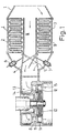
- Fig. 1 illustrates an arrangement by means of which it is possible, in principle, to construct the control system.
- the system 1 for controlling the incoming air is divided into three flow ducts, of which the first one (I) is provided with a heating heat exchanger 2, the second one (11) is provided with a cooling heat exchanger 3, and the third one (III) is a straight flow duct without heat exchanger.
- the temperature of the incoming air is controlled by guiding the air flow partly or completely through either one of the flow ducts I, 11 provided with a heat exchanger 2, 3 by regulating the control gates by means of pneumatic, hydraulic or electric actuating means 6, 7.
- Fig. 1 shows the construction of the air turbine.
- the air flowing into the air turbine is passed into the temperature control unit 1, where the air may flow through three ducts I, II, III.
- the temperature of the air flow is measured after the control unit 1 in the duct 13 passing to the turbine. If the air temperature in the duct 13 is below the desired value, the control gate 4 is opened by the actuating means 6, whereby part of the incoming air flow passes through the heat exchanger 2 that heats the air flow, and thereby the incoming air becomes warm. If the air temperature in the duct 13 is above the desired value, the control gate 5 is opened by the actuating means 7, whereby part of the incoming air flow passes through the heat exchanger 3 that cools the air flow, and thereby the incoming air is cooled.
- the controlling of the temperature of the incoming air takes place by means of a prior-art technique.
- the turbine shown in Figures 1 and 2 as an example is an axial turbine operating with a moderate reaction degree.
- the air turbine consists of a stator 8, whose guide wheel 9 is provided with guide blades 14.
- the other part of the turbine is the rotor 10, whose runner 11 is provided with runner blades 15.
- the guide passages 16 formed between the guide blades 14 are strongly curved in order that the relatively large sub-cooled water drops contained in the air flow passing through the said blades 14 should be separated from the air flow and be decomposed when they strike against the guide blades 14 and are partly solidified or freeze or from wet snow. Adherence of ice or wet snow onto the guide blades 14 is prevented in that the wall temperature in the blades is above the freezing point of water, in which case snow and ice do not adhere to the warm and wet wall but glide along the wall face and are blown off along with the air flow.
- the intermediate space 12 is shaped so that two annular whirls (tori) 18 are formed between the guide wheel 9 and the runner 11 to prevent formation and adherence of ice onto the turbine walls.
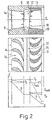
- Figure 2 shows the factual temperature of the flowing air as well as the wall temperatures in the turbine in the stator 8 and in the rotor 10 at the sectional axis of the guide wheel and of the runner.
- the temperature of incoming moist air which is in Fig. 2 denoted with the line To, is adjusted by means of the control unit 1 so that it has a desired value above the freezing point of water.
- the expansion conditions and the reaction degree in the turbine have been chosen so that the wall temperature T s of the turbine in all of the parts of the stator that are in contact with the air flow is clearly, but only slightly, above the temperature range involving a risk of freezing.
- Thereat the wet snow and subcooled water drops formed in the guide passage 16 in the stator on cooling of the moist air flow do not adhere to the guide blades 14 of the stator, and therefore no formation of ice detrimental to the flowing and dangerous for the operation of the turbine takes place.
- the axial dimension of the intermediate space 12 is at least 30%, preferably about 50%, of the axial dimension of the runner blades 15, and that the temperature of the air before theturbine in the duct 13 is within the range of 2 to 10° C, and the temperature between the guide wheel and the runner is within the range of -30to-15°C.
Landscapes
- Engineering & Computer Science (AREA)
- Mechanical Engineering (AREA)
- General Engineering & Computer Science (AREA)
- Chemical & Material Sciences (AREA)
- Combustion & Propulsion (AREA)
- Turbine Rotor Nozzle Sealing (AREA)
Abstract
Description
- The present invention concerns an air turbine in accordance with the preamble of claim 1.
- Such an air turbine can be used, e. g., in heat pumps, refrigeration equipment, air-drying apparatuses, and equivalent.
- Outdoor air always contains larger or smaller quantities of water in one, two or three states. Thus, outdoor air always contains water in gaseous state (as water vapour), but it may additionally contain water in liquid state (as mist, fog, drizzle, rain), or in solid state (as snow, hail). Moreover, water may be present simultaneously in gaseous, liquid and solid states (as so-called mixed cloud).
- When wet or moist air expands rapidly in a curved flow duct from a temperature above the freezing point of water to a temperature considerably below this point, the state of the water contained in the air is changed owing to condensation, sublimation, and/or freezing. All of these changes are based on physical phenomena whose mechanisms are very complicated.
- The drops of water following along with the flow are accelerated far more slowly than air, because the density of water is considerably higher than that of air. Under these circumstances, in curved ducts, drops of water run along entirely different paths, as compared with particles of air.
- The rapid lowering of the temperature resulting from expansion makes all the small drops of water that follow along with the flow subcooled. Sub- cooled water is, however, a liquid in an unstable state, for which reason, in a cold flow of air, these drops solidify to snow flakes, whose number and size increase rapidly.
- If dry flakes of snow or dry particles of ice meet and strike against a cold duct wall whose temperature is below 0° C, no dangerous formation of ice takes place on the duct wall, because the dry snow flakes and the dry particles of ice do not adhere to the cold wall.
- If moist flakes of snow, moist particles of ice or small or large subcooled drops of water meet and strike against a warm duct wall whose temperature is higher than 0° C, dangerous formation of ice does not occur either, for snow or ice does not adhere to a warm and moist wall, but glides along it and is blown off.
- On the contrary, should subcooled drops of water meet and strike against a cold duct wall whose temperature is lower than 0° C, dangerous formation of ice would occur. In such a case, a strong and hard layer of ice would be formed forthwith, and its thickness would increase rapidly. Such formation of ice can take place only within a temperature range of -10° C to 0° C.
- The object of the present invention is to provide an airturbine in which wet or moist air may expand and cool down to temperatures that are considerably lower than the freezing point of water without disturbance or prevention of the operation of the turbine by formation of ice on such faces of turbine parts as are in contact with the flow of air passing through the turbine. Expansion to temperatures that are considerably below the freezing point of water (0° C) is energy-economically interesting.
- With an equal consumption of operating energy, expansion at lower temperatures results in
- - higher heating capacity in a heat pump,
- - higher quantity of air in air-drying apparatuses, etc. as compared with expansion at higher temperatures.
- The operational idea of the invention lies therein that the temperature range (-10° C to 0° C) risky from the point of view of difficult formation of ice is avoided or eliminated and that subcooled drops of water cannot meet or strike against such duct walls whose temperature is lower than 0° C. Thus, all of the parts of the turbine stator that reach contact with the air flow have a temperature slightly but clearly above the dangerous temperature range. On the contrary, the static temperature of the air in the intermediate space between the stator and the rotor, and so also the wall temperature everywhere in the turbine rotor, will be clearly below that dangerous temperature range. It follows from this that dangerous formation of ice cannot occur, neither in the stator nor in the rotor.
- More specifically, the air turbine in accordance with the invention is characterized in what is stated in the characterizing part of claim 1.
- By means of the invention, considerable advantages are obtained. Thus, by means of a turbine in accordance with the invention it is possible to reduce the energy consumption to a considerable extent, which again also reduces the amount of overall investments. Moreover, owing to its nature, the operation of the turbine in accordance with the invention is considerably more reliable than prior-art solutions.
- The invention will be examined in the following in more detail with the aid of the attached drawings.
- Figure 1 illustrates the construction of an air turbine in accordance with the invention and of related equipment for controlling the temperature of the wet or moist air flowing into the turbine.
- Figure 2 is a sectional view of the turbine blades and shows a diagram which illustrates the factual temperature of the air as well as the wall temperature of the turbine in the stator and in the rotor.
- The air turbine subject of the invention consists of a turbine itself as well as of an apparatus by means of which the temperature of the wet or moist air flowing in is controlled. Fig. 1 illustrates an arrangement by means of which it is possible, in principle, to construct the control system. The system 1 for controlling the incoming air is divided into three flow ducts, of which the first one (I) is provided with a
heating heat exchanger 2, the second one (11) is provided with a cooling heat exchanger 3, and the third one (III) is a straight flow duct without heat exchanger. The temperature of the incoming air is controlled by guiding the air flow partly or completely through either one of the flow ducts I, 11 provided with aheat exchanger 2, 3 by regulating the control gates by means of pneumatic, hydraulic or electric actuating means 6, 7. - Fig. 1 shows the construction of the air turbine. The air flowing into the air turbine is passed into the temperature control unit 1, where the air may flow through three ducts I, II, III. The temperature of the air flow is measured after the control unit 1 in the
duct 13 passing to the turbine. If the air temperature in theduct 13 is below the desired value, the control gate 4 is opened by the actuating means 6, whereby part of the incoming air flow passes through theheat exchanger 2 that heats the air flow, and thereby the incoming air becomes warm. If the air temperature in theduct 13 is above the desired value, thecontrol gate 5 is opened by the actuating means 7, whereby part of the incoming air flow passes through the heat exchanger 3 that cools the air flow, and thereby the incoming air is cooled. The controlling of the temperature of the incoming air takes place by means of a prior-art technique. - Regarding its principle of operation, the turbine may be an action turbine or a reaction turbine or a turbine operating with a moderate reaction degree (r = 0.05 to 0.45). The turbine shown in Figures 1 and 2 as an example is an axial turbine operating with a moderate reaction degree.
- The air turbine consists of a
stator 8, whoseguide wheel 9 is provided withguide blades 14. The other part of the turbine is therotor 10, whoserunner 11 is provided withrunner blades 15. Theguide passages 16 formed between theguide blades 14 are strongly curved in order that the relatively large sub-cooled water drops contained in the air flow passing through thesaid blades 14 should be separated from the air flow and be decomposed when they strike against theguide blades 14 and are partly solidified or freeze or from wet snow. Adherence of ice or wet snow onto theguide blades 14 is prevented in that the wall temperature in the blades is above the freezing point of water, in which case snow and ice do not adhere to the warm and wet wall but glide along the wall face and are blown off along with the air flow. - Between the
guide wheel 9 and therunner 11, there is a relatively largeintermediate space 12, in order that the distance passed by the air flow from theguide wheel 9 to therunner 11 should be sufficiently long. This is important in view of the operation of the air turbine, because, even though the temperature of the air flow has been lowered to a level considerably below the freezing point of water after the air flow has passed through theguide passages 16, the wet snow and subcooled water drops formed must have time enough to be frozen before they arrive attherunner 11. Since the cooling taking place in the intermediate space results in the generation of dry snow flakes or dry particles of ice, these do not adhere to the walls of therunner 11 even though the prevailing wall temperature is lower than the freezing point of water, for dry particles of ice do not adhere to a cold wall face. - The
intermediate space 12 is shaped so that two annular whirls (tori) 18 are formed between theguide wheel 9 and therunner 11 to prevent formation and adherence of ice onto the turbine walls. - Figure 2 shows the factual temperature of the flowing air as well as the wall temperatures in the turbine in the
stator 8 and in therotor 10 at the sectional axis of the guide wheel and of the runner. When the figures is examined, the operational idea of the invention comes out, wherein the aim is to construct an air turbine in which formation of ice is prevented within the risky temperature range of -10° C to 0° C and in which contact of subcooled water drops with the walls of the turbine temperature is below 0° C is prevented. - The temperature of incoming moist air, which is in Fig. 2 denoted with the line To, is adjusted by means of the control unit 1 so that it has a desired value above the freezing point of water. The expansion conditions and the reaction degree in the turbine have been chosen so that the wall temperature Ts of the turbine in all of the parts of the stator that are in contact with the air flow is clearly, but only slightly, above the temperature range involving a risk of freezing. Thereat the wet snow and subcooled water drops formed in the
guide passage 16 in the stator on cooling of the moist air flow do not adhere to theguide blades 14 of the stator, and therefore no formation of ice detrimental to the flowing and dangerous for the operation of the turbine takes place. - The static temperature of the air in the intermediate space between the guide wheel and the runner, as well as the turbine wall temperature T,, in all parts of the rotor that are in contact with the air flow, are clearly below the range involving risk of freezing, so that any dry particles of ice formed do not partly melt on the wall faces, thereby permitting adhering of ice particles onto the walls.
- It should be mentioned that the axial dimension of the
intermediate space 12 is at least 30%, preferably about 50%, of the axial dimension of therunner blades 15, and that the temperature of the air before theturbine in theduct 13 is within the range of 2 to 10° C, and the temperature between the guide wheel and the runner is within the range of -30to-15°C. - Within the scope of the invention as defined by the claims, it is also possible to conceive solutions differing from the exemplifying embodiment described above.
Claims (5)
Applications Claiming Priority (2)
| Application Number | Priority Date | Filing Date | Title |
|---|---|---|---|
| FI852282A FI72375C (en) | 1985-06-07 | 1985-06-07 | Air Turbine. |
| FI852282 | 1985-06-07 |
Publications (2)
| Publication Number | Publication Date |
|---|---|
| EP0225356A1 EP0225356A1 (en) | 1987-06-16 |
| EP0225356B1 true EP0225356B1 (en) | 1989-05-24 |
Family
ID=8520953
Family Applications (1)
| Application Number | Title | Priority Date | Filing Date |
|---|---|---|---|
| EP86903396A Expired EP0225356B1 (en) | 1985-06-07 | 1986-06-05 | Air turbine |
Country Status (8)
| Country | Link |
|---|---|
| US (1) | US4747748A (en) |
| EP (1) | EP0225356B1 (en) |
| JP (1) | JPH0754088B2 (en) |
| CA (1) | CA1266619A (en) |
| DE (1) | DE3663559D1 (en) |
| FI (1) | FI72375C (en) |
| SU (1) | SU1567127A3 (en) |
| WO (1) | WO1986007411A1 (en) |
Families Citing this family (10)
| Publication number | Priority date | Publication date | Assignee | Title |
|---|---|---|---|---|
| FI860430A0 (en) * | 1986-01-29 | 1986-01-29 | Imatran Voima Oy | FOERFARANDE OCH ANORDNING FOER UTNYTTJANDE AV VAERMEENERGI SOM FRIGOERS I KYLPROCESS. |
| EP0387362A1 (en) * | 1989-03-12 | 1990-09-19 | Ventilplafon S.A. | Air conditioning system for rooms |
| WO1998015732A1 (en) * | 1996-10-08 | 1998-04-16 | Siemens Aktiengesellschaft | Method for thermoregulating inlet air, and thermostat needed for its application |
| US6593547B1 (en) | 2000-11-30 | 2003-07-15 | Pacific Scientific Electro Kinetics Division | Air gap deicing device |
| US7251951B2 (en) * | 2004-04-16 | 2007-08-07 | Honeywell International, Inc. | Heated sub-freezing airflow diverter |
| GB0813938D0 (en) * | 2008-07-30 | 2008-09-03 | Heat Recovery Solutions Ltd | Heat exchanger |
| US9657844B2 (en) * | 2011-09-14 | 2017-05-23 | Honeywell International Inc. | High temperature aluminum valve components |
| GB2515330B (en) * | 2013-06-20 | 2015-11-04 | Boustead Internat Heaters Ltd | Improvements in waste heat recovery units |
| DE102019101488B4 (en) * | 2019-01-22 | 2021-05-27 | Man Energy Solutions Se | Plant for generating electrical energy |
| AT527677B1 (en) * | 2024-02-19 | 2025-05-15 | Christof Systems Gmbh | Stator for a turbine |
Family Cites Families (7)
| Publication number | Priority date | Publication date | Assignee | Title |
|---|---|---|---|---|
| DE562857C (en) * | 1932-10-29 | Bbc Brown Boveri & Cie | Compressor with downstream turbine for air or gas processing systems | |
| DE418068C (en) * | 1924-07-27 | 1925-09-01 | Kopp & Kausch | Device for preventing ice formation in machines driven by compressed air, in particular compressed air turbines |
| US2415673A (en) * | 1944-10-13 | 1947-02-11 | Gen Electric | Turbine control device |
| US2642721A (en) * | 1948-01-29 | 1953-06-23 | Power Jets Res & Dev Ltd | Closed cycle elastic fluid compressor-turbine plant and control thereof |
| US3109285A (en) * | 1959-08-03 | 1963-11-05 | Boeing Co | Accessory power system for aircraft |
| DE2816984C2 (en) * | 1978-04-19 | 1983-12-22 | Aeg-Telefunken Ag, 1000 Berlin Und 6000 Frankfurt | Device for operating an exhaust gas turbine |
| US4312381A (en) * | 1980-03-27 | 1982-01-26 | Aladdin Heating Corporation | Air flow damping system |
-
1985
- 1985-06-07 FI FI852282A patent/FI72375C/en not_active IP Right Cessation
-
1986
- 1986-06-05 JP JP61503308A patent/JPH0754088B2/en not_active Expired - Lifetime
- 1986-06-05 WO PCT/FI1986/000061 patent/WO1986007411A1/en not_active Ceased
- 1986-06-05 EP EP86903396A patent/EP0225356B1/en not_active Expired
- 1986-06-05 DE DE8686903396T patent/DE3663559D1/en not_active Expired
- 1986-06-05 US US07/030,837 patent/US4747748A/en not_active Expired - Fee Related
- 1986-06-06 CA CA000511042A patent/CA1266619A/en not_active Expired - Fee Related
-
1987
- 1987-02-06 SU SU874028939A patent/SU1567127A3/en active
Also Published As
| Publication number | Publication date |
|---|---|
| FI72375B (en) | 1987-01-30 |
| FI852282A0 (en) | 1985-06-07 |
| JPS63500258A (en) | 1988-01-28 |
| DE3663559D1 (en) | 1989-06-29 |
| CA1266619A (en) | 1990-03-13 |
| EP0225356A1 (en) | 1987-06-16 |
| JPH0754088B2 (en) | 1995-06-07 |
| FI72375C (en) | 1987-05-11 |
| SU1567127A3 (en) | 1990-05-23 |
| US4747748A (en) | 1988-05-31 |
| WO1986007411A1 (en) | 1986-12-18 |
| FI852282L (en) | 1986-12-08 |
Similar Documents
| Publication | Publication Date | Title |
|---|---|---|
| CA1093303A (en) | Efficiency air cycle environmental control system | |
| US4747748A (en) | Air turbine for preventing formation of ice on air exposed turbine parts | |
| US4771612A (en) | Method and apparatus for the utilization of heat energy released in a cooling process of water | |
| CA2044292C (en) | Environmental control system condensing cycle | |
| US5873695A (en) | Steam cooled blade | |
| EP0955449B1 (en) | Gas turbine blade | |
| USRE32100E (en) | Efficiency air cycle environmental control system | |
| US4180373A (en) | Turbine blade | |
| US3716097A (en) | Air condensation plant | |
| PL112859B1 (en) | Air conditioning apparatus | |
| CN112594126A (en) | Wind turbine blade with hot gas anti-icing air film jet hole | |
| CN110374827B (en) | An anti-icing system and method for wind turbine blades | |
| CN113944495A (en) | Mine cooling system | |
| KR101570734B1 (en) | Cooling system using latent heat between ice and water | |
| CN117969005B (en) | A temperature and humidity control system for the main fan motor and frequency converter of an automotive environmental wind tunnel. | |
| CN116624347B (en) | Method, system and device for monitoring icing of fan blade | |
| CN115324665A (en) | Deicing and ice cutting device for expansion machine | |
| CN114777517A (en) | A Circulating Cooling System for Preventing Condenser Inlet Water Temperature from Overcooling | |
| Gray et al. | Preliminary results of cyclical de-icing of a gas-heated airfoil | |
| Stewart Jr et al. | Air temperature depression and potential icing at the inlet of stationary combustion turbines | |
| CN220472372U (en) | Novel structure closed cooling tower | |
| CN218915947U (en) | Frosting-proof buffer balance window for refrigeration house | |
| SU1728616A1 (en) | Method for controlling cooling water working modes | |
| JPS5813262Y2 (en) | air cooling device | |
| McKinnon et al. | Experimental Investigation of External Water-spray Cooling in a Turbojet Engine Utilizing Several Injection Configurations Including Orifices in the Rotor-blade Bases |
Legal Events
| Date | Code | Title | Description |
|---|---|---|---|
| PUAI | Public reference made under article 153(3) epc to a published international application that has entered the european phase |
Free format text: ORIGINAL CODE: 0009012 |
|
| 17P | Request for examination filed |
Effective date: 19870401 |
|
| AK | Designated contracting states |
Kind code of ref document: A1 Designated state(s): CH DE FR GB IT LI SE |
|
| 17Q | First examination report despatched |
Effective date: 19871117 |
|
| GRAA | (expected) grant |
Free format text: ORIGINAL CODE: 0009210 |
|
| AK | Designated contracting states |
Kind code of ref document: B1 Designated state(s): CH DE FR GB IT LI SE |
|
| ITF | It: translation for a ep patent filed | ||
| REF | Corresponds to: |
Ref document number: 3663559 Country of ref document: DE Date of ref document: 19890629 |
|
| ET | Fr: translation filed | ||
| PLBE | No opposition filed within time limit |
Free format text: ORIGINAL CODE: 0009261 |
|
| STAA | Information on the status of an ep patent application or granted ep patent |
Free format text: STATUS: NO OPPOSITION FILED WITHIN TIME LIMIT |
|
| 26N | No opposition filed | ||
| ITTA | It: last paid annual fee | ||
| PGFP | Annual fee paid to national office [announced via postgrant information from national office to epo] |
Ref country code: DE Payment date: 19940514 Year of fee payment: 9 |
|
| PGFP | Annual fee paid to national office [announced via postgrant information from national office to epo] |
Ref country code: GB Payment date: 19940516 Year of fee payment: 9 Ref country code: CH Payment date: 19940516 Year of fee payment: 9 |
|
| PGFP | Annual fee paid to national office [announced via postgrant information from national office to epo] |
Ref country code: FR Payment date: 19940519 Year of fee payment: 9 |
|
| PGFP | Annual fee paid to national office [announced via postgrant information from national office to epo] |
Ref country code: SE Payment date: 19940524 Year of fee payment: 9 |
|
| EAL | Se: european patent in force in sweden |
Ref document number: 86903396.9 |
|
| PG25 | Lapsed in a contracting state [announced via postgrant information from national office to epo] |
Ref country code: GB Effective date: 19950605 |
|
| PG25 | Lapsed in a contracting state [announced via postgrant information from national office to epo] |
Ref country code: SE Effective date: 19950606 |
|
| PG25 | Lapsed in a contracting state [announced via postgrant information from national office to epo] |
Ref country code: LI Effective date: 19950630 Ref country code: CH Effective date: 19950630 |
|
| GBPC | Gb: european patent ceased through non-payment of renewal fee |
Effective date: 19950605 |
|
| PG25 | Lapsed in a contracting state [announced via postgrant information from national office to epo] |
Ref country code: FR Effective date: 19960229 |
|
| REG | Reference to a national code |
Ref country code: CH Ref legal event code: PL |
|
| PG25 | Lapsed in a contracting state [announced via postgrant information from national office to epo] |
Ref country code: DE Effective date: 19960301 |
|
| EUG | Se: european patent has lapsed |
Ref document number: 86903396.9 |
|
| REG | Reference to a national code |
Ref country code: FR Ref legal event code: ST |
|
| PG25 | Lapsed in a contracting state [announced via postgrant information from national office to epo] |
Ref country code: IT Free format text: LAPSE BECAUSE OF NON-PAYMENT OF DUE FEES;WARNING: LAPSES OF ITALIAN PATENTS WITH EFFECTIVE DATE BEFORE 2007 MAY HAVE OCCURRED AT ANY TIME BEFORE 2007. THE CORRECT EFFECTIVE DATE MAY BE DIFFERENT FROM THE ONE RECORDED. Effective date: 20050605 |