EP0224240B1 - Apparatus for the control of an installation for the manufacturing of extruded sections - Google Patents
Apparatus for the control of an installation for the manufacturing of extruded sections Download PDFInfo
- Publication number
- EP0224240B1 EP0224240B1 EP86116333A EP86116333A EP0224240B1 EP 0224240 B1 EP0224240 B1 EP 0224240B1 EP 86116333 A EP86116333 A EP 86116333A EP 86116333 A EP86116333 A EP 86116333A EP 0224240 B1 EP0224240 B1 EP 0224240B1
- Authority
- EP
- European Patent Office
- Prior art keywords
- light
- field
- till
- fields
- corner
- Prior art date
- Legal status (The legal status is an assumption and is not a legal conclusion. Google has not performed a legal analysis and makes no representation as to the accuracy of the status listed.)
- Expired - Lifetime
Links
Images


Classifications
-
- B—PERFORMING OPERATIONS; TRANSPORTING
- B29—WORKING OF PLASTICS; WORKING OF SUBSTANCES IN A PLASTIC STATE IN GENERAL
- B29C—SHAPING OR JOINING OF PLASTICS; SHAPING OF MATERIAL IN A PLASTIC STATE, NOT OTHERWISE PROVIDED FOR; AFTER-TREATMENT OF THE SHAPED PRODUCTS, e.g. REPAIRING
- B29C55/00—Shaping by stretching, e.g. drawing through a die; Apparatus therefor
- B29C55/30—Drawing through a die
-
- B—PERFORMING OPERATIONS; TRANSPORTING
- B29—WORKING OF PLASTICS; WORKING OF SUBSTANCES IN A PLASTIC STATE IN GENERAL
- B29C—SHAPING OR JOINING OF PLASTICS; SHAPING OF MATERIAL IN A PLASTIC STATE, NOT OTHERWISE PROVIDED FOR; AFTER-TREATMENT OF THE SHAPED PRODUCTS, e.g. REPAIRING
- B29C48/00—Extrusion moulding, i.e. expressing the moulding material through a die or nozzle which imparts the desired form; Apparatus therefor
- B29C48/03—Extrusion moulding, i.e. expressing the moulding material through a die or nozzle which imparts the desired form; Apparatus therefor characterised by the shape of the extruded material at extrusion
- B29C48/05—Filamentary, e.g. strands
-
- B—PERFORMING OPERATIONS; TRANSPORTING
- B29—WORKING OF PLASTICS; WORKING OF SUBSTANCES IN A PLASTIC STATE IN GENERAL
- B29C—SHAPING OR JOINING OF PLASTICS; SHAPING OF MATERIAL IN A PLASTIC STATE, NOT OTHERWISE PROVIDED FOR; AFTER-TREATMENT OF THE SHAPED PRODUCTS, e.g. REPAIRING
- B29C48/00—Extrusion moulding, i.e. expressing the moulding material through a die or nozzle which imparts the desired form; Apparatus therefor
- B29C48/03—Extrusion moulding, i.e. expressing the moulding material through a die or nozzle which imparts the desired form; Apparatus therefor characterised by the shape of the extruded material at extrusion
- B29C48/09—Articles with cross-sections having partially or fully enclosed cavities, e.g. pipes or channels
- B29C48/10—Articles with cross-sections having partially or fully enclosed cavities, e.g. pipes or channels flexible, e.g. blown foils
-
- B—PERFORMING OPERATIONS; TRANSPORTING
- B29—WORKING OF PLASTICS; WORKING OF SUBSTANCES IN A PLASTIC STATE IN GENERAL
- B29C—SHAPING OR JOINING OF PLASTICS; SHAPING OF MATERIAL IN A PLASTIC STATE, NOT OTHERWISE PROVIDED FOR; AFTER-TREATMENT OF THE SHAPED PRODUCTS, e.g. REPAIRING
- B29C48/00—Extrusion moulding, i.e. expressing the moulding material through a die or nozzle which imparts the desired form; Apparatus therefor
- B29C48/25—Component parts, details or accessories; Auxiliary operations
- B29C48/88—Thermal treatment of the stream of extruded material, e.g. cooling
- B29C48/90—Thermal treatment of the stream of extruded material, e.g. cooling with calibration or sizing, i.e. combined with fixing or setting of the final dimensions of the extruded article
- B29C48/908—Thermal treatment of the stream of extruded material, e.g. cooling with calibration or sizing, i.e. combined with fixing or setting of the final dimensions of the extruded article characterised by calibrator surface, e.g. structure or holes for lubrication, cooling or venting
-
- B—PERFORMING OPERATIONS; TRANSPORTING
- B29—WORKING OF PLASTICS; WORKING OF SUBSTANCES IN A PLASTIC STATE IN GENERAL
- B29C—SHAPING OR JOINING OF PLASTICS; SHAPING OF MATERIAL IN A PLASTIC STATE, NOT OTHERWISE PROVIDED FOR; AFTER-TREATMENT OF THE SHAPED PRODUCTS, e.g. REPAIRING
- B29C48/00—Extrusion moulding, i.e. expressing the moulding material through a die or nozzle which imparts the desired form; Apparatus therefor
- B29C48/25—Component parts, details or accessories; Auxiliary operations
- B29C48/88—Thermal treatment of the stream of extruded material, e.g. cooling
- B29C48/919—Thermal treatment of the stream of extruded material, e.g. cooling using a bath, e.g. extruding into an open bath to coagulate or cool the material
-
- B—PERFORMING OPERATIONS; TRANSPORTING
- B29—WORKING OF PLASTICS; WORKING OF SUBSTANCES IN A PLASTIC STATE IN GENERAL
- B29C—SHAPING OR JOINING OF PLASTICS; SHAPING OF MATERIAL IN A PLASTIC STATE, NOT OTHERWISE PROVIDED FOR; AFTER-TREATMENT OF THE SHAPED PRODUCTS, e.g. REPAIRING
- B29C48/00—Extrusion moulding, i.e. expressing the moulding material through a die or nozzle which imparts the desired form; Apparatus therefor
- B29C48/25—Component parts, details or accessories; Auxiliary operations
- B29C48/92—Measuring, controlling or regulating
-
- B—PERFORMING OPERATIONS; TRANSPORTING
- B29—WORKING OF PLASTICS; WORKING OF SUBSTANCES IN A PLASTIC STATE IN GENERAL
- B29C—SHAPING OR JOINING OF PLASTICS; SHAPING OF MATERIAL IN A PLASTIC STATE, NOT OTHERWISE PROVIDED FOR; AFTER-TREATMENT OF THE SHAPED PRODUCTS, e.g. REPAIRING
- B29C2948/00—Indexing scheme relating to extrusion moulding
- B29C2948/92—Measuring, controlling or regulating
- B29C2948/92009—Measured parameter
- B29C2948/92076—Position, e.g. linear or angular
-
- B—PERFORMING OPERATIONS; TRANSPORTING
- B29—WORKING OF PLASTICS; WORKING OF SUBSTANCES IN A PLASTIC STATE IN GENERAL
- B29C—SHAPING OR JOINING OF PLASTICS; SHAPING OF MATERIAL IN A PLASTIC STATE, NOT OTHERWISE PROVIDED FOR; AFTER-TREATMENT OF THE SHAPED PRODUCTS, e.g. REPAIRING
- B29C2948/00—Indexing scheme relating to extrusion moulding
- B29C2948/92—Measuring, controlling or regulating
- B29C2948/92323—Location or phase of measurement
- B29C2948/92428—Calibration, after-treatment, or cooling zone
-
- B—PERFORMING OPERATIONS; TRANSPORTING
- B29—WORKING OF PLASTICS; WORKING OF SUBSTANCES IN A PLASTIC STATE IN GENERAL
- B29C—SHAPING OR JOINING OF PLASTICS; SHAPING OF MATERIAL IN A PLASTIC STATE, NOT OTHERWISE PROVIDED FOR; AFTER-TREATMENT OF THE SHAPED PRODUCTS, e.g. REPAIRING
- B29C2948/00—Indexing scheme relating to extrusion moulding
- B29C2948/92—Measuring, controlling or regulating
- B29C2948/92504—Controlled parameter
- B29C2948/9258—Velocity
- B29C2948/9259—Angular velocity
-
- B—PERFORMING OPERATIONS; TRANSPORTING
- B29—WORKING OF PLASTICS; WORKING OF SUBSTANCES IN A PLASTIC STATE IN GENERAL
- B29C—SHAPING OR JOINING OF PLASTICS; SHAPING OF MATERIAL IN A PLASTIC STATE, NOT OTHERWISE PROVIDED FOR; AFTER-TREATMENT OF THE SHAPED PRODUCTS, e.g. REPAIRING
- B29C2948/00—Indexing scheme relating to extrusion moulding
- B29C2948/92—Measuring, controlling or regulating
- B29C2948/92819—Location or phase of control
- B29C2948/92857—Extrusion unit
- B29C2948/92876—Feeding, melting, plasticising or pumping zones, e.g. the melt itself
- B29C2948/92885—Screw or gear
-
- B—PERFORMING OPERATIONS; TRANSPORTING
- B29—WORKING OF PLASTICS; WORKING OF SUBSTANCES IN A PLASTIC STATE IN GENERAL
- B29C—SHAPING OR JOINING OF PLASTICS; SHAPING OF MATERIAL IN A PLASTIC STATE, NOT OTHERWISE PROVIDED FOR; AFTER-TREATMENT OF THE SHAPED PRODUCTS, e.g. REPAIRING
- B29C2948/00—Indexing scheme relating to extrusion moulding
- B29C2948/92—Measuring, controlling or regulating
- B29C2948/92819—Location or phase of control
- B29C2948/92933—Conveying, transporting or storage of articles
-
- B—PERFORMING OPERATIONS; TRANSPORTING
- B29—WORKING OF PLASTICS; WORKING OF SUBSTANCES IN A PLASTIC STATE IN GENERAL
- B29C—SHAPING OR JOINING OF PLASTICS; SHAPING OF MATERIAL IN A PLASTIC STATE, NOT OTHERWISE PROVIDED FOR; AFTER-TREATMENT OF THE SHAPED PRODUCTS, e.g. REPAIRING
- B29C48/00—Extrusion moulding, i.e. expressing the moulding material through a die or nozzle which imparts the desired form; Apparatus therefor
- B29C48/25—Component parts, details or accessories; Auxiliary operations
- B29C48/88—Thermal treatment of the stream of extruded material, e.g. cooling
- B29C48/90—Thermal treatment of the stream of extruded material, e.g. cooling with calibration or sizing, i.e. combined with fixing or setting of the final dimensions of the extruded article
- B29C48/904—Thermal treatment of the stream of extruded material, e.g. cooling with calibration or sizing, i.e. combined with fixing or setting of the final dimensions of the extruded article using dry calibration, i.e. no quenching tank, e.g. with water spray for cooling or lubrication
-
- B—PERFORMING OPERATIONS; TRANSPORTING
- B29—WORKING OF PLASTICS; WORKING OF SUBSTANCES IN A PLASTIC STATE IN GENERAL
- B29C—SHAPING OR JOINING OF PLASTICS; SHAPING OF MATERIAL IN A PLASTIC STATE, NOT OTHERWISE PROVIDED FOR; AFTER-TREATMENT OF THE SHAPED PRODUCTS, e.g. REPAIRING
- B29C48/00—Extrusion moulding, i.e. expressing the moulding material through a die or nozzle which imparts the desired form; Apparatus therefor
- B29C48/25—Component parts, details or accessories; Auxiliary operations
- B29C48/88—Thermal treatment of the stream of extruded material, e.g. cooling
- B29C48/911—Cooling
- B29C48/9115—Cooling of hollow articles
- B29C48/912—Cooling of hollow articles of tubular films
- B29C48/913—Cooling of hollow articles of tubular films externally
Definitions
- the invention relates to a method and a device for controlling a system for the production of extruded profiles, in particular plastic profiles or the like, which contains an extrusion tool and a downstream calibration tool in the material flow, with a measuring head for the contactless optical detection of a material jam or material swelling between the Extrusion nozzle and the calibration tool, which has a light-transmitting surface and a light-receiving surface in a spaced-apart arrangement, at least a plurality of light-guiding elements ending at the latter.
- extrusion dies are used, for example in the form of an extruder with an associated extruder nozzle.
- the stream of material emerging from the extrusion tool is fed to a calibration tool which determines the final external shape of the extrusion profile.
- the calibration tool can have an opening, the cross section of which essentially corresponds to that of the extruder nozzle or is somewhat smaller in order to ensure a shaping effect.
- the space between the extruder nozzle and the calibration tool there is a swelling of material in the area of the extruder nozzle mouth and a material jam in front of the calibration tool.
- the object of the invention serves to optically detect this swelling or this jam for the purpose of controlling the production system.
- a cooling device and a device for pulling off the extruded profile usually follow downstream of the calibration tool.
- the formation of the material swelling or the material jam before the input of the calibration tool can be controlled on the one hand on the basis of the speed at which the extrusion tool works; in particular, the speed of the extruder screw can be regulated in a nozzle extruder.
- the speed at which the trigger device works there is the possibility of influencing the speed at which the trigger device works. In both cases, it is important to record the current size of the material swelling or the material jam before the input of the calibration tool and to compare it with a predetermined target value for the material swelling or the material jam in order to obtain a control signal.
- DE-OS 24 33 242 a device for detecting the current material jam before the entrance of a calibration tool is known, in which a mechanical scanning of the extrusion profile emerging from the extrusion tool takes place.
- DE-OS 32 34 126 proposes a contactless optical detection of the material jam, in which an edge of the extruded profile lies in front of the calibration tool in the beam path between a light emitting surface and a light receiving surface and the light absorption is measured in the extruded profile.
- light transmission surface by means of a plurality of optical fibers ending thereon, which guide the light from a remotely arranged light source, and also to have a plurality of optical fibers end on the light receiving surface, through which the incident light reaches a photodetector.
- light is to be understood as electromagnetic radiation from the visible and neighboring spectral ranges. Infrared radiation is preferably used, which may be detected with a photodiode upstream of a filter. Glass fibers can be used as optical fibers.
- FR-PS 2 346 680 a device for measuring the lateral deviation of a web that migrates transversely to the direction of movement is known.
- This device requires two compensation fields to measure the light transmission on the web, which is used as a difference measurement.
- the cross-section or the shape dimension of an extrudate cannot be recorded with this device, since it can only be used functionally to determine the position of flat objects, such as foils or paper webs.
- DE-A 2 913 410 discloses a light-conducting electrical measuring device for value-based detection of a position of an edge of a sheet on a surface of a sheet-fed rotary printing press. With such a measuring device, only a very imprecise digital measurement is possible. Intermediate steps, i.e. an analog measurement without partial jumps to obtain measurement data, cannot be carried out with this device.
- the object of the invention is to provide a method and a device of the type mentioned which, with an uncomplicated structure, enable a precise, rapid detection of the position of an edge of the extruded profile in the material swelling behind the extruder nozzle or in the material jam in front of the call tool.
- the method according to the invention and the proposed device offers all the advantages of the contactless optical detection of the material swelling behind the extruder nozzle or the material jam in front of the calibration tool.
- the device according to the invention is suitable for detecting the swelling of material directly behind the extruder nozzle in the production of profiles from soft plastics, for example from soft PVC, which was not possible in the conventional devices which rely on material contact, since in the production of soft plastic extrudates no calibration can be used.
- the measurement is carried out in particular without mechanical influence on the extruded profile. It is insensitive to external influences such as vibrations, dust etc., and it enables a robust, largely maintenance-free construction.
- optical fiber optics enables the Attach the light emitting and receiving surface in the immediate vicinity of the material swelling to be detected or the material jam behind the extruder nozzle or directly in front of the entrance of the calibration tool, which minimizes possible interference.
- the measuring head can be kept very narrow so that it also fits into small gaps between the extrusion tool and the calibration tool.
- the light transmitter and detector can be accommodated at some distance from the material swelling or the material jam without spatial constriction, which is also advantageous for temperature reasons. In plastic extrusion technology, temperatures up to approx. 380 ° C can prevail in front of the calibration tool. Suitable light-guiding elements easily withstand this, while the more temperature-sensitive light transmitter and detector arrangement should preferably be located at a cooler location at some distance.
- the inventive division of the light-receiving surface into several fields, each with a plurality of light-guiding elements, enables a quick, precise position detection of an edge of the extruded profile located in the area of material swelling or material jam.
- a logical yes / no signal or digital signal you can first identify the field into which the edge falls, and thus obtain rough information on the size of the material swelling or material jam, based on which you can quickly see strong fluctuations in the swelling or jam can fix.
- the plurality of individual light guide element ends in each field makes it possible to derive a quasi-analog signal for the position of the edge within the field. It is thus possible to precisely determine the edge position and, under substantially stationary operating conditions, to precisely adjust the material swelling or the material jam to the desired setpoint.
- the fields of the light receiving surface can have a rectangular layout and directly adjoin one another. Two parallel rows of fields are preferably arranged next to one another and offset by half a field length. As a result of this staggering of fields, there is always a field in the central area of which the edge of the extruded profile to be detected falls; Due to the field boundaries, there are no gaps or blind spots in the detection area. Furthermore, two logical signals are obtained, each of which identifies a field of the neighboring lines into which the edge of the extruded profile to be measured falls. On the basis of these two signals, a rough position measurement of the edge with the accuracy of half a field division is possible.
- the light receiving surface can contain a compensation field, preferably spaced apart from the other fields, at the level of which no edge of the extruded profile comes to lie during operation, and which serves to detect a reference level of the light intensity.
- a compensation field preferably spaced apart from the other fields, at the level of which no edge of the extruded profile comes to lie during operation, and which serves to detect a reference level of the light intensity.
- fluctuations in the emitted and detected light intensity can be corrected which are not caused by the material swelling or the material jam.
- this compensates for a changing optical damping that occurs when the light guide elements move or deform.
- there is a compensation of fluctuations in the intensity of the light transmitter and the age-related deterioration of the light transmitter and light receiver and last but not least, the optical absorption of coatings, e.g. Compensate for dust on the light emitting and receiving surface.
- the device according to the invention has a high sensitivity and is not susceptible to interference.
- it is also suitable for capturing extruded profiles made of translucent or translucent material, taking into account the different absorption behavior of these materials in different spectral ranges by choosing a suitable light wavelength for the measurement. Further use is made of the fact that the extruded profiles have a greater optical density in the edge area. This technological advance is surprising and volatile in nature.
- the light emitting surface can have an elongated rectangular shape and approximately the same size as the light receiving surface including the compensation field. In this way, good illumination of the light receiving surface is achieved with little design effort.
- FIG. 1 shows schematically the section of a plant for the production of extruded profiles made of plastic.
- An extrusion die 20 can be seen in the form of a die extruder, from the die 22 of which an extruded profile 24 emerges which is shaped in accordance with the die mouth.
- the extruded profile 24 can be a solid profile or a hollow profile of any layout.
- the extruded profile 24 is calibrated in a calibration tool 26 and thereby brought to its final external dimension.
- the calibration tool 26 has an opening which is usually designed essentially in accordance with the nozzle mouth and is possibly somewhat smaller in cross section.
- a cooling section 28 connects to the calibration tool 26.
- a withdrawal device 30 can be seen, which withdraws the extruded profile 24 from the calibration tool 26 and usually transfers it to a cutting and stacking device.
- the extruded extruded profile 24 forms behind the Extruder nozzle 22 a material swell A and before entering the calibration tool 26 a material jam 32.
- a controller with a measuring head 34 is used for this purpose, which is arranged, for example, immediately behind the extruder nozzle or immediately in front of the input of the calibration tool 26. With the measuring head 34, the swelling A which is currently developing or the material dust 32 is detected optically without contact.
- a corresponding measured value of the measuring head 34 is compared with a predetermined target value which corresponds to the desired optimal setting of the material swelling A or the material jam 32, and a corresponding control signal is derived.
- the latter serves to influence suitable operating parameters of the system in order to increase or decrease the actual value of the material swelling A or the material jam 32; in particular, the speed of an extruder screw in the extrusion die 20 and / or the transport speed of the take-off device 30 can be changed.
- the measuring head 34 is connected to a housing 38 via a light guide cable 36.
- the housing 38 contains a light transmitter and a light receiver.
- electromagnetic radiation in the visible spectral range and neighboring spectral ranges i.e. Infrared radiation and ultraviolet radiation can be understood.
- Infrared radiation is preferred.
- uncomplicated radiation sources in particular in the form of light-emitting diodes and lasers, and uncomplicated detectors, for example in the form of photodiodes.
- Infrared radiation can be guided through a conventional optical fiber optic, which has the advantage of good temperature resistance.
- the measuring head 34 has a flat part 40 of rectangular outline, at one end of which there is a cuboid-shaped extension 42.
- the light guide cable 36 enters this at 44.
- the approach 42 is provided with a blind threaded bore 46, or the like for mounting the measuring head 34 on a tripod rod. serves. Further fastening points 48 for the direct attachment of the measuring head 34 to the nozzle 22 or the calibration tool 26 are provided in the area of the flat part 40.
- a rectangular incision 50 is provided on the side, through which the measuring head 34 acquires a fork shape.
- a large number of individual elements of the light guide cable 36 end at the surfaces. The elements are guided from the housing entry surface 44 through the flat part 40 to light emitting surfaces 52 or light receiving surfaces 54, and they can in particular be embedded in the flat part 40.
- the elements terminating at the light emitting surface 52 carry light that they receive from the light emitter in the housing 38; this light is emitted at the ends of the elements towards the light receiving surface 54.
- the elements ending there absorb light and guide it to the light detector in the housing 38, it being possible for a filter to be switched on at a suitable point, in particular immediately in front of the light detector.
- a filter can be used to switch off daylight influences, such as fluctuations in ambient light brightness, etc., which results in a correspondingly increased measurement accuracy.
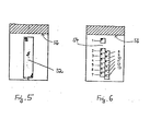
- Figure 5 shows a plan view of the light emitting surface 52. This has an elongated rectangular plan, and it is continuously covered with ends of light guide elements.
- FIG. 6 shows a corresponding top view of the light receiving surface 54. This is divided into a plurality of individual fields, at each of which a plurality of light guide elements end. The fields are square. Near the back 56 of the incision 50 is a single field 1, which is referred to below as the compensation field.
- the compensation field 1 is colinear and at some distance from a row of fields 2, 3, 4, 5, 6, 7, which directly adjoin one another. Directly next to this line is a second line of fields 8, 9, 10, 11, 12, 13, which also directly adjoin one another and are offset by half a field length from fields 2, 3, 4, 5, 6, 7.
- a rectangle enclosing all of the fields 1 to 13 has approximately the same size as the light emitting surface 52.
- the light emitting surface 52 and the light receiving surface 54 form a light barrier which detects an edge of the extruded profile in the area of the material swelling or the material jam 32 in front of the calibration tool 26 during operation.
- the edge comes to lie at the height of the fields 2 to 13, while the compensation field 1 receives a light intensity that is not influenced by the material flow.
- This gives a differential signal which allows fluctuations in the light intensity, aging-related deterioration of the light transmitter or light detector to compensate for optical absorption by a coating which is reflected on the light-transmitting surface 52 or the light-receiving surface 54, etc.
- a first signal is obtained which identifies the field at the level of which the edge of the extruded profile to be detected lies. Due to the staggering of fields 2 to 7 and 8 to 13, there is always a field in the middle of which the edge lies. Normally, one field is identified in each of the two field rows 2 to 7 and 8 to 13, at the level of which the profile edge lies.
- the staggering of the fields allows a grid-based position determination with the accuracy of half a field length. Fast signal processing is possible because a logical yes / no signal or digital signal is sufficient to identify the fields.
- a second signal is derived for fine measurement of the profile edge height, which is characteristic of the height of the profile edge within an identified field. This signal is obtained on the basis of the different light intensity at the light guide elements that end at the field in question.
Landscapes
- Engineering & Computer Science (AREA)
- Mechanical Engineering (AREA)
- Physics & Mathematics (AREA)
- Thermal Sciences (AREA)
- Extrusion Moulding Of Plastics Or The Like (AREA)
- Supports For Plants (AREA)
- Breeding Of Plants And Reproduction By Means Of Culturing (AREA)
- Agricultural Chemicals And Associated Chemicals (AREA)
Abstract
Description
Die Erfindung betrifft ein Verfahren und eine Vorrichtung zur Steuerung einer einer Anlage für die Herstellung von Strangprofilen, insbesondere Kunststoffprofilen oder dergleichen, die ein Strangpreßwerkzeug und ein diesem im Materialstrom nachgeordnetes Kalibrierwerkzeug enthält, mit einem Meßkopf zur berührungslosen optischen Erfassung eines Materialstaus bzw. Materialaufquellung zwischen der Extrusionsdüse und dem Kalibrierwerkzeug, der in beabstandet einander gegenüberliegender Anordnung eine Lichtsendefläche und einen Lichtempfangsfläche aufweist, wobei wenigstens an letzterer eine Mehrzahl von Lichtleitelementen enden.The invention relates to a method and a device for controlling a system for the production of extruded profiles, in particular plastic profiles or the like, which contains an extrusion tool and a downstream calibration tool in the material flow, with a measuring head for the contactless optical detection of a material jam or material swelling between the Extrusion nozzle and the calibration tool, which has a light-transmitting surface and a light-receiving surface in a spaced-apart arrangement, at least a plurality of light-guiding elements ending at the latter.
Zur Herstellung von Strangpreßprofilen werden Strangpreßwerkzeuge beispielsweise in Form eines Extruders mit zugehöriger Extruderdüse verwendet. Der aus dem Strangpreßwerkzeug austretende Materialstrom wird einem Kalibrierwerkzeug zugeleitet, das die endgültige äußere Form des Strangprofils bestimmt.For the production of extruded profiles, extrusion dies are used, for example in the form of an extruder with an associated extruder nozzle. The stream of material emerging from the extrusion tool is fed to a calibration tool which determines the final external shape of the extrusion profile.
Insbesondere kann das Kalibrierwerkzeug eine Öffnung haben, deren Querschnitt im wesentlichen dem der Extruderdüse entspricht oder etwas geringer ist, um eine Formgebungswirkung zu gewährleisten. Im Zwischenraum zwischen der Extruderdüse und dem Kalibrierwerkzeug findet eine Materialaufquellung im Bereich der Extruderdüsenmündung und ein Materialstau vor dem Kalibrierwerkzeug statt.In particular, the calibration tool can have an opening, the cross section of which essentially corresponds to that of the extruder nozzle or is somewhat smaller in order to ensure a shaping effect. In the space between the extruder nozzle and the calibration tool, there is a swelling of material in the area of the extruder nozzle mouth and a material jam in front of the calibration tool.
Der Erfindungsgegenstand dient zur optischen Erfassung dieser Aufquellung bzw. dieses Staus zum Zwecke der Steuerung der Herstellungsanlage.The object of the invention serves to optically detect this swelling or this jam for the purpose of controlling the production system.
Stromab vom Kalibrierwerkzeug schließt sich üblicherweise eine Kühleinrichtung und eine Einrichtung zum Abziehen des Strangprofils an. Die Ausbildung der Materialquellung bzw. des Materialstaus vor dem Eingang des Kalibrierwerkzeugs kann zum einen anhand der Geschwindigkeit gesteuert werden, mit der das Strangpreßwerkzeug arbeitet; insbesondere läßt sich die Drehzahl der Extruderschnecke in einem Düsenextruder regeln. Zum anderen besteht die möglichkeit, die Geschwindigkeit zu beeinflussen, mit der die Abzugsvorrichtung arbeitet. In beiden Fällen gilt es, die momentane Größe der Materialaufquellung bzw. des Materialstaus vor dem Eingang des Kalibrierwerkzeugs zu erfassen und mit einem vorgegebenen Sollwert für die Materialaufquellung bzw. den Materialstau zu vergleichen, um so ein Regelsignal zu gewinnen.A cooling device and a device for pulling off the extruded profile usually follow downstream of the calibration tool. The formation of the material swelling or the material jam before the input of the calibration tool can be controlled on the one hand on the basis of the speed at which the extrusion tool works; in particular, the speed of the extruder screw can be regulated in a nozzle extruder. On the other hand, there is the possibility of influencing the speed at which the trigger device works. In both cases, it is important to record the current size of the material swelling or the material jam before the input of the calibration tool and to compare it with a predetermined target value for the material swelling or the material jam in order to obtain a control signal.
Aus der DE-OS 24 33 242 ist eine Vorrichtung zur Erfassung des momentanen Materialstaus vor dem Eingang eines Kalibrierwerkzeugs bekannt, bei der eine mechanische Abtastung des aus dem Strangpreßwerkzeug austretenden Strangprofils erfolgt. In der DE-OS 32 34 126 wird eine berührungslose optische Erfassung des Materialstaus vorgeschlagen, bei der eine Kante des Strangprofils vor dem Kalibrierwerkzeug im Strahlengang zwischen einer Lichtsendefläche und einer Lichtempfangsfläche liegt und eine Messung der Lichtabsorbtion in dem Strangprofil erfolgt. Es wurde auch bereits vorgeschlagen, eine Lichtsendefläche durch eine Mehrzahl darauf endender Lichtleitfasern zu realisieren, die das Licht einer entfernt angeordneten Lichtquelle führen, und auch auf der Lichtempfangsfläche eine Mehrzahl von Lichtleitfasern enden zu lassen, durch die das auftreffende Licht an einen Fotodetektor gelangt. Unter Licht ist in diesem Zusammenhang elektromagnetische Strahlung aus den sichtbaren und benachbarten Spektralbereichen zu verstehen. Vorzugsweise findet Infrarotstrahlung Verwendung, die gegebenenfalls unter Vorschaltung eines Filters mit einer Fotodiode detektiert wird. Als Lichtleitfasern können Glasfasern zum Einsatz kommen.From DE-OS 24 33 242 a device for detecting the current material jam before the entrance of a calibration tool is known, in which a mechanical scanning of the extrusion profile emerging from the extrusion tool takes place. DE-OS 32 34 126 proposes a contactless optical detection of the material jam, in which an edge of the extruded profile lies in front of the calibration tool in the beam path between a light emitting surface and a light receiving surface and the light absorption is measured in the extruded profile. It has also already been proposed to implement a light transmission surface by means of a plurality of optical fibers ending thereon, which guide the light from a remotely arranged light source, and also to have a plurality of optical fibers end on the light receiving surface, through which the incident light reaches a photodetector. In this context, light is to be understood as electromagnetic radiation from the visible and neighboring spectral ranges. Infrared radiation is preferably used, which may be detected with a photodiode upstream of a filter. Glass fibers can be used as optical fibers.
Aus der FR-PS 2 346 680 ist eine Vorrichtung zur Messung der seitlichen Abweichung einer quer zur Bewegungsrichtung auswandernden Bahn bekannt. Diese Vorrichtung benötigt zwei Kompensationsfelder um bei der Bahn die Lichtdurchlässigkeit zu messen, die als Differenzmessung herangezogen wird. Eine Erfassung des Querschnitts bzw. der Formdimension eines Extrudates kann mit dieser Vorrichtung nicht vorgenommen werden, da diese funktionell nur zur Feststellung der Lage von flächigen Objekten, wie z.B.ßFolien oder Papierbahnen benutzt werden kann.From FR-
Aus der DE-A 2 913 410 ist eine lichtleitelektrische Meßeinrichtung zur wertmäßigen Erfassung einer Lage einer Kante eines Bogens auf einer Fläche einer Bogenrotationsdruckmaschine bekannt. Mit einer solchen Meßeinrichtung ist lediglich eine sehr ungenaue digitale Messung möglich. Zwischenschritte, also eine Analogmessung ohne Teilsprünge zur Gewinnung von Meßdaten können mit dieser Einrichtung nicht vorgenommen werden.DE-A 2 913 410 discloses a light-conducting electrical measuring device for value-based detection of a position of an edge of a sheet on a surface of a sheet-fed rotary printing press. With such a measuring device, only a very imprecise digital measurement is possible. Intermediate steps, i.e. an analog measurement without partial jumps to obtain measurement data, cannot be carried out with this device.
Aufgabe der Erfindung ist es, ein Verfahren und eine Vorrichtung der genannten Art anzugeben, die bei unaufwendigem Aufbau eine präzise, schnelle Erfassung der Position einer Kante des Strangprofils in der Materialaufquellung hinter der Extruderdüse bzw. im Materialstau vor dem Kallbrierwerkzeug ermöglicht.The object of the invention is to provide a method and a device of the type mentioned which, with an uncomplicated structure, enable a precise, rapid detection of the position of an edge of the extruded profile in the material swelling behind the extruder nozzle or in the material jam in front of the call tool.
Diese Aufgabe wird durch ein Verfahren gemäß des Anspruchs 1 und einer Vorrichtung zur Durchführung des Verfahrens gemäß des Anspruchs 2 gelöst. Besondere Ausführungsmerkmale sind in den Unteransprüchen gekennzeichnet.This object is achieved by a method according to
Das erfindungsgemäße Verfahren und die vorgeschlagene Vorrichtung bietet alle Vorteile der berührungslosen optischen Erfassung der Materialquellung hinter der Extruderdüse bzw. des Materialstaus vor dem Kalibrierwerkzeug. Insbesondere eignet sich die erfindungsgemäße Vorrichtung zum Erfassen der Materialaufquellung direkt hinter der Extruderdüse bei der Herstellung von Profilen aus weichen Kunststoffen, beispielsweise aus Weich-PVC, was bei der herkömmlichen, auf Materialberührung angewiesenen Geräten nicht möglich war, da bei der Herstellung von Weichkunststoff-Extrudaten keine Kalibrierung verwendet werden kann. Die Messung erfolgt insbesondere ohne mechanische Beeinflussung des Strangprofils. Sie ist unempfindlich gegen äußere Einflüsse wie Vibrationen, Staub usw., und sie ermöglicht einen robusten, weitgehend wartungsfreien Aufbau. Die Verwendung einer Lichtleitelementenoptik ermöglicht es, die Lichtsende- und Lichtempfangsfläche in unmittelbarer Nähe der zu erfassenden Materialquellung bzw. des Materialstaus hinter der Extruderdüse bzw. direkt vor dem Eingang des Kalibrierwerkzeugs anzubringen, was mögliche Störeinflüsse minimiert. Der Meßkopf kann sehr schmal gehalten werden, so daß er auch in kleine Spalte zwischen Strangpreßwerkzeug und Kalibrierwerkzeug paßt. Lichtsender und -detektor können ohne räumliche Beengung in einigem Abstand von der Materialquellung bzw. dem Materialstau untergebracht sein, was auch aus Temperaturgründen von Vorteil ist. In Kunststoff-Strangpreßtechnik können vor dem Kalibrierwerkzeug Temperaturen bis ca. 380°C herrschen. Geeignete Lichtleitelemente halten dem leicht stand, während sich die temperaturempfindlichere Lichtsender- und -detektoranordnung vorzugsweise in einigem Abstand an einer kühleren Stelle befinden sollte. Die erfindungsgemäße Aufteilung der Lichtempfangsfläche in mehrere Felder mit je einer Mehrzahl von Lichtleitelementen ermöglicht eine schnelle, präzise Lageerfassung einer im Bereich der Materialaufquellung bzw. des Materialstaus liegenden Kante des Strangprofils. Man kann mit einem logischen Ja/Nein-Signal oder Digitalsignal zunächst das Feld identifizieren, in das die Kante fällt, und so eine Grobinformation für die Größe der Materialaufquellung bzw. des Materialstaus gewinnen, anhand derer man starke Schwankungen der Quellung bzw. des Staus schnell ausregeln kann. Die Mehrzahl einzelner Lichtleitelementeenden in jedem Feld ermöglicht es, ein quasi analoges Signal für die Position der Kante innerhalb des Feldes abzuleiten. Es ist so eine Feinbestimmung der Kantenposition und vorzugsweise unter im wesentlichen stationären Betriebsbedingungen eine genaue Einstellung der Materialquellung bzw. des Materialstaus auf den gewünschten Sollwert möglich.The method according to the invention and the proposed device offers all the advantages of the contactless optical detection of the material swelling behind the extruder nozzle or the material jam in front of the calibration tool. In particular, the device according to the invention is suitable for detecting the swelling of material directly behind the extruder nozzle in the production of profiles from soft plastics, for example from soft PVC, which was not possible in the conventional devices which rely on material contact, since in the production of soft plastic extrudates no calibration can be used. The measurement is carried out in particular without mechanical influence on the extruded profile. It is insensitive to external influences such as vibrations, dust etc., and it enables a robust, largely maintenance-free construction. The use of optical fiber optics enables the Attach the light emitting and receiving surface in the immediate vicinity of the material swelling to be detected or the material jam behind the extruder nozzle or directly in front of the entrance of the calibration tool, which minimizes possible interference. The measuring head can be kept very narrow so that it also fits into small gaps between the extrusion tool and the calibration tool. The light transmitter and detector can be accommodated at some distance from the material swelling or the material jam without spatial constriction, which is also advantageous for temperature reasons. In plastic extrusion technology, temperatures up to approx. 380 ° C can prevail in front of the calibration tool. Suitable light-guiding elements easily withstand this, while the more temperature-sensitive light transmitter and detector arrangement should preferably be located at a cooler location at some distance. The inventive division of the light-receiving surface into several fields, each with a plurality of light-guiding elements, enables a quick, precise position detection of an edge of the extruded profile located in the area of material swelling or material jam. With a logical yes / no signal or digital signal, you can first identify the field into which the edge falls, and thus obtain rough information on the size of the material swelling or material jam, based on which you can quickly see strong fluctuations in the swelling or jam can fix. The plurality of individual light guide element ends in each field makes it possible to derive a quasi-analog signal for the position of the edge within the field. It is thus possible to precisely determine the edge position and, under substantially stationary operating conditions, to precisely adjust the material swelling or the material jam to the desired setpoint.
Die Felder der Lichtempfangsfläche können rechteckigen Grundriß haben und unmittelbar aneinander angrenzen. Vorzugsweise sind nebeneinander und um eine halbe Feldlänge versetzt zwei parallele Zeilen von Feldern angeordnet. Durch diese Staffelung von Feldern gibt es stets ein Feld, in dessen Mittelbereich die zu detektierende Kante des Strangprofils fällt; durch die Feldgrenzen treten also keine Lücken oder blinde Flecken in der Detektionsfläche auf. Weiter erhält man zwei logische Signale, die je ein Feld der benachbarten Zeilen identifzieren, in das die zu messende Kante des Strangprofils fällt. Anhand dieser beiden Signale ist eine grobe Positionsmessung der Kante mit der Genauigkeit einer halben Feldteilung möglich.The fields of the light receiving surface can have a rectangular layout and directly adjoin one another. Two parallel rows of fields are preferably arranged next to one another and offset by half a field length. As a result of this staggering of fields, there is always a field in the central area of which the edge of the extruded profile to be detected falls; Due to the field boundaries, there are no gaps or blind spots in the detection area. Furthermore, two logical signals are obtained, each of which identifies a field of the neighboring lines into which the edge of the extruded profile to be measured falls. On the basis of these two signals, a rough position measurement of the edge with the accuracy of half a field division is possible.
Die Lichtempfangsfläche kann ein von den übrigen Feldern vorzugsweise beabstandetes Kompensationsfeld enthalten, auf dessen Höhe im Betrieb keine Kante des Strangprofils zu liegen kommt, und das zur Erfassung eines Referenzpegels der Lichtintensität dient. Anhand dieses Kompensationsfelds können Schwankungen der emittierten und detektierten Lichtintensität ausgeregelt werden, die nicht durch die Materialquellung bzw. den Materialstau bedingt sind. Insbesondere wird so eine sich ändernde optische Dämpfung kompensiert, die bei Bewegung oder Verformung der Lichtleitelemente auftritt. Desweiteren erfolgt eine Kompensation von Intensitätsschwankungen des Lichtsenders sowie des altersbedingten Nachlassens von Lichtsender und Lichtempfänger , und nicht zuletzt läßt sich die optische Absorption von Belägen, z.B. Staub, auf der Lichtsende- und -empfangsfläche kompensieren. Im Ergebnis wird eine hohe Empfindlichkeit und Störunanfälligkeit der erfindungsgemäßen Vorrichtung erzielt. Sie ist überraschenderweise geeignet, auch Strangprofile aus lichtdurchlässigem oder durchscheinendem Material zu erfassen, wobei man dem unterschiedlichen Absorbtionsverhalten dieser Materialien in verschiedenen Spektralbereichen durch Wahl einer geeigneten Licht wellenlänge für die Messung Rechnung trägt. Weiter nutzt man aus, daß die Strangprofile im Kantenbereich eine größere optische Dichte haben. Dieser technische Fortschritt ist überraschend und sprunghafter Natur.The light receiving surface can contain a compensation field, preferably spaced apart from the other fields, at the level of which no edge of the extruded profile comes to lie during operation, and which serves to detect a reference level of the light intensity. On the basis of this compensation field, fluctuations in the emitted and detected light intensity can be corrected which are not caused by the material swelling or the material jam. In particular, this compensates for a changing optical damping that occurs when the light guide elements move or deform. Furthermore, there is a compensation of fluctuations in the intensity of the light transmitter and the age-related deterioration of the light transmitter and light receiver, and last but not least, the optical absorption of coatings, e.g. Compensate for dust on the light emitting and receiving surface. As a result, the device according to the invention has a high sensitivity and is not susceptible to interference. Surprisingly, it is also suitable for capturing extruded profiles made of translucent or translucent material, taking into account the different absorption behavior of these materials in different spectral ranges by choosing a suitable light wavelength for the measurement. Further use is made of the fact that the extruded profiles have a greater optical density in the edge area. This technological advance is surprising and volatile in nature.
Die Lichtsendefläche kann eine länglich-rechteckige Gestalt und in etwa gleiche Größe wie die Lichtempfangsfläche einschließlich des Kompensationsfelds haben. Man erreicht so bei geringem konstruktivem Aufwand eine gute Ausleuchtung der Lichtempfangsfläche.The light emitting surface can have an elongated rectangular shape and approximately the same size as the light receiving surface including the compensation field. In this way, good illumination of the light receiving surface is achieved with little design effort.
Die Erfindung wird im folgenden anhand eines in den Zeichnungen dargestellten Ausführungsbeispiels näher erläutert. Schematisch zeigen:
Figur 1 den Abschnitt einer Anlage zur Herstellung von Strangprofilen mit einer erfindungsgemäßen Vorrichtung, die die Materialaufquellung hinter der Extruderdüse erfaßt;Figur 2 einen Meßkopf und ein Gehäuse der Vorrichtung, die über ein Lichtleiterkabel verbunden sind;- Figur 3 eine vergrößerte Vorderansicht des Meßkopfes;
- Figur 4 eine Seitenansicht des Meßkopfes mit Blick in Richtung IV von Figur 3;
Figur 5 eine Lichtsendefläche des Meßkopfes in Ansicht V von Figur 3 undFigur 6 eine Lichtempfangsfläche des Meßkopfs in Ansicht VI von Figur 3.
- Figure 1 shows the section of a plant for the production of extruded profiles with a device according to the invention, which detects the material swelling behind the extruder nozzle;
- Figure 2 shows a measuring head and a housing of the device, which are connected via an optical fiber cable;
- Figure 3 is an enlarged front view of the measuring head;
- Figure 4 is a side view of the measuring head looking in the direction IV of Figure 3;
- Figure 5 shows a light emitting surface of the measuring head in view V of Figure 3 and
- FIG. 6 shows a light receiving surface of the measuring head in view VI from FIG. 3.
Figur 1 zeigt schematisch den Abschnitt einer Anlage zur Herstellung von Strangprofilen aus Kunststoff. Man erkennt ein Strangpreßwerkzeug 20 in Gestalt eines Düsenextruders, aus dessen Düse 22 ein entsprechend der Düsenmündung geformtes Strangprofil 24 austritt. Bei dem Strangprofil 24 kann es sich um ein Vollprofil oder Hohlprofil von beliebigem Grundriß handeln. Das Strangprofil 24 wird in einem Kalibrierwerkzeug 26 kalibriert und dadurch auf sein endgültiges Außenmaß gebracht. Das Kalibrierwerkzeug 26 hat eine Öffung, die üblicherweise im wesentlichen der Düsenmündung entsprechend gestaltet und gegebenenfalls im Querschnitt etwas geringer ist. An das Kalibrierwerkzeug 26 schließt sich eine Kühlstrecke 28 an. Weiter stromab erkennt man eine Abzugsvorrichtung 30, die das Strangprofil 24 von dem Kalibrierwerkzeug 26 abzieht und üblicherweise einer Schneid- und Stapelvorrichtung überstellt.Figure 1 shows schematically the section of a plant for the production of extruded profiles made of plastic. An extrusion die 20 can be seen in the form of a die extruder, from the
Das extrudierte Strangprofil 24 bildet hinter der Extruderdüse 22 eine Materialaufquellung A und vor dem Eintritt in das Kalibrierwerkzeug 26 einen Materialstau 32. Für jedes Profil gibt es eine optimale Einstellung der Materialaufquellung A bzw. des Materialstaus 32, die sich empirisch bestimmen läßt und im laufenden Betrieb möglichst genau eingehalten werden soll. Hierzu dient ein Regler mit einem Meßkopf 34, der z.B. unmittelbar hinter der Extruderdüse bzw. unmittelbar vor dem Eingang des Kalibrierwerkzeugs 26 angeordnet ist. Mit dem Meßkopf 34 wird die sich momentan ausbildende Aufquellung A bzw. der Materialstaub 32 berührungslos optisch erfaßt. Ein entsprechender Meßwert des Meßkopfes 34 wird mit einem vorgegebenen Sollwert verglichen, der der gewünschten optimalen Einstellung der Materialaufquellung A bzw. des Materialstaus 32 entspricht, und es wird ein entsprechendes Regelsignal abgeleitet. Letzteres dient dazu, geeignete Betriebskenngrößen der Anlage zu beein flussen, um den tatsächlichen Wert der Materialaufquellung A bzw. des Materialstaus 32 zu vergrößern oder zu verkleinern; insbesondere kann die Drehzahl einer Extruderschnecke in dem Strangpreßwerkzeug 20 und/oder die Transportgeschwindigkeit der Abzugsvorrichtung 30 verändert werden.The extruded extruded
Bezugnehmend auf Figur 2 ist der Meßkopf 34 über ein Lichtleitkabel 36 mit einem Gehäuse 38 verbunden. Das Gehäuse 38 enthält einen Lichtsender und einen Lichtempfänger. Unter Licht soll elektromagnetische Strahlung im sichtbaren Spektralbereich und benachbarten Spektralbereichen, d.h. Infrarotstrahlung und ultraviolette Strahlung, verstanden werden. Bevorzugt wird Infrarotstrahlung. Für diese stehen unaufwendige Strahlungsquellen, insbesondere in Form von Leuchtdioden und Lasern und unaufwendige Detektoren, beispielsweise in Form von Fotodioden, zur Verfügung. Infrarotstrahlung läßt sich über eine übliche Lichtleitelementenoptik leiten, die den Vorteil einer guten Temperaturbeständigkeit hat.Referring to FIG. 2, the measuring
Einzelheiten des Meßkopfes 34 sind Figur 3 und 4 zu entnehmen. Der Meßkopf 34 hat ein Flachteil 40 von rechteckigem Grundriß, an dessen einem Ende sich ein quaderförmiger Ansatz 42 befindet. In diesen tritt bei 44 das Lichtleitkabel 36 ein. Weiter ist der Ansatz 42 mit einer Sackgewindebohrung 46 versehen, die zur Montage des Meßkopfes 34 auf einer Stativstange o.ä. dient. Weitere Befestigungspunkte 48 zur unmittelbaren Anbringung des Meßkopfes 34 an der Düse 22 oder dem Kalibrierwerkzeug 26 sind im Bereich des Flachteils 40 vorgesehen.Details of the measuring
An dem dem Ansatz 42 abgewandten Ende des Flachteils 40 ist seitlich ein rechteckiger Einschnitt 50 vorgesehen, durch den der Meßkopf 34 eine Gabelform erhält. An den sich quer zu der Längsrichtung des Flachteils 40 erstreckenden Seitenflächen des Einschnitts 50 befindet sich eine Lichtsendefläche 52 und eine Lichtempfangsfläche 54, die einander im Abstand gegenüberliegen. An den Flächen endet jeweils eine Vielzahl einzelner Elemente des Lichtleitkabels 36. Die Elemente sind von der Gehäuseeintrittsfläche 44 durch das Flachteil 40 hindurch an Lichtsendeflächen 52 bzw. Lichtempfangsflächen 54 geführt, und sie können insbesondere in das Flachteil 40 eingebettet sein. Die an der Lichtsendefläche 52 endenden Elemente führen Licht, das sie von dem Lichtsender in dem Gehäuse 38 erhalten; dieses Licht wird an den Enden der Elemente in Richtung hin auf die Lichtempfangsfläche 54 abgestrahlt. Die dort endenden Elemente nehmen Licht auf und führen es an den Lichtdetektor in dem Gehäuse 38, wobei an geeigneter Stelle, insbesondere unmittelbar vor dem Lichtdetektor, ein Filter eingeschaltet sein kann. Insbesondere im Fall einer Messung mit Infrarotlicht kann ein solches Filter dazu dienen, Taglichteinflüsse, wie Schwankungen der Raumlichthelligkeit usw. auszuschalten, wodurch sich eine entsprechende erhöhte Meßgenauigkeit ergibt.At the end of the
Figur 5 zeigt eine Draufsicht auf die Lichtsendefläche 52. Diese hat einen länglich-rechteckigen Grundriß, und sie ist durchgehend mit Enden von Lichtleitelementen belegt.Figure 5 shows a plan view of the
Figur 6 zeigt eine entsprechende Draufsicht der Lichtempfangsfläche 54. Diese ist in eine Mehrzahl einzelner Felder unterteilt, an denen jeweils mehrere Lichtleitelemente enden. Die Felder sind quadratisch. Nahe dem Rücken 56 des Einschnitts 50 befindet sich ein einzelnes Feld 1, das im folgenden als Kompensationsfeld bezeichnet wird. Das Kompensationsfeld 1 liegt kolinear und in einigem Abstand zu einer Zeile von Feldern 2, 3, 4, 5, 6, 7, die unmittelbar aneinander angrenzen. Direkt neben dieser Zeile liegt eine zweite Zeile von Feldern 8, 9, 10, 11, 12, 13, die ebenfalls unmittelbar aneinander angrenzen und gegen die Felder 2, 3, 4, 5, 6, 7 um eine halbe Feldlänge versetzt sind. Ein die Gesamtheit der Felder 1 bis 13 einschließendes Rechteck hat in etwa dieselbe Größe, wie die Lichtsendefläche 52.FIG. 6 shows a corresponding top view of the
Lichtsendefläche 52 und Lichtempfangsfläche 54 bilden eine Lichtschranke, die im laufenden Betrieb eine Kante des Strangprofils im Bereich der Materialaufquellung bzw. des Materialstaus 32 vor dem Kalibrierwerkzeug 26 erfaßt. Die Kante kommt dabei auf der Höhe der Felder 2 bis 13 zu liegen, während das Kompensationsfeld 1 eine von dem Materialstrom nicht beeinflußte Lichtintensität empfängt. Man erhält dadurch ein Differenzsignal, das es erlaubt, Schwankungen der Lichtintensität, ein alterungsbedingtes Nachlassen von Lichtsender oder Lichtdetektor optische Absorptiion durch einen sich auf Lichtsendefläche 52 oder Lichtempfangsfläche 54 niederschlagenden Belag usw. zu kompensieren.The
Anhand der Lichtintensität auf den übrigen Felder 2 bis 13 gewinnt man ein erstes Signal, das das Feld identifziert, auf dessen Höhe die zu erfassende Kante des Strangprofils liegt. Aufgrund der Staffelung der Felder 2 bis 7 und 8 bis 13 gibt es immer ein Feld, in dessen Mittelbereich die Kante liegt. Normalerweise wird in beiden Feldzeilen 2 bis 7 und 8 bis 13 je ein Feld identifiziert, auf dessen Höhe die Profilkante liegt. Die Staffelung der Felder erlaubt so eine gerasterte Lagebestimmung mit der Genauigkeit einer halben Feldlänge. Es ist eine schnelle Signalverarbeitung möglich, da zur Identifizierung der Felder ein logisches Ja/Nein-Signal oder Digitalsignal ausreicht. Zur Feinmessung der Profilkantenhöhe wird ein zweites Signal abgeleitet, das für die Höhe der Profilkante innerhalb eines identifizierten Felds charakteristisch ist. Man erhält dieses Signal anhand der unterschiedlichen Lichtintensität an den Lichtleiterelementen, die an dem fraglichen Feld enden.On the basis of the light intensity on the remaining
A Materialaufquellung hinter der Extruderdüse
- 1 Kompensationsfeld
- 2-13 Felder
- 20 Strangpreßwerkzeug
- 22 Extruderdüse
- 24 Strangprofil
- 26 Kalibrierwerkzeug
- 28 Kühlstrecke
- 30 Abzugsvorrichtung
- 32 Materialstau
- 34 Meßkopf
- 36 Lichtleitkabel
- 38 Gehäuse
- 40 Flachteil
- 42 Ansatz
- 44 Gehäuseeintrittsfläche
- 46 Sackgewindebohrung
- 48 Befestigungspunkt
- 50 Einschnitt
- 52 Lichtsendefläche
- 54 Lichtempfangsfläche
- 56 Rücken
- 1 compensation field
- 2-13 fields
- 20 extrusion tool
- 22 extruder nozzle
- 24 extruded profile
- 26 Calibration tool
- 28 cooling section
- 30 trigger device
- 32 Material jam
- 34 measuring head
- 36 fiber optic cables
- 38 housing
- 40 flat part
- 42 approach
- 44 housing entry surface
- 46 Blind threaded hole
- 48 attachment point
- 50 incision
- 52 light emitting surface
- 54 light receiving surface
- 56 back
Claims (7)
Priority Applications (1)
| Application Number | Priority Date | Filing Date | Title |
|---|---|---|---|
| AT86116333T ATE57328T1 (en) | 1985-11-26 | 1986-11-25 | DEVICE FOR CONTROLLING A PLANT FOR THE MANUFACTURE OF STRIP PROFILES. |
Applications Claiming Priority (2)
| Application Number | Priority Date | Filing Date | Title |
|---|---|---|---|
| DE3541680 | 1985-11-26 | ||
| DE19853541680 DE3541680A1 (en) | 1985-11-26 | 1985-11-26 | DEVICE FOR CONTROLLING A PLANT FOR PRODUCING STRING PROFILES |
Publications (3)
| Publication Number | Publication Date |
|---|---|
| EP0224240A2 EP0224240A2 (en) | 1987-06-03 |
| EP0224240A3 EP0224240A3 (en) | 1988-01-13 |
| EP0224240B1 true EP0224240B1 (en) | 1990-10-10 |
Family
ID=6286820
Family Applications (1)
| Application Number | Title | Priority Date | Filing Date |
|---|---|---|---|
| EP86116333A Expired - Lifetime EP0224240B1 (en) | 1985-11-26 | 1986-11-25 | Apparatus for the control of an installation for the manufacturing of extruded sections |
Country Status (4)
| Country | Link |
|---|---|
| US (1) | US4755127A (en) |
| EP (1) | EP0224240B1 (en) |
| AT (1) | ATE57328T1 (en) |
| DE (2) | DE3541680A1 (en) |
Families Citing this family (14)
| Publication number | Priority date | Publication date | Assignee | Title |
|---|---|---|---|---|
| US5258146A (en) * | 1988-09-26 | 1993-11-02 | 3D Systems, Inc. | Method of and apparatus for measuring and controlling fluid level in stereolithography |
| DE4003696C1 (en) * | 1990-02-07 | 1990-12-13 | Petzetakis, George Aristovoulos, Piraeus, Gr | |
| US5358673A (en) * | 1990-02-15 | 1994-10-25 | 3D Systems, Inc. | Applicator device and method for dispensing a liquid medium in a laser modeling machine |
| IT1242695B (en) * | 1990-12-20 | 1994-05-17 | Danieli Off Mecc | TEMPERATURE CONTROL DEVICE FOR METAL PROFILES EXTRUDED IN THE EXTRUSION PHASE. |
| DE9212406U1 (en) * | 1992-09-15 | 1992-12-17 | Roehm Gmbh, 6100 Darmstadt, De | |
| DE69621001T2 (en) * | 1995-02-01 | 2003-04-03 | 3D Systems Inc | FAST SMOOTHING PROCESS FOR THREE-DIMENSIONAL OBJECTS PRODUCED IN LAYERS |
| US5747075A (en) * | 1995-06-07 | 1998-05-05 | Owens-Corning Fiberglas Technology Inc. | Apparatus for resin ipregnated pultrusion |
| FR2739803B1 (en) * | 1995-10-12 | 1997-12-05 | Induplast Sa | METHOD AND DEVICE FOR MANUFACTURING THERMOPLASTIC CORE SANDWICH STRUCTURES |
| EP1378336A1 (en) | 2002-07-02 | 2004-01-07 | ATOFINA Research | Polymer processability evaluation through on-line processing |
| US8597016B2 (en) | 2005-11-23 | 2013-12-03 | Milgard Manufacturing Incorporated | System for producing pultruded components |
| US7901762B2 (en) | 2005-11-23 | 2011-03-08 | Milgard Manufacturing Incorporated | Pultruded component |
| US8101107B2 (en) | 2005-11-23 | 2012-01-24 | Milgard Manufacturing Incorporated | Method for producing pultruded components |
| US7875675B2 (en) | 2005-11-23 | 2011-01-25 | Milgard Manufacturing Incorporated | Resin for composite structures |
| DE102007025858A1 (en) * | 2007-06-01 | 2008-12-04 | Grünenthal GmbH | Process for the preparation of a medicament dosage form |
Family Cites Families (19)
| Publication number | Priority date | Publication date | Assignee | Title |
|---|---|---|---|---|
| US3531827A (en) * | 1966-05-13 | 1970-10-06 | Harte & Co Inc | Thickness control system for calendering |
| CH487459A (en) * | 1969-01-24 | 1970-03-15 | Lonza Ag | Photoelectric control device |
| CA997035A (en) * | 1971-06-23 | 1976-09-14 | Richard W. Bell | Process for controlling a dimension of a continuous extrudate |
| US4154563A (en) * | 1972-02-18 | 1979-05-15 | Arco Polymers, Inc. | Apparatus for making structural profiles |
| US4022557A (en) * | 1972-02-18 | 1977-05-10 | Arco Polymers, Inc. | Apparatus for making structural foam profiles |
| US3813200A (en) * | 1973-01-22 | 1974-05-28 | Philip Morris Inc | Jam prevention unit for extrusion process apparatus |
| IE39327B1 (en) * | 1973-12-28 | 1978-09-13 | Inst For Ind Res & Standards | Apparatus for the control if the width of a web |
| DE2433242A1 (en) * | 1974-07-11 | 1976-01-29 | Gofini Ag | PROCESS FOR OPERATING A PLANT FOR MANUFACTURING A PLASTIC PROFILE STRAND AND EQUIPPED PLANT FOR THE PROCESS |
| US4087499A (en) * | 1975-08-07 | 1978-05-02 | The Goodyear Tire & Rubber Company | Method for controlling uniformity in tire tread stock |
| GB1520693A (en) * | 1976-04-01 | 1978-08-09 | Crosfield Electronics Ltd | Detecting lateral position of webs |
| DE2730854A1 (en) * | 1977-07-08 | 1979-01-25 | Martin Hammar | Tree trunk dia. measuring appts. - has complementary matrices of optical fibres to create collimated light field |
| US4208126A (en) * | 1978-05-24 | 1980-06-17 | Electric Power Research Institute, Inc. | System for detecting foreign particles or voids in electrical cable insulation and method |
| US4402656A (en) * | 1978-11-30 | 1983-09-06 | Gloucester Engineering Co., Inc. | Control of tubular film size |
| DE2913410C2 (en) * | 1979-04-04 | 1983-08-04 | Koenig & Bauer AG, 8700 Würzburg | Photoelectric measuring device |
| DE2919472C2 (en) * | 1979-05-15 | 1986-01-16 | Erhardt & Leimer Kg, 8900 Augsburg | Device for the continuous extrusion of tubular films with web width control |
| DE3033260A1 (en) * | 1979-09-07 | 1981-03-26 | Diffracto Ltd., Windsor, Ontario | DEVICE AND METHOD FOR CONTROLLING WORKPIECES |
| US4363966A (en) * | 1980-09-22 | 1982-12-14 | Electric Power Research Institute, Inc. | Detection system for distinguishing between voids and foreign particles in materials and method |
| JPS57110907A (en) * | 1980-12-27 | 1982-07-10 | Yokohama Rubber Co Ltd:The | Measuring method and device for tread shape of tyre |
| DE3234126A1 (en) * | 1982-09-15 | 1984-03-29 | Bernd 6746 Hauenstein Becker | Measuring head for contactlessly sensing the build-up between die and calibrating unit on plastics-profile production lines |
-
1985
- 1985-11-26 DE DE19853541680 patent/DE3541680A1/en not_active Withdrawn
-
1986
- 1986-11-25 EP EP86116333A patent/EP0224240B1/en not_active Expired - Lifetime
- 1986-11-25 US US06/934,676 patent/US4755127A/en not_active Expired - Fee Related
- 1986-11-25 AT AT86116333T patent/ATE57328T1/en not_active IP Right Cessation
- 1986-11-25 DE DE8686116333T patent/DE3674885D1/en not_active Expired - Lifetime
Also Published As
| Publication number | Publication date |
|---|---|
| ATE57328T1 (en) | 1990-10-15 |
| EP0224240A3 (en) | 1988-01-13 |
| EP0224240A2 (en) | 1987-06-03 |
| DE3674885D1 (en) | 1990-11-15 |
| US4755127A (en) | 1988-07-05 |
| DE3541680A1 (en) | 1987-05-27 |
Similar Documents
| Publication | Publication Date | Title |
|---|---|---|
| EP0224240B1 (en) | Apparatus for the control of an installation for the manufacturing of extruded sections | |
| DE102018104705B4 (en) | Method and device for measuring a tubular strand | |
| DE3045319C2 (en) | ||
| DE3220785C2 (en) | Device for continuous measurement of the proportion of the condensed phase in a steam flow | |
| DE2718807A1 (en) | DEVICE FOR MEASURING AT LEAST ONE DIMENSION OF AN OBJECT AND PROCEDURE FOR OPERATING THIS DEVICE | |
| DE4305559A1 (en) | Arrangement and method for detecting the contours of objects | |
| EP1681531A1 (en) | Device and method for the capacitive measurement of materials | |
| DE3152254A1 (en) | Method and apparatus for monitoring the diameter of fibers | |
| DE2729576A1 (en) | Cable section profile measuring appts. - has photodiode matrix to monitor shadow from point light source | |
| DE4209546C2 (en) | Device for determining the position of the edge of a running material web | |
| DE602004008383T2 (en) | Measuring device and method | |
| EP1127267B1 (en) | Device for detecting the properties of a web of material transported in the longitudinal direction | |
| DE3336659C2 (en) | Measuring device for determining the profile of the moisture content of a material web transversely to its running direction | |
| CH680931A5 (en) | ||
| EP0516992A1 (en) | Process for determining and controlling the degree of orientation of tubular films produced by blown film apparatus | |
| EP3285054B1 (en) | Method for determining the temperature of a strand | |
| DE4300290A1 (en) | ||
| DE3234126C2 (en) | ||
| DE19503017A1 (en) | Snow profile measurement probe | |
| DE3507445C2 (en) | ||
| DE19852412B4 (en) | light sensor | |
| EP0799419A1 (en) | Process and device for continuously measuring the mass of a moving fibre strip | |
| DE2937315A1 (en) | OPTICAL READER WITH ADAPTIVE THRESHOLD ADJUSTMENT | |
| DE3805068C2 (en) | ||
| DE10338108B4 (en) | Device for detecting individual moving objects of very small dimensions |
Legal Events
| Date | Code | Title | Description |
|---|---|---|---|
| PUAI | Public reference made under article 153(3) epc to a published international application that has entered the european phase |
Free format text: ORIGINAL CODE: 0009012 |
|
| AK | Designated contracting states |
Kind code of ref document: A2 Designated state(s): AT BE CH DE ES FR GB IT LI NL SE |
|
| PUAL | Search report despatched |
Free format text: ORIGINAL CODE: 0009013 |
|
| AK | Designated contracting states |
Kind code of ref document: A3 Designated state(s): AT BE CH DE ES FR GB IT LI NL SE |
|
| 17P | Request for examination filed |
Effective date: 19880428 |
|
| 17Q | First examination report despatched |
Effective date: 19890213 |
|
| GRAA | (expected) grant |
Free format text: ORIGINAL CODE: 0009210 |
|
| AK | Designated contracting states |
Kind code of ref document: B1 Designated state(s): AT BE CH DE ES FR GB IT LI NL SE |
|
| PG25 | Lapsed in a contracting state [announced via postgrant information from national office to epo] |
Ref country code: SE Effective date: 19901010 Ref country code: NL Effective date: 19901010 Ref country code: BE Effective date: 19901010 |
|
| REF | Corresponds to: |
Ref document number: 57328 Country of ref document: AT Date of ref document: 19901015 Kind code of ref document: T |
|
| REF | Corresponds to: |
Ref document number: 3674885 Country of ref document: DE Date of ref document: 19901115 |
|
| ET | Fr: translation filed | ||
| ITF | It: translation for a ep patent filed |
Owner name: MODIANO & ASSOCIATI S.R.L. |
|
| PG25 | Lapsed in a contracting state [announced via postgrant information from national office to epo] |
Ref country code: ES Free format text: LAPSE BECAUSE OF FAILURE TO SUBMIT A TRANSLATION OF THE DESCRIPTION OR TO PAY THE FEE WITHIN THE PRESCRIBED TIME-LIMIT Effective date: 19910121 |
|
| GBT | Gb: translation of ep patent filed (gb section 77(6)(a)/1977) | ||
| NLV1 | Nl: lapsed or annulled due to failure to fulfill the requirements of art. 29p and 29m of the patents act | ||
| PLBE | No opposition filed within time limit |
Free format text: ORIGINAL CODE: 0009261 |
|
| STAA | Information on the status of an ep patent application or granted ep patent |
Free format text: STATUS: NO OPPOSITION FILED WITHIN TIME LIMIT |
|
| 26N | No opposition filed | ||
| ITTA | It: last paid annual fee | ||
| PGFP | Annual fee paid to national office [announced via postgrant information from national office to epo] |
Ref country code: AT Payment date: 19931117 Year of fee payment: 8 |
|
| PGFP | Annual fee paid to national office [announced via postgrant information from national office to epo] |
Ref country code: GB Payment date: 19931119 Year of fee payment: 8 |
|
| PGFP | Annual fee paid to national office [announced via postgrant information from national office to epo] |
Ref country code: FR Payment date: 19931125 Year of fee payment: 8 |
|
| PGFP | Annual fee paid to national office [announced via postgrant information from national office to epo] |
Ref country code: CH Payment date: 19931206 Year of fee payment: 8 |
|
| PG25 | Lapsed in a contracting state [announced via postgrant information from national office to epo] |
Ref country code: GB Effective date: 19941125 Ref country code: AT Effective date: 19941125 |
|
| PG25 | Lapsed in a contracting state [announced via postgrant information from national office to epo] |
Ref country code: LI Effective date: 19941130 Ref country code: CH Effective date: 19941130 |
|
| PGFP | Annual fee paid to national office [announced via postgrant information from national office to epo] |
Ref country code: DE Payment date: 19950131 Year of fee payment: 9 |
|
| GBPC | Gb: european patent ceased through non-payment of renewal fee |
Effective date: 19941125 |
|
| PG25 | Lapsed in a contracting state [announced via postgrant information from national office to epo] |
Ref country code: FR Effective date: 19950731 |
|
| REG | Reference to a national code |
Ref country code: CH Ref legal event code: PL |
|
| REG | Reference to a national code |
Ref country code: FR Ref legal event code: ST |
|
| PG25 | Lapsed in a contracting state [announced via postgrant information from national office to epo] |
Ref country code: DE Effective date: 19960801 |
|
| PG25 | Lapsed in a contracting state [announced via postgrant information from national office to epo] |
Ref country code: IT Free format text: LAPSE BECAUSE OF NON-PAYMENT OF DUE FEES;WARNING: LAPSES OF ITALIAN PATENTS WITH EFFECTIVE DATE BEFORE 2007 MAY HAVE OCCURRED AT ANY TIME BEFORE 2007. THE CORRECT EFFECTIVE DATE MAY BE DIFFERENT FROM THE ONE RECORDED. Effective date: 20051125 |