EP0223354B1 - Apparatus for modulating brain signals through an external magnetic field to reduce pain - Google Patents
Apparatus for modulating brain signals through an external magnetic field to reduce pain Download PDFInfo
- Publication number
- EP0223354B1 EP0223354B1 EP86307020A EP86307020A EP0223354B1 EP 0223354 B1 EP0223354 B1 EP 0223354B1 EP 86307020 A EP86307020 A EP 86307020A EP 86307020 A EP86307020 A EP 86307020A EP 0223354 B1 EP0223354 B1 EP 0223354B1
- Authority
- EP
- European Patent Office
- Prior art keywords
- frequency
- wave
- hertz
- pain
- coil
- Prior art date
- Legal status (The legal status is an assumption and is not a legal conclusion. Google has not performed a legal analysis and makes no representation as to the accuracy of the status listed.)
- Expired - Lifetime
Links
Images
Classifications
-
- A—HUMAN NECESSITIES
- A61—MEDICAL OR VETERINARY SCIENCE; HYGIENE
- A61N—ELECTROTHERAPY; MAGNETOTHERAPY; RADIATION THERAPY; ULTRASOUND THERAPY
- A61N2/00—Magnetotherapy
- A61N2/004—Magnetotherapy specially adapted for a specific therapy
- A61N2/008—Magnetotherapy specially adapted for a specific therapy for pain treatment or analgesia
-
- A—HUMAN NECESSITIES
- A61—MEDICAL OR VETERINARY SCIENCE; HYGIENE
- A61N—ELECTROTHERAPY; MAGNETOTHERAPY; RADIATION THERAPY; ULTRASOUND THERAPY
- A61N2/00—Magnetotherapy
- A61N2/02—Magnetotherapy using magnetic fields produced by coils, including single turn loops or electromagnets
Definitions
- This invention relates to an electronic apparatus which is capable of generating a magnetic field that is precisely tuned in order to interact with the brain and the heart in order to interact with the nervous system in order to counteract pain.
- the inventors have discovered that the beginning of the normal cardiac cycle and response to pain cycle originates in the mid brain and the hypothalamus with excitation of the Purkinje cells and is oscillatorily propagated to the heart of source of pain, respectively.
- the SA node in the heart is the site of the electric excitation impulse which directly produces the contraction of the cardiac musculature.
- the electric excitation is propagated within the heart by specialized conductive tissues which include in addition to the sinoauricular node, the AV node, the bundle of His with right and left branches, the Purkinje cells and fibers.
- the problem underlying the invention is that heretofore there has been no effective non-invasive instrumentation which can reduce pain in human beings.
- the present invention solves this problem by generating and applying pulsed magnetic energy to the pained area of the body, and it is effective to reduce such pain by employing particular waveforms and electro-magnetic values. More specifically, the production of two 5x10 ⁇ 4 Tesla (5.0 gauss) magnetic fields in the coil or coils, as a result of the intermixing of two pulsed frequencies, one between 7-8 Hz and one between 70-80 Hz, thereby creating a beat frequency, results in a heretofore unknown non-invasive technique for reducing pain as evidenced by a report supported by and approved by the FDA on a limited number of patients.
- a device for applying a varying magnetic field to a human comprising a first conducting wire coil (40), a core means (41,45,46) positioned in said coil (40), and first means (330) to produce a flow of electric current through said coil (40), characterized in that said device is adapted for reducing or extinguishing pain in a human; said flow comprises an uncritically damped ringing square waveform to produce a series of Fourier harmonics having a fundamental frequency of from about 7 Hertz to about 8 Hertz and a duty cycle of from about 15% to about 65%, said current flow being sufficient to induce a magnetic field having a strength of about 5x10 ⁇ 4 Tesla (5.0 gauss) in said core (41); and said device includes a second conducting wire coil (42,43), second means (360) to produce a flow of electric current through said second coil (42,43), said flow comprising an uncritically damped ringing square waveform to produce a series of Fourier harmonics having
- the device of this invention includes means to produce an expanding and collapsing magnetic field the shape of which, when plotted against time, is in the form of a square wave.
- the frequency is from about 7.15 to about 7.78 Hertz.
- the magnetic field produced by the device has a minimum strength at its poles of about 0.5x10 ⁇ 4 Tesla (0.5 gauss).
- the square wave magnetic field must have a duty cycle of between 15% and 65%.
- the maximum strength of the magnetic field is limited only to avoid affecting others in the vicinity of the person wearing the device; it is not limited to any maximum value functionally. Affecting others can also be avoided by providing magnetic shielding or patterning the field with two or more coils so that the fields are directed toward the heart.
- Such shielding is available in the form of Mumetal, a trademark alloy having high magnetic permeability and low hysteresis and comprising iron, nickel, copper, chromium and manganese.
- square wave is used herein as it is understood in the art, namely, a wave that is essentially in the form of an abrupt rise in value from a zero level followed by a period maintained at some maximum value followed by an abrupt decrease in value to the zero level.
- variations in the value produces a wave form made essentially of vertical and horizontal lines. Departures from absolutely verical and horizontal lines through all portions of the wave are acceptable as long as the wave form of the magnetic field has an essentially square or rectangular form as understood by those skilled in the art.
- the magnetic field impulses generated by the device will be at two frequencies differing from each other by a factor of about ten.
- the frequencies are mixed to counteract pain.
- a pacemaking frequency of about 76 Hertz is superimposed on a square wave field having a frequency of about 7.6 Hertz.
- the higher frequency impulses are only used during the duty portion of the lower frequency impulses. .
- the higher frequency impulses have been found to cause a malfunctioning heart to stabilize to a normal heart rate more rapidly than if the lower frequency impulses are used alone.
- This invention incorporates the discovery of new principles involving both linear and non-linear properties of biologic material and inorganic semiconductor systems.
- generating certain energies at a distance from as well as in the proximity of these materials or systems and at the same time optionally detecting their changes and emissions unique new characteristics can be elicited and observed.
- Biologic as well as inorganic systems when excited by external energies of specific, mixed or varying in a narrow range of frequencies, polarizations, wave forms and intensities, will have their own characteristics changed and in turn will change the characteristic of the energies impinging upon the system.
- a characteristic transmitted energy impinging upon or traveling through a given self resonant system will stimuate the system to respond with a transmission of its own which is different from its transmission characteristic when undisturbed by the impinging energy.
- These two separate characteristic energies will interact synergistically producing not only greater effects at the disturbed local material sites but also will produce non local effects at other sites.
- the interaction of emitted energies from artificial sources and biologic systems, if both are characteristically self resonant at some compatible fundamental or harmonic frequency results in the formation of an informational channel between the source and system.
- the informational channel in turn has a characteristic resonance compatible with the source and system.
- the channel frequency is able to modulate the interacting systems with diode-like forward-reverse voltage fluxuation.
- the channel is therefore a system frequency modulator.
- Transverse and longitudinal wave and impulse energy interactions with in vivo and/or in vitro biologic material require precise tuning, magnitudes, wave shapes, mixtures, polarizations and durations in order to produce significant effects.
- the physical and chemical interactions are fairly well understood by traditional science but a significant number of potentially beneficial advances in the medical arts have been ignored or considered of minor importance because of a lack of understanding of the non-linear interactions that take place between biologic material and electromagnetic energies.
- the areas of medical research which have been concerned with the electric or magnetic properties of living systems for the most part are based on the Hogkin-Huxley model of the Giant Squid Axon and the sodium-potassium pump. This model predicts that biologic material must interact with electric and magnetic energies in a linear manner, even though much research exists demonstrating non-linear effects do take place in biologic material as a result of electromagnetic interactions.
- the cardiovascular system is a notable example of a system that in some respects is highly linear, and in others behaves highly non-linearly.
- the present invention is based on research and experimental evidence which indicates that at least three major components of a living system operate primarily on very non-linear far from equilibrium principles while yet retaining and utilizing their inherent linear qualities.
- the three components are the brain, the cardiovascular , and the nervous systems.
- This invention is based on research and test of devices which meet the criteria of a mathematical model which applies to a multi-system interaction and hence involves the description applicable to very non-linear systems. For example, we consider in detail here the neuronal FM information channel and the communications between the AM muscle-mechanical component for the cardiocascular system.
- the information channel interactions of a multi-system such as the cardiovascular system operate in an extremely non-linear self organizing manner.
- bone and collagenous material in biologic systems are not only piezoelectric but may, under the proper electrical-mechanical conditions function as semiconductors and also as light-emitting diodes.
- the apatite crystal substance of bone is P type semi-conductor material
- the collagen fiber is N type semi-conductor material.
- the areas where these two co-exist is a PN junction diode which if forward biased with a voltage or induced current can emit an electromagnetic energy usually in the infrared region of the optical spectrum.
- the information channel band widths are narrow with high "Q"s.
- the informational channel of the human cardiovascular system apparently has a band width of approximately 30.4 Hertz with a frequency swing of plus or minus 15.2 Hertz. and the second Bessel null at about 7.6 Hertz.
- the human nervous system apparently has an informational band width of about 304 Hertz with a frequency swing of plus or minus 152 Hertz and the first Bessel component around 23 Hertz which represents the mix of the 7.6 and 76 Hertz generated signals.
- the human brain informational channel band width is approximately 3040 Hertz with a frequency swing of plus or minus 1520 Hertz, and a more complex mix of frequencies peaking between 70 and 123 Hertz.
- the informational channel of the human brain nervous system is about 10 times the band width of the informational channel of the cardiovascular system.
- the human brain informational channel band width in turn appears to be some 10 times the informational channel band width of the human nervous system.
- the present invention relates to non-invasive devices which emit magnetic pulses that can penetrate through and interact with biologic materials and potentially all systems of the body in what is known as the ELF/VLF frequency range. These devices operate at low intensities and except for the noted exceptions, without direct contact with the material affected. Through this effect, the present invention can enhance the ability of biologic systems toward a state of improved function in many areas of organic dysfunction.
- the present invention is concentrated on improving effects upon cardiac tissues, excitable tissues, and neurological systems.
- Each organ of the body has a given electrical or electromagmetic characteristic with which a given wave form will resonate and affect the function of that organ.
- the key principles involved are as follows: magnetic fields generated at specific frequencies, and the harmonics of those frequencies, wave shapes, polarizations, or electric currents from cutaneously attached electrodes, will penetrate the system and stimulate specific and general nerves, and other parts of a biologic system either electrically, piezoelectrically, paramagnetically or chemically, or all in concert when certain biologic material resonant conditions are met.
- There are also variable and mixed frequency ranges and intensities of magnetic impulses and electric current impulses which can affect specific and general areas of biologic tissues.
- This invention utilizes the theoretical constructs that involve the description of a nonlinear, non-equilibrium information system that is a coherent, resonant locked and a system of an infinite series of Bessel functions from an FM constant energy signal process.
- Neuronal processes in the CNS, heart and brain are theoretically describable as a coherent "self focusing" informational channel which is composed of a series of harmonics represented as Bessel functions which are locked together at proper resonance when healthy pathways occur.
- the piezoelectric properties of bone and collagen as well as the neuronal pathways operate in concert to produce normal informational signals.
- the inventors can definitively formulate nonlinear, dispersive properties in terms of pulse type eigenfunctions or soliton solutions.
- Soliton waves are said to be orthogonal in the sense that two or more crossing each other's path, essentially do not interact and hence do not distort or disperse.
- the phase velocity is obtained proportional to the square of the amplitude of such a system.
- the key to the soliton type phenomena is that soliton configurations arise so that the nonolinear form balances the dispersive type mode in a "meta stable" or critically stable mode.
- Certain parts of the biological-electrical system can be treated as a semi-conducting electrical system.
- Certain coherent collective electromagnetic phenomena are describable by a set of non-linear equations yielding solutions of energy propagation in which dispersion is balanced by re-coherence yielding solitary wave solutions.
- Such a model of neuronal/electrical activity can describe longitudinal neuronal information transmission which is characterized by the self-organizing properties described by Prigogine thermodynamics.
- thermodynamical picture to describe systems that when a diode or diode array is properly connected to elements such as an antenna and a capacitor and the system placed so as to be exposed to random broad band noise, the noise can be rectified and stored in the capacitor as a unidirectional energy reserve.
- This comprises an example of a self-organizing system.
- Biological systems as well as this device employ these principles.
- the actual electrically stimulated collective, coherent, solitary wave modes which proceed from a semiconductor substrate and diode-like array which are represented by the Purkinje cells and corpuscles as well as other neuronal cells, act in concert with nerve, bone and blood systems.
- Low frequency radiations affect biological material and act as a systems narrow band FM informational system which utilizes almost constant energy input but contains very large informational channel capacity.
- These sytems are examples of systems describable by the Prigogine far from equilibrium thermodynamics.
- the system described herein is an open, far from equilibrium one, which operates with a continuous energy flux.
- the energy flux in this case is both electro-magneto-dynamic as well as hydrodynamic and in its normal mode of operation is a systems which loses very little energy.
- These systems are nonlinear and self organizing in that a small flux field perturbation can produce a large change of the system's state properties.
- the inventors have demonstrated that the fourier bessel equation which described the FM system describes an informational channel which is frequency modulated within the lossless channel of the soliton wave solutions to a set of magneto-electro-hydrodynamic equations.
- the waves going into and out of the heart must impedance match each other so that the system is relatively lossless between the present invention and the physical person.
- high intensity external signals may not impedance match well enough to produce phase shifting or soliton dispersion but may produce thermal agitation or noise and at extreme intensities, molecular bonds can be broken.
- the inventors can choose specific low frequency pulsed electric or magnetic signals which will induce magnetic pulsations that recohere and reinforce normal, biologic system functioning when these field forms are such as to be able to produce the normal signal modes in the desired tissue areas.
- the inventors have found a remarkably narrow range of frequencies in different individuals and in the same individual at different times in regard to the apparent characteristic pulsed emissions of given organ systems. That is the given pulsed wave signals which induce a given desired healthy biological function response on one person seems to be able to elicit the same response in other people.
- the inventor's formalism describes a structure of both the externally generated fields and the internally generated biological fields.
- the longitudnal (phonon) like modes composed of the Fourier Bessel series fine structured components comprise the soliton model.
- Tissue nonlinearities determine the dispersion and/or coherence of the various signal system in the biological system or human body.
- Disruption or enhancement occurs because external signals transduced by the nonlinearities of the tissues form into Soliton like waves. These waves, then can modify and recohere processes which are too dispersive and hence reinforce normal neuronal or other signal paths.
- these waves at other frequencies, wave forms and intensities can increase dispersion and hence introduce disruption and biological damage in the system.
- FIG. 6 shows the output of a 7.3 Hertz square wave modified by piezoelectric biological material and it can be seen that the form resembles the PQRST complex.
- the Fourier equation can be applied to moving waves in a plane whether mechanical, acoustic, or electromagnetic, whereas the Bessel equation can be applied to processes which have approximately spherical symmetry and hence is more applicable to wave phenomena in organs.
- a plane or approximately flat surface excitation can be considered.
- the Fourier equation represents a simpler form than the Bessel equation.
- Bessel functions are of a specific form which are termed Bessel functions.
- Bessel functions In some cases we can express Bessel functions in terms of gamma functions. In the case of the Fourier equation the solutions are usually in terms of trigonometric functions such as sines, cosines, and in some cases hyperbolic functions.
- Biological systems and proceeses are highly nonlinear. This allows them to utilize highly complex and dispersive wave forms which have many Fourier/Bessel components.
- the only manner in which processes can function in a coherent and continuous manner is to be structured nonlinearly in their processing of energy much as electrical energy so that dispersive losses are overcome or recohered.
- the Korteweg-de Vries equation defines extremely well, the manner in which a non-linear term defines the "balances" or recoherence of a dispersive term.
- the solution to this equation is well defined and are termed solitary waves or solitons.
- the biological "signal” and “communication process” involves electrical, magnetic, and electromagnetic energy which utilizes the complexity of the Fourier-Bessel wave components and the coherent resonances of the soliton wave form.
- the biological system as a communication network which utilizes square wave like impulses (analogous in a sense to an on/off mode) to activate, diminish and utilize electro-chemical, biochemical and energy potential processes to produce and regulate a variety of biologic functions. These functions are performed in specific organs, cells, nervous tissue, etc.
- the form slope, size, structure and composition of such systems determine the manner in which information is processed, cohered, dispersed, etc. by their nonlinear mechanical, biological or electrochemical energy forms.
- the wave equation for a series of single closely approximate sine wave impulses is given by the equation: where c o is the velocoity of the wave and the amplitude,. U, is a function of space and time.
- the general solution to this equation is of the form for a series of amplitude constants, A j .
- the inventors derived the Korteweg-de Vries classical soliton equation to the classical wave equation and have also derived the Fourier-Bessel equation from the classical equation. The inventors demonstrated the manner in which these equations are related to each other in a fundamental manner. These equations allow the inventors to describe the manner in which a complex electromagnetic signal can remain coherert in space and time as a soliton or instanton wave. The inventors solve both the classical and semi-classical equations which are applicable to the biological system. The key is that the Fourier equation applies to rectilinear plane membrane surfaces and is useful when the inventors consider an approximately small area of tissue and can approximate this surface as a flat plane.
- body function should be modified toward a diseased state.
- Fourier components should be seen as missing when ECG or neuronal activity is measured.
- the present invention is utilized to re-establish missing components and cancel unwanted components which may represent a "shorted" circuit creating chronic pain.
- a system with chronic pain may also be able to transmit useable and necessary components.
- Tissue nonlinearities determine the dispersion and/or coherence of the various signal system in the biological system or human body. Disruption or enhancement occurs because the external signal transduced by the nonlinearitiers of the tissue form into soliton like waves. These waves, then can modify and recohere processes which are too dispersive and hence reinforce normal neuronal or other signal paths. On the other hand these waves, at other frequencies, wave forms and intensities can incerease dispersion and hence introduce disruption and biological damage in the system.
- the information transmission capacity is proportional to the band width which is "chosen" to match the needed Fourier components.
- FM systems require very little power expenditures in relaying information as frequency modulations.
- FM systems also are highly resistant to static or external energies of large magnitude which would normally interfere with a frequency modulated system and is therefore optimum for biologic information transfer systems that respond to amplitude modulations.
- Frequency modulation is a constant power process and the power of the modulated wave does not change as the degree of modulation changes.
- the frequeny-domain representation of an FM wave consists of a carrier and sidebands spaced in frequency around the carrier. The spacing between frequency components is equal to the modulating frequency f n . Theoretically, the FM waves contain an infinite number of sidebands.
- the sideband energy falls off very rapidly outside the peak frequency deviation where the deviation is measured with respect to the carrier frequency.
- the amplitudes of the various frequency components, including the carrier component, change as the deviation changes. This is a consequence of the requirement that the total power remain constant regardless of the deviation.
- the relative amplitudes of the frequncy components are in the same relationship as the relative amplitudes of Bessel functions of the first kind.
- the modulation index, denoted as ⁇ is defined as the ratio: peak frequency deviation divided by the modulating frequency f.
- Bessel functions are the solution to Bessel's differential equation, just as the standard trigonometric functions, sine, cosine, etc., are the solution to differential equations.
- the information of interest in FM is: the carrier frequency (F), the modulating frequency (f), and the deviation ( ⁇ F).
- the carrier frequency F is obtained by reading the spectrum-analyzer center-frequency dial and the modulating frequency f is obtained by calculating the frequency spacing between two adjacent components by use of the calibrated dispersion.
- the deviation ( ⁇ F) can, however, not be determinable directly. First, one obtains the modulation index from which the deviation is then calculated.
- the top wave form represents an unmodulated sin x or cos x wave that can act as a modulator of a carrier wave, which is represented second from the top.
- the third wave form represents a frequency-modulated FM wave.
- Full use of the Fourier power occurs at the second Bessel function for the cardiac system.
- the informational channels of the biologic system in our model of this invention as describable in terms of frequency and phase modulations (FM/PM).
- the 1/t term is incorporated as the simultaneous but inverse function of the argument which is the modulation index.
- Biological informational channels therefore employ FM/PM as multi-tone FM with the muscle contraction AM "pilot" component at about 1.23 Hertz. This allows the downward stepwise frequency oscillation divisions at 7.6 Hertz to occur as sum and difference sideband frequencies.
- FIG 8 we represent the frequency domain.
- Figure 9 we represent a typical spectrum of an FM signal, where F is the carrier frequency and f is the modulating frequency. The example is given for the cardiac system.
- the body information signal utilizes FM and relates to the piezoelectric effect of bone and muscle material.
- the hydroxyapatite-like piezoelectric impulses interacting with the CNS make up the FM informational signals which are the Bessel functions of the modulating frequencies.
- the mechanical oscillator transmitter in biologic systems would be vibrations and stresses in the bone and collagen resulting from motions within and without the system. These stresses and vibrations in turn generate electrical impulses and waves which radiate within and without the system.
- the biologic receiver system primarily operates as a feedback detection system with the CNS and, particularly that the Purkinje cells in the mid brain area serve as efferent diode-like detectors.
- the amplitude of the carrier component is modified for the FM process by the factor the carrier component of the modulated wave is smaller than the amplitude of the unmodulated carrier.
- the carrier component can go to zero, and this is called a null carrier and occurs when The Bessel zeros are used to determine the frequency deviation.
- the reason the FM process is a constant energy process is because energy is removed from the carrier and supplied to its sidebands, so that the energy of an FM wave is constant regardless of the degree of modulation. This is in contrast to AM where the carrier amplitude is constant and the modulation process adds energy to the wave.
- the process of body metabolism could not supply the rapidly varying energy component to utilize AM information processes. It is a fact that FM is a constant energy process that makes it feasible for the body to utilize such a system for its informational carying capacity.
- the neuronal pathways and their specific biologic material utilize a relatively narrow band FM spectrum.
- the FM spectrum sideband spacing can be determined, for example, in the case where the carrier component goes to zero. This is called a carrier null and happens when The first carrier null occurs at a modulation index of 2.4, as can be seen in Figure 4 - 4a , where the zero crossing of J (t) occurs.
- narrow band FM modulation leads to a series determined in detail by two coupled Fourier Bessel equations with a time varying coupling "constant".
- the modulating frequency, f which results from a dual frequency beat frequency, is about 23 and therefore the approximate Bessel function argument is 2.
- the index of modulation, t is a frequency ratio.
- the inventors have demonstrated the derivation of the Fourier-Bessel equation from the classical wave equation and have been able to derive to Korteweg-de Vries equation from the classical wave equation and the generalized dispersion relation.
- the inventors have found the soliton type solutions and related these in a fundamental manner to the Bessel series harmonics which represent information and operate in a near "lossless" manner.
- This formalism describes an informationally stable system of equations in which predominate dispersive losses are recohered.
- the FM informational process occurs in such a manner in the human body so that solitary wave pulses are monitored in a normal healthy system.
- the inventors will now outline the mathematical formalism for such a system in term of solitary wave physics. They proceed from three different but related formulations.
- the general wave equation for this general dispersion relation is the integral-differential equation
- the inventors consider a finite amplitude wave propagation in a media where the nonlinearity of propagation is characterized by an amplitude dependence of the phase velocity.
- the Soliton wave amplitude variation occuring at a frequency, ⁇ s acts as a modulation frequency varying as a slow wave amplitude variation.
- soliton wave acts as a pulse train which acts like an AM modulation of the FM signal.
- ⁇ s « f the FM modulation frequency and ⁇ s is set by the optimally functioning system so that dispersive losses are balanced by the recoherence by the nonlinearities of the system so as if to hold dispersive losses to a minimum.
- f is the modulation of 15.2 Hertz and the frequency ⁇ s may be associated with the 1.23 Hertz muscle contraction node or beat frequency of the human heart.
- the frequency ⁇ s is the amplitude envelope frequency of the FM informational channel which has a higher set of frequency harmonics than ⁇ s which is at the low end of the FM band and controls mechanical functioning of the system.
- the soliton mode of AM like modulation does require some power need variation but is relatively constant as the frequency ⁇ s is relative large and constant.
- the FM informational channel involves rapid variation of frequencies to produce a high bit rate of information transmission.
- the soliton wave modulation then acts to produce a reasonably lossless informational channel.
- the set of biological informational channels act in concert to organize processes in the various systems of the body such as the brain, heart, CNS, etc.
- the AM component as the Soliton variation frequency produces the energy for producing muscle contraction. Some of this energy and information is derived from the Bessel Functions at the low frequency range around 1.23 Hertz (See Figure 9). Also, this energy variation shows up and is derviced from the Soliton frequency, ⁇ s giving pulsation to the longituidnal waves in the human informational system.
- the system recoheres dispersive phenomena as represented as soliton wave forms as envelopes to the harmonic series.
- Self resonant, nonlinear and nonequilibrium, coherent phenomena can be treated in this manner, informational channels in biological systems represent "self-organizing" phenomena as this theoretical treatment suggests.
- These informational channels operate as a resonant locked "loss less" or dispersion free system in which the resonant forms are treated as an infinite series of Fourier Bessel components.
- Narrow band modulation implies that only the first leading harmonics need consideration and the high order term contributions are treated in the asymtotic limit. In the cardiac and CNS system, only the few orders of Bessel functions predominate and the rest of the harmonics are approximately zero.
- the inventors have discovered that the macrostructure of the body such as the neurons, muscles, tendons and skelectal structures emitting, modifying and receiving information which maintain or modify their activity. These systems, the cardiovascular system, etc. interact and affect and are affected by the microstructure system such as Purkinje cells, heme, endocrine and hormonal secretions. Also the lymphatic system affecting and being the effect of the immunological and other components and which act as a set of feedback informational loops which adjust and readjust these systems over time.
- the biological processes involve specific geometric and electromagnetic parameters which are key to the maintencance of the systems proper resonance states.
- Such a system is like a tuned circuit with a very high Q and narrow band width and thus is sensitive to weak field detection, amplification and distribution.
- the skull and the cerebral tissue act as low pass filters where the transfer function on the rms noise voltage is a function of the frequency and the band width.
- Our devices employ these principles in such a manner as to match band width, wave form and pulse duration to the biological system with which the present invention interacts.
- the inventors have applied the principles enumerated above in experiments which indicate that not only the cardiovascular system but the central and peripheral nevous systems as well as the autonomic nerovous system behave in similar fashion.
- Electric and/or magnetic current impulses at specific mixed and varying rates and intensities either cutaneously or externally applied magnetically will produce fields which reduce or extinguish pain.
- Experimental results indicate that some chronic pain sufferers have been free of pain for periods of time in excess of two weeks to over two months after a single application of 30 minutes duration of the present invention.
- Frequencies of 7.1 to 8 Hertz on the lower end mixed with 70 to 78 Hertz and applied in specific manners to be described will produce an electro-anesthesia as well as normalization of nerve pathway impulses in people in chronic pain. Treatment has also been successful for cases of current injury pain.
- the fundamental frequency range of interest for the pain control embodiment of the present invention lies between 7.1 Hertz and 78 Hertz.
- the mixed frequencies of approximately 7.6 Hertz with a second frequency of approximately 70.25 Hertz and a duration of approximately 20 milliseconds will promote pain diminution and healing effects on nerves, bones, teeth and muscles of the body when applied transcutaneously with at least three electrodes.
- one emission is sufficient for certain applications, however, two coils are the optimum number but more may be used if necessary.
- the pain reduction and prevention embodiment of the present invention operates on the principle of inducing dual magnetic and/or electric impulses with specific fundamental pulse repetition rates of about 7 to 8 Hertz with approximately a 50% duty cycle and a square wave form which is the treatment frequency of the neural pathways associated with the pain location. This repetition frequency is fine tuned within its range to duplicate the neuronal discharge rate or the offending neuronal pathway conducting the pain impulses. Simultasneously applied with the 7 to 8 Hertz treatment frequency is a 50% duty cycle square wave magneticticse between 70 Hertz and 78 Hertz. This provides the electro-anestetic effect while treatment is in progress.
- a timer mechanism is supplied by an integrated circuit ICL 7555 timer, however, the duty cycles must be the same, 50% for the lower frequency and 50% for the upper frequency.
- the critical mix frequency appears at between 23 and 40 Hertz.
- the field is extended to 3 points on the patient's body as follows: one point above the area representing the origin of the production of the pain, and two points distally from the first point.
- the latter two points need not be any specific distance from each other when cutaneously applied.
- the number 1 point is at T-7 (upper back) and the # 2 and 3 points are in the right and left legs respectively.
- the # 1 point is a negative terminal and the # 2 and # 3 points are positive terminals .
- small solenoid or pancake coils are affixed to these locations.
- the coils are affixed to the skin with conducting pads. The disadvantage of the conducting pads is that they cause swetting and over a period of time skin irritation will occur.
- the device of this invention operates on the principle of inducing dual magnetic and/or electric impulses with specific fundamental pulse repetation rates of about 7 to 8 Hertz with approximately a 50% duty cycle and a square wave form which is the treatment frequency of the neural pathways associated with the pain location.
- This repetition frequency is fine tuned within its range to duplicate the neuronal discharge rate of the offending neural pathway, ie, the neuronal pathways conducting the pain impulses.
- the coils are constructed so as to deliver two sets of pulsations simultaneously.
- the second set of pulsations is about 10 times the treatment range: i.e.; 70 to 78 Hertz. These pulsations deliver an anesthetic effect only during the time that the device is in use.
- the theraputic pulsations of about 7 to 8 Hertz are designed to have a long lasting effect persisting after the device is removed.
- the duty cycle of the anesthetic frequency is the same as the duty cycle of the treatment frequency.
- the placement of the emitters is adapted to the specific problem.
- the inventors placed transcutaneous electrodes on the facial area when treating nerve inflamation caused by dental carries.
- the anethetic frequency 70 Hertz mixed with the treatemetnt frequency of 7.34 Hertz.
- the time of use depends on the time of treatment.In the case of dental work usually 15 minutes ahead of the treatment period is recommended before dental work is done. In headache, 15 minutes is sufficient in one which was studied by the inventors.
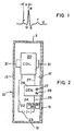
- Figure 1 illustrates a typical PQRSTU curve or trace made by a cathode ray tube or strip chart recording using an electrocardiogram device.
- Various characteristic parts of the curve are assigned the letters PQRSTU as illustrated.
- Each of the letters PQRSTU identifies either the top or the bottom of a transition point in the curve. If connections to electrodes are reversed the curve can be upside down from the way in which it is shown in Figure 1 and still be a useful curve.
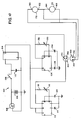
- Figure 2 illustrates a device embodying this invention.
- the device of Figure 2 includes a container 10 having a top wall 11. a bottom wall 12, one wall 13 to be form adjacent a user's chest and one wall 15 to be worn away from a user's chest.
- Wall 15 is clad with a layer of mu-mutal 15.
- the container 10 also has sidewalls, not numbered, to form a complete enclosure.
- a wire coil 20 surrounding a core 21 that is made of mu-metal or other material, that is quickly magnetized by the flow of electric current through coil 20 and has its magnetism quickly collapse when no current flows through coil 20.
- Lead 22 connects one end of coil 20 to battery 23 which has its other pole connected to precision voltage regulator 24 and then through lead 25 to a dual function square wave generator 26 that causes current to flow through the circuit completed by lead 27 to coil 20 at intervals which are adjustable from about 7.20 to 7.75 Hertz for the lower frequency and from about 72 to 77.5 Hertz for higher frequency.
- An adjustment means such a potentiometers 28 amd 29 is accessible through a wall of container 10 and connects to means within timing switch 26 to adjust the frequency of the cycle of the expanding and collapsing magnetic field.
- the same coil and core may be used to generate both fields or separate coils and cores may be used.
- the various elements of the device are firmly connected together and to the interior of container 10 by means not shown but known to the art.
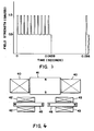
- Figure 3 is one plot of slightly more than one complete cycle of magnetic field strength against time developed by the device of Figure 2.
- the high frequency waves have a duty cycle of about 25% and the low frequency waves have a duty cycle of about 50%.
- High frequency waves are created only in the active portion of the duty cycle of the low frequency waves. Thus, while high frequency waves are present they have a duty cycle of 25%.
- the field strength of the high frequency waves is substantially equal to that of the low frequency waves.
- the effect of the high frequency waves is to change the character of the wave form of the low frequency waves.
- Figure 4 represents another very effective embodiment of the invention.
- the device of Figure 4 develops array patterned magnetic impulses that can be directed toward both the heart and the hypothalmus while directing a corresponding weak field in other directions.
- the device of Figure 4 includes a flat coil 40 surrounding a mu-metal core 1.
- Flat coils of this type are known to the art as pancake coils.
- pancake coil 40 Positioned below pancake coil 40 are cylindrical coils 42 and 43. Within coils 42 and 43 are mu-metal cores 45 and 46.
- the magnetic flex emanating from the device is a resultant that forms a flux pattern that concentrates flux in certain regions surrounding the device.
- the concentrated flux patterns will be directed toward the heart and hypothalamus and the effect of the magnetic flux will be magnified.
- the leads to the various coils are conventional and not illustrated.
- the coils are connected in series but they may be connected in parallel or independently wired as along as the timing of current flow will produce the correct wave forms in the correct phase with each other.
- the pain control circuit 100 is shown in Fig. 10.
- a battery such as a 7.2 volt 500 milliampere hour nickle cadmium battery
- a three terminal voltage regulator 104 such as a 7805 - 1 ampere 5 volt rated regulator.
- the positive end of the battery is connected to terminal 1 of the regulator.
- Terminal 3 of the regulator is connected to the negative terminal of the battery and also common return to ground.
- An optional phono jack 106 is connected to the battery 102 in the event a rechargeable battery is used.
- the circuit also contains and on-off switch 108. Connected in parallel with the voltage regulator also through terminals 3 and 1 is a 0.047 microfarad capacitor 110 which is needed to supress power surge spikes.
- the output terminal of the voltage regulator is terminal 2 from which +5 volts of electricity emanate.
- the power goes into a dual timer regulator chip such as a 7556 Intersil timer chip.
- the first timer chip 112 has terminals 1, 4, 14, 5, 2, 6, 7, and 3. Terminal 1 is not connected.
- Terminals 4 and 14 are connected in parallel and are the power supply leads into the first timer chip.
- Terminal 3 is connected to a .01 microfarad bypass capacitor 114 which is useful for suppressing spikes and avoiding latch-up.
- Terminal 7 is connected to common ground and back to the negative terminal of the battery.
- Terminals 2 and 6 are connected in parallel and are routed through a 500,000 ohm 10 turn potentiometer 116.
- Terminals 2 and 6 are also connected to ground through a 1 microfarad 35 volt DC capacitor 120.
- the combination of the 1 microfarad 35 volt DC capacitor 120 and the 500 ohm fixed resistor 118 and 500,000 ohm variable resistor (10 turn potentiometer) 116 determine the repetition rate of the output signal.
- the output signal comes through terminal 5 into the first end 142 of the output jack 140.
- the frequency output of this terminal is adjustable between 5 and 9 Hertz at a 50 percent duty cycle.
- Second timer chip 126 has terminals 13, 10, 9, 12, 8 and 11. Terminal 13 is not connected.
- Terminal 10 is connected to the power supply from the positive voltage emanating through the voltage regulator 104.
- Terminal 11 is connected to a 0.01 microfarad bypass capacitor 128 which is useful to suppress spikes and avoid latch-up.
- Terminals 12 and 8 are connected in parallel and are routed through a 100,000 ohm 10 turn potentiometer 130. Also included in the circuit is a 500 ohm one half watt fixed resistor 132 to avoid dead ending of the adjustment.
- Terminals 12 and 8 are also connected to ground through a 1 microfarad 35 volt DC capacitor 134. The combination of the 1 microfarad 35 volt DC capacitor 134 and the 500 ohm fixed resistor 132 and 100,000 ohm variable resistor (10 turn potentiometer) 130 determine the repetition rate of the output signal.
- the output signal comes through terminal 9 into the second end 144 of the output jack 140.
- the frequency output of this terminal is adjustable between 50 and 90 Hertz at a 50 percent duty cycle.
- the output jack 140 is connected to an input plug 150 which has two lead wires 152 and 154.
- the first lead wire 152 goes into one lead 160 of a coil 170 and into a second lead 168 on coil 172.
- these coils 170 and 172 can each be a 240 ohm resistance pancake type coil with a mu-metal core.
- the other lead 154 of the input plug 150 goes into second lead 162 of coil 160 and into first lead 164 of coil 172.
- the second lead 162 of the first coil 170 and the first lead 164 of the second coil 174 are connected together. Also, the two coils are connected in parallel.
- the two coils are energized with a current flow proportional to ohms law which holds that current is proportional to voltage divided by resistance.
- the two potentiometers are set by means of a frequency counter readout connection placed at the output jack 140 wherein the first timer chip frequency is approximately 7.35 Hertz and the second timer chip potentiometer is adjusted so that the second timer chip frequency is approximately 70 Hertz. Individual settings of frequencies of the timers are then fed into the input plug of the coil. When the coils are so connected, the coils will emit a magnetic field. This magnetic field is measured by a magnetic detector placed adjacent to one or both coils.
- each magnetic coil will produce about 5x10 ⁇ 4 tesla (5 Gauss) at each of the poles.
- the combined reistance of the coils must be about 120 ohms in order to produce the 5x10 ⁇ 4 tesla (5 Gauss) output and have the proper intermix wave shape.
- the placement of the coils are as follows.
- the north pole of one coil is placed slightly below the right knee and at the nerve exit point on the inside of the leg.
- the other coil is placed approximately at the T7 level, but with the south pole facing toward the patient's spine.
- This treatment configuraion is left on the patient for approximately 30 minutes after which period of time the coil at T7 is removed.
- the lower coil is left there for an additional 15 minutes and then removed.
- the above treatment treats the radial sciatica.
- the coil used on the leg is placed directly over L5 and the other coil is placed at T1. This treatment schedule is once again performed for 30 minutes, at which time the top coil is removed and the lower coil run for 15 minutes. This should eliminate both pains.
- the north or positive pole (which induces negative current) is used for treating extremities away from the brain and the other coil is used at the highest convenient point near the brain with the south or negative pole (which induces positive current) toward the spinal column at the level of about C3.
- transcutaneous electrodes When treating pain above the neck, transcutaneous electrodes must be substituted for the coils in order for the magnetic fields not to adversely affect the patient's brain.
- transcutaneous electrodes For treatment of dental pain, transcutaneous electrodes must be used and are attached as previously described. The electrodes are used in place of coils because we do not wish to influence the person's brain with these magnetic fields.
- the setting for the potentiometers are the same as previously described. It is possible to have multiple positive and multiple negative electrodes each in parallel.
- the treatment time if dental work is to be performed is 15 minutes to 20 minutes before dental work is begun and left on, if feasible, during the dental procedure. The electrodes should be left on for about 15 minutes after the dental work is done and then removed. If dental work is not to be performed, then the treatment time is approximately 1 hour.
- the lower frequency must be about 7.35 Hertz
- the upper frequency must be about 70 Hertz
- the intermix frequencies must be above 23 Hertz. If the intermix frequency cannot be achieved above 23 Hertz with these settings, the lower frequency may be set between 7 and 8 Hertz and the upper frequency must not fall below 70 Hertz nor above 77 Hertz in order to achieve an intermix frequency in excess of 23 Hertz.
- the minimum magnetic output at the poles of the coils should be at least 5x10 ⁇ 4 tesla (5 gauss) although magnetic outputs of 2x10 ⁇ 4 tesla (2 gauss) will produce desirable results if the treatment period is extended.
- the duty cycle of the circuit must be 50 percent in order operate properly.
- the circuit must produce a range of frequencies between 7 and 8 Hertz and must have a duty cycle between 40 and 60 percent.
- the minimum output at the poles should be at least 0.5x10 ⁇ 4 tesla (0.5 Gauss.)
- the wave shape is dependent upon the coil configuration and DC resistance. Therefore, any coil which produces the wave form displayed in the PQRST form as shown in Figure 1 is suitable for pacing the human heart. This is because the collapsing and expanding fields from the coil approximates the QRS shape of the heart as shown on an ECG. This is achieved through the parameters set forth above.
- the above described circuits produce a magnetic field wave shape of this form when the field is measured as above described.
- the pain control process of the present invention can be more broadly described as a process for reducing or extinguishing pain in a human comprising subjecting an area of the body surrounding the focus of the pain to two cyclic expanding and collapsing magnetic fields; the first cyclic expanding and collapsing magnetic field comprising an uncritically damped square wave form to produce a Fourier series of harmonics, having a fundamental frequency between 7.15 Hertz and 7.78 Hertz, having a duty cycle of from about 15% to about 65% and a field strength of at least 5.0x10 ⁇ 4 tesla (5.0 gauss); the second cyclic expanding and collapsing magnetic field comprising an uncritically damped ringing square wave form, having a frequency about ten times the frequency of the first magnetic field to also produce a Fourier series of harmonics, having a field strength of at least 5.0x10 ⁇ 4 tesla (5.0 gauss), and having a duty cycle of from 15% to
- the present invention further involves a device for reducing or extinguishing pain in a human comprising a first conducting wire coil, a core positioned in said coil, first means to produce a flow of electric current through said coil, said flow comprising an uncritically damped ringing square wave form to produce a series of Fourier harmonics having a fundamental frequency of from about 7.15 Hertz to about 7.78 Hertz and a duty cycle of from about 15% to about 65%, and said current flow being sufficient to induce a magnetic field having a strength of at least 5.0x10 ⁇ 4 tesla (5.0 gauss) in said core; and a second conducting wire coil, a core positioned in said second conducting wire coil, second means to produce a flow of electric current through said coil, said flow comprising a critically undamped ringing square wave form to produce a series of Fourier harmonics having a fundamental frequency of from about 72.5 Hertz to about 77.8 Hertz and a duty cycle
- the cores can be made of mu-metal or comparable material or else can be air cores. It is usually advisable to shield one of the poles of each core.
- the coils can be oabcake coils. Alternatively, each of the coils can terminate in an electrode.
- the present invention is a device for reducing or extinguishing pain in a human comprising a first conducting pair of electrodes to form a complete path, first means to produce a flow of electric current through said pair of electrodes, said flow comprising an uncritically damped ringing square wave form to produce a series of Fourier harmonics having a fundamental frequency of from about 7.15 Hertz to about 7.78 Hertz and a duty cycle of from about 15% to about 65%, said current flow being sufficient to induce a voltage of from 5 to 24 volts and a current between 45 to 500 microamperes of current; a second conducting pair of electrodes to form a complete path, second means to produce a flow of electric current through said coil, said flow comprising an uncritically damped ringing square wave form to produce a series of Fourier harmonics having a fundamental frequency of from about 71.5 Hertz to about
Abstract
Description
- This invention relates to an electronic apparatus which is capable of generating a magnetic field that is precisely tuned in order to interact with the brain and the heart in order to interact with the nervous system in order to counteract pain.
-
- No prior art devices to counteract pains through appropriate magnetic signals are presently known in the prior art.
- The inventors have discovered that the beginning of the normal cardiac cycle and response to pain cycle originates in the mid brain and the hypothalamus with excitation of the Purkinje cells and is oscillatorily propagated to the heart of source of pain, respectively. In dealing with the heart, the SA node in the heart is the site of the electric excitation impulse which directly produces the contraction of the cardiac musculature. The electric excitation is propagated within the heart by specialized conductive tissues which include in addition to the sinoauricular node, the AV node, the bundle of His with right and left branches, the Purkinje cells and fibers.
- The problem underlying the invention is that heretofore there has been no effective non-invasive instrumentation which can reduce pain in human beings. The present invention solves this problem by generating and applying pulsed magnetic energy to the pained area of the body, and it is effective to reduce such pain by employing particular waveforms and electro-magnetic values. More specifically, the production of two 5x10⁻⁴ Tesla (5.0 gauss) magnetic fields in the coil or coils, as a result of the intermixing of two pulsed frequencies, one between 7-8 Hz and one between 70-80 Hz, thereby creating a beat frequency, results in a heretofore unknown non-invasive technique for reducing pain as evidenced by a report supported by and approved by the FDA on a limited number of patients.
- In accordance with the invention, there is provided a device for applying a varying magnetic field to a human, comprising a first conducting wire coil (40), a core means (41,45,46) positioned in said coil (40), and first means (330) to produce a flow of electric current through said coil (40), characterized in that said device is adapted for reducing or extinguishing pain in a human; said flow comprises an uncritically damped ringing square waveform to produce a series of Fourier harmonics having a fundamental frequency of from about 7 Hertz to about 8 Hertz and a duty cycle of from about 15% to about 65%, said current flow being sufficient to induce a magnetic field having a strength of about 5x10⁻⁴ Tesla (5.0 gauss) in said core (41); and said device includes a second conducting wire coil (42,43), second means (360) to produce a flow of electric current through said second coil (42,43), said flow comprising an uncritically damped ringing square waveform to produce a series of Fourier harmonics having a fundamental frequency of about ten times that of the electric current flow in said first conducting wire coil (40) and a duty cycle of from about 15% to about 50%, said current flow being sufficient to induce a magnetic field having a strength of at least 5x10⁻⁴ Tesla (5.0 gauss) in said core; said first conducting wire coil (40) and said second conducting wire coil (42,43) are set so that both coils operate simultaneously with 50% duty cycles; and the first and second conducting wire coils (40,42,43) are tuned to each other so that the resultant mix of Fourier harmonics produces a beat frequency dynamic interaction of the two generated frequencies; whereby when said device is focused on an area of a human body relating to a locus of pain, said beat frequency produces an electro-anesthesia and causes normalization of the natural nerve pathway impulses to thereby reduce the pain.
- The device of this invention includes means to produce an expanding and collapsing magnetic field the shape of which, when plotted against time, is in the form of a square wave. For an adult human the frequency is from about 7.15 to about 7.78 Hertz. The magnetic field produced by the device has a minimum strength at its poles of about 0.5x10⁻⁴ Tesla (0.5 gauss). The square wave magnetic field must have a duty cycle of between 15% and 65%. The maximum strength of the magnetic field is limited only to avoid affecting others in the vicinity of the person wearing the device; it is not limited to any maximum value functionally. Affecting others can also be avoided by providing magnetic shielding or patterning the field with two or more coils so that the fields are directed toward the heart. Such shielding is available in the form of Mumetal, a trademark alloy having high magnetic permeability and low hysteresis and comprising iron, nickel, copper, chromium and manganese.
- The term "square wave" is used herein as it is understood in the art, namely, a wave that is essentially in the form of an abrupt rise in value from a zero level followed by a period maintained at some maximum value followed by an abrupt decrease in value to the zero level. When plotting value against time, variations in the value produces a wave form made essentially of vertical and horizontal lines. Departures from absolutely verical and horizontal lines through all portions of the wave are acceptable as long as the wave form of the magnetic field has an essentially square or rectangular form as understood by those skilled in the art.
- In the embodiment of the present invention designed to treat pain, the magnetic field impulses generated by the device will be at two frequencies differing from each other by a factor of about ten. The frequencies are mixed to counteract pain.For an adult, a pacemaking frequency of about 76 Hertz is superimposed on a square wave field having a frequency of about 7.6 Hertz. The higher frequency impulses are only used during the duty portion of the lower frequency impulses. .In addition, the higher frequency impulses have been found to cause a malfunctioning heart to stabilize to a normal heart rate more rapidly than if the lower frequency impulses are used alone.
- Referring to the drawings for the purpose of illustration and not limitation, there is illustrated:
- FIGURE 1 is a typical PQRSTU wave produced by a normal human heart.
- FIGURE 2 is a schematic illustration partly in cross section of a device embodying this invention.
- FIGURE 3 is a plot of magnetic field strength vs. time illustrating the preferred wave form of this invention.
- FIGURE 4 is a schematic cross section view of another device embodying this invention.
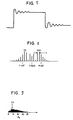
- FIGURE 5 is a wave diagram of square wave pulse showing ringing.
- FIGURE 6 is a wave diagram of a 7.34 Hertz square wave into a 100 kilohm input impedance on a 10 millisecond scale, shown in the PQRST type form.
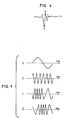
- FIGURE 7 a through d is a representation of a modulating sine wave, a carrier wave, a frequency modulated wave and a phase modulated wave.
- FIGURE 8 represents a typical spectrum of an FM signal, where F is the carrier frequency and f is the modulating frequency. The example is given for the cardiac system.
- FIGURE 9 is representation of a human heart ECG in the frequency domain showing a bandwidth of 30.4 Hertz with the dominant power at 7.6 Hertz.
- FIGURE 10 is a circuit diagram of the embodiment of the present invention used to counteract pain.
- This invention incorporates the discovery of new principles involving both linear and non-linear properties of biologic material and inorganic semiconductor systems. By generating certain energies at a distance from as well as in the proximity of these materials or systems and at the same time optionally detecting their changes and emissions, unique new characteristics can be elicited and observed. Biologic as well as inorganic systems, when excited by external energies of specific, mixed or varying in a narrow range of frequencies, polarizations, wave forms and intensities, will have their own characteristics changed and in turn will change the characteristic of the energies impinging upon the system. Thus a characteristic transmitted energy impinging upon or traveling through a given self resonant system will stimuate the system to respond with a transmission of its own which is different from its transmission characteristic when undisturbed by the impinging energy. These two separate characteristic energies will interact synergistically producing not only greater effects at the disturbed local material sites but also will produce non local effects at other sites. The interaction of emitted energies from artificial sources and biologic systems, if both are characteristically self resonant at some compatible fundamental or harmonic frequency results in the formation of an informational channel between the source and system. The informational channel in turn has a characteristic resonance compatible with the source and system. The channel frequency is able to modulate the interacting systems with diode-like forward-reverse voltage fluxuation. The channel is therefore a system frequency modulator.
- Transverse and longitudinal wave and impulse energy interactions with in vivo and/or in vitro biologic material require precise tuning, magnitudes, wave shapes, mixtures, polarizations and durations in order to produce significant effects.
- Living biologic systems exist and function through a series of physical-chemical-electro magnetic interactions. The physical and chemical interactions are fairly well understood by traditional science but a significant number of potentially beneficial advances in the medical arts have been ignored or considered of minor importance because of a lack of understanding of the non-linear interactions that take place between biologic material and electromagnetic energies. The areas of medical research which have been concerned with the electric or magnetic properties of living systems for the most part are based on the Hogkin-Huxley model of the Giant Squid Axon and the sodium-potassium pump. This model predicts that biologic material must interact with electric and magnetic energies in a linear manner, even though much research exists demonstrating non-linear effects do take place in biologic material as a result of electromagnetic interactions. The cardiovascular system is a notable example of a system that in some respects is highly linear, and in others behaves highly non-linearly.
- The present invention is based on research and experimental evidence which indicates that at least three major components of a living system operate primarily on very non-linear far from equilibrium principles while yet retaining and utilizing their inherent linear qualities. The three components are the brain, the cardiovascular , and the nervous systems. This invention is based on research and test of devices which meet the criteria of a mathematical model which applies to a multi-system interaction and hence involves the description applicable to very non-linear systems. For example, we consider in detail here the neuronal FM information channel and the communications between the AM muscle-mechanical component for the cardiocascular system. The information channel interactions of a multi-system such as the cardiovascular system operate in an extremely non-linear self organizing manner. We can treat biological processes as linear only if we consider a small region of activity such as single, neuron firings within a small cross section of a limited area of the tissues. These limited regions of functional activities are able to be successfully described by the Hodgkin-Huxley, sodium-potassium pump model.
- The inventors have developed and tested the herein described devices according to our mathematical model and these results and our model match very well. In order to clarify some of the physical-electrical concepts involved with our invention, some of the key issues are described. It is well known that certain materials such as quarts, rochelle salt, and barium titantate exhibits piezoelectric qualities. That is if a mechanical stress such as a sharp impact or impulse is applied to a piezoelectric material such as quartz, a substantial electric potential impulse develops across two of the crystal faces of the material as a result of distortion of the lattice structure of the material. Conversely, if a fluctuating electric charge is placed across the two active crystal faces the piezoelectric material will mechanically oscillate at its characteristic vibratory rate which is determined by the size and cut of the crystal. The mechanical-electrical reciprocity makes this type of material useful as a timing device.
- It is less well known that bone and collagenous material in biologic systems are not only piezoelectric but may, under the proper electrical-mechanical conditions function as semiconductors and also as light-emitting diodes. The apatite crystal substance of bone is P type semi-conductor material, and the collagen fiber is N type semi-conductor material. The areas where these two co-exist is a PN junction diode which if forward biased with a voltage or induced current can emit an electromagnetic energy usually in the infrared region of the optical spectrum. With this information in mind, envison precisely formed magnetic impulses with shapes of varying phases and wave front envelopes emitted from an artificial source at precisely timed intervals penetrating and interacting with biologic material that has among other properties, piezoelectric qualities.
- As is well known, magnetic fields will induce currents in conductors, and if we consider the field effects of the above described magnetic impulses on the capacitive, inductive, and resistive as well as the piezoelectric and semi-conductor properties of biologic material, it will immediately become apparent that the artificially emitted field will not only induce a reciprocity of field emission from the biologic material it is acting upon, but will also intermix with the re-emitted signal. The interaction of the emission-remission apparently behaves as an informational channel. The informational channel appears to be a frequency or phase shift modulated magnetically coupled system.
- The information channel band widths are narrow with high "Q"s. The informational channel of the human cardiovascular system apparently has a band width of approximately 30.4 Hertz with a frequency swing of plus or minus 15.2 Hertz. and the second Bessel null at about 7.6 Hertz. The human nervous system apparently has an informational band width of about 304 Hertz with a frequency swing of plus or
minus 152 Hertz and the first Bessel component around 23 Hertz which represents the mix of the 7.6 and 76 Hertz generated signals. The human brain informational channel band width is approximately 3040 Hertz with a frequency swing of plus or minus 1520 Hertz, and a more complex mix of frequencies peaking between 70 and 123 Hertz. - It can be seen from the above that the informational channel of the human brain nervous system is about 10 times the band width of the informational channel of the cardiovascular system. The human brain informational channel band width in turn appears to be some 10 times the informational channel band width of the human nervous system.
- It is a well known engineering fact that in order for signals of given frequencies to be faithfully detected and reproduced that the receiving channel must have a band width at least 10 times the frequency of the highest emitted frequency which must be processed. Informational channels of biologic systems seem to need just the optimum band widths for high "Q"s at specific resonant frequencies and at the same time possess the inherent capability to be as free as possible from outside interference or "static". Narrow band FM is therefore the logical choice which nature evidently selected.
- Although many higher frequencies than described herein can be utilized to produce various significant biological effects the present invention relates to non-invasive devices which emit magnetic pulses that can penetrate through and interact with biologic materials and potentially all systems of the body in what is known as the ELF/VLF frequency range. These devices operate at low intensities and except for the noted exceptions, without direct contact with the material affected. Through this effect, the present invention can enhance the ability of biologic systems toward a state of improved function in many areas of organic dysfunction.
- The present invention is concentrated on improving effects upon cardiac tissues, excitable tissues, and neurological systems. Each organ of the body has a given electrical or electromagmetic characteristic with which a given wave form will resonate and affect the function of that organ. The key principles involved are as follows: magnetic fields generated at specific frequencies, and the harmonics of those frequencies, wave shapes, polarizations, or electric currents from cutaneously attached electrodes, will penetrate the system and stimulate specific and general nerves, and other parts of a biologic system either electrically, piezoelectrically, paramagnetically or chemically, or all in concert when certain biologic material resonant conditions are met. There are also variable and mixed frequency ranges and intensities of magnetic impulses and electric current impulses which can affect specific and general areas of biologic tissues.
- This invention utilizes the theoretical constructs that involve the description of a nonlinear, non-equilibrium information system that is a coherent, resonant locked and a system of an infinite series of Bessel functions from an FM constant energy signal process.
- Neuronal processes in the CNS, heart and brain are theoretically describable as a coherent "self focusing" informational channel which is composed of a series of harmonics represented as Bessel functions which are locked together at proper resonance when healthy pathways occur. The piezoelectric properties of bone and collagen as well as the neuronal pathways operate in concert to produce normal informational signals.
- The inventors can definitively formulate nonlinear, dispersive properties in terms of pulse type eigenfunctions or soliton solutions. Soliton waves are said to be orthogonal in the sense that two or more crossing each other's path, essentially do not interact and hence do not distort or disperse. The phase velocity is obtained proportional to the square of the amplitude of such a system. The key to the soliton type phenomena is that soliton configurations arise so that the nonolinear form balances the dispersive type mode in a "meta stable" or critically stable mode.
- Certain parts of the biological-electrical system can be treated as a semi-conducting electrical system. Certain coherent collective electromagnetic phenomena are describable by a set of non-linear equations yielding solutions of energy propagation in which dispersion is balanced by re-coherence yielding solitary wave solutions. Such a model of neuronal/electrical activity can describe longitudinal neuronal information transmission which is characterized by the self-organizing properties described by Prigogine thermodynamics.
- We apply this thermodynamical picture to describe systems that when a diode or diode array is properly connected to elements such as an antenna and a capacitor and the system placed so as to be exposed to random broad band noise, the noise can be rectified and stored in the capacitor as a unidirectional energy reserve. This comprises an example of a self-organizing system. Biological systems as well as this device employ these principles. For example, the actual electrically stimulated collective, coherent, solitary wave modes which proceed from a semiconductor substrate and diode-like array which are represented by the Purkinje cells and corpuscles as well as other neuronal cells, act in concert with nerve, bone and blood systems.
- Low frequency radiations affect biological material and act as a systems narrow band FM informational system which utilizes almost constant energy input but contains very large informational channel capacity. These sytems are examples of systems describable by the Prigogine far from equilibrium thermodynamics. The system described herein is an open, far from equilibrium one, which operates with a continuous energy flux. The energy flux in this case is both electro-magneto-dynamic as well as hydrodynamic and in its normal mode of operation is a systems which loses very little energy. These systems are nonlinear and self organizing in that a small flux field perturbation can produce a large change of the system's state properties. The inventors have demonstrated that the fourier bessel equation which described the FM system describes an informational channel which is frequency modulated within the lossless channel of the soliton wave solutions to a set of magneto-electro-hydrodynamic equations. The waves going into and out of the heart must impedance match each other so that the system is relatively lossless between the present invention and the physical person.
- In the conventional theory the wavelength of an electromagnetic signal of around 7.6 Hertz is inordinately large and hence would be seen as a wave so slowly changing in time as to not interact significantly with matter. Therefore, in general, electric field effects are minimal in the ELF (extremely low frequency - from less than 1 Hertz to 300 Hertz) region. On the other hand, magnetic impulses at ELF frequencies act as perturbations in the earth's steady state magnetic field and are "seen" by matter as impulse perturbations of this field. With the exceptions of portions of the visual, tactile and auditory systems, living organisms primarily utilize and generate frequencies in the ELF region. The intensities of these radiations are however significantly below threshhold for thermal effects upon or in biological tissue. The reason such low intensities of pulsatile magnetic fields generated by external sources produce such dramatic effects on biological tissue and their processes occurs because they can be made to match the internal processing mechanisms of the biological tissue. This matching of externally generated imposed fields to those utilized by the biological systems occur when proper impedance matching conditions exist.
- In accord with the inventor's model, high intensity external signals may not impedance match well enough to produce phase shifting or soliton dispersion but may produce thermal agitation or noise and at extreme intensities, molecular bonds can be broken. The inventors can choose specific low frequency pulsed electric or magnetic signals which will induce magnetic pulsations that recohere and reinforce normal, biologic system functioning when these field forms are such as to be able to produce the normal signal modes in the desired tissue areas. In their clinical experience, the inventors have found a remarkably narrow range of frequencies in different individuals and in the same individual at different times in regard to the apparent characteristic pulsed emissions of given organ systems. That is the given pulsed wave signals which induce a given desired healthy biological function response on one person seems to be able to elicit the same response in other people. The inventor's formalism describes a structure of both the externally generated fields and the internally generated biological fields. The longitudnal (phonon) like modes composed of the Fourier Bessel series fine structured components comprise the soliton model.
- The soliton model of biological signaling becomes useful in describing the various conditions of bioelectro-magnetic processing. Tissue nonlinearities determine the dispersion and/or coherence of the various signal system in the biological system or human body. Disruption or enhancement occurs because external signals transduced by the nonlinearities of the tissues form into Soliton like waves. These waves, then can modify and recohere processes which are too dispersive and hence reinforce normal neuronal or other signal paths. On the other hand these waves, at other frequencies, wave forms and intensities can increase dispersion and hence introduce disruption and biological damage in the system. The reason that pure magnetic impulses are useful in the application of modifying biologic tissue is because frequencies in the ELF range have their electric and or electromagnetic component modified by the bioligical tissue during the signal's excursion through the tissue so that it becomes a pure magnetic signal. Essentially, in the soliton model, tissue acts as a transducer device and longitudnal wave rectifier so that they transform waves which carry horizontal components into longitudinal wave components. Losses occur when impedance mismatching exists and other kinds of losses may also occur such as eddy current and hysteresis losses. Biological tissue is "transparent" to some ELF frequencies, therefore, frequency wave form and pulse repitation rate specificity is extremely critical to producing an effect within or on the biologic system under consideration. The effect of pulsed magnetic fields that interact with biologic material is extremely similar across a species. In the case of humans, the system's own informational channels react to the proper pulse fields as its own pulse field. Therefore, the reason biological matter can utilize square wave forms more efficiently is because of the ringing that occurs in these wave forms which produce a unique set of Fourier components. These components supply the complexity of structure of its electromagnetic field necessary to carry the needed bit rate in a biologic informal channel. Thus theoretically, the special ringing of biologic material is produced primarily by the piezoelectric qualities of bone and collageneous matter. Figure 5 is a drawing of a square wave pulse showing the damped sinusoid ringing trails. When a pulse with a square wave form passes into biologic material which contains piezoelectric qualities, the square wave form induces a complex secondary delayed pulse in this material. The external square wave pulse and the induced complex delayed pulse together produce a wave form which appears very similar to the QRS complex wave. Figure 6 shows the output of a 7.3 Hertz square wave modified by piezoelectric biological material and it can be seen that the form resembles the PQRST complex.
- These sytems involve dynamic coherence and dissipation which gives their structure and energy constitution; all soliton phenomena is "dissipative". Processes can involve either static or dynamic stability and/or equilibrium. Non equilibrium states are maintained to create the conditions for no dissipative "loss less" conditions so that information is not disturbed or disrupted. The high bit rate is maintained because the FM process creates and utilizes an infinite number of locked resonant harmonics in the asymptoid limit. One needs to consider the Bessel equation rather than the Fourier equation since in the application to the human body, the inventors are considering that most organs and systems are best defined as spherical radiators. The skull and the heart can act as a spherical receiver/transmitter antenna. For example the Fourier equation can be applied to moving waves in a plane whether mechanical, acoustic, or electromagnetic, whereas the Bessel equation can be applied to processes which have approximately spherical symmetry and hence is more applicable to wave phenomena in organs. In some cases, as in local biological functioning, a plane or approximately flat surface excitation can be considered. Essentially, the Fourier equation represents a simpler form than the Bessel equation. One will find that in certain applications the Fourier equation will suffice for a formalism but in general the inventors will be dealing with the Bessel equation and its solutions. These solutions are of a specific form which are termed Bessel functions. In some cases we can express Bessel functions in terms of gamma functions. In the case of the Fourier equation the solutions are usually in terms of trigonometric functions such as sines, cosines, and in some cases hyperbolic functions.
- It appears that the electrical and electromagnetic and magnetic human body functioning involves a complexity of wave function solutions that in general are not describable in terms of simple trigonometric functions but involve relatively complex series of waves. In fact no simple sine wave or other simple wave form will effectively interact with biologic tissue to produce either a functional enhancement or diminution.The inventors have utilzed a damped square wave in which ringing and wave distortion by the local impedance of the material considered can be expressed as a complex series of trigonometric functions. Essentially, the Bessel formalism can be utilized to describe the wave envelope and amplitude modulated components with the envelope in which dispersive losses due to damping occur. Insulator blockage due to a material of high dielectric constant would produce such observable generated fields where frequency and wave forms were not optimum.
- In a normally functioning biologic process a steady electric and magnetic process proceeds which is modified by sensorial, and motor glandular modification for different activities. In general, the electric, magnetic and electromagnetic processes operate in such a manner as to produce a steady state condition. This is acomplished when the damping or dispersive losses are balanced by recoherence produced by the nonlinearities of the system.
- Biological systems and proceeses are highly nonlinear. This allows them to utilize highly complex and dispersive wave forms which have many Fourier/Bessel components. The only manner in which processes can function in a coherent and continuous manner is to be structured nonlinearly in their processing of energy much as electrical energy so that dispersive losses are overcome or recohered.
- A demonstration has been achieved that the Korteweg-de Vries equation and the Bessels and Fourier equation are derived from a fundamental wave equation. The Korteweg-de Vries equation defines extremely well, the manner in which a non-linear term defines the "balances" or recoherence of a dispersive term. The solution to this equation is well defined and are termed solitary waves or solitons. Although the original application for the Korteweg-de Vries equation was to hydro-dynamics systems, and many other systems involving wave phenomena, the inventors have demonstrated that they can formulate an analogous equation with equal success to electro-magnetic and magneto-dynamic phenomenon.
- In fact, the biological "signal" and "communication process" involves electrical, magnetic, and electromagnetic energy which utilizes the complexity of the Fourier-Bessel wave components and the coherent resonances of the soliton wave form. Essentially, we can picture the biological system as a communication network which utilizes square wave like impulses (analogous in a sense to an on/off mode) to activate, diminish and utilize electro-chemical, biochemical and energy potential processes to produce and regulate a variety of biologic functions. These functions are performed in specific organs, cells, nervous tissue, etc. The form slope, size, structure and composition of such systems determine the manner in which information is processed, cohered, dispersed, etc. by their nonlinear mechanical, biological or electrochemical energy forms.
- The wave equation for a series of single closely approximate sine wave impulses is given by the equation:

where co is the velocoity of the wave and the amplitude,. U, is a function of space and time. The general solution to this equation is of the form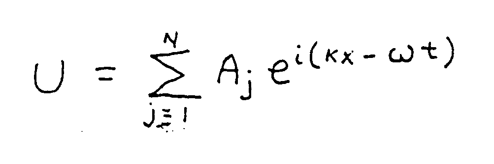
for a series of amplitude constants, Aj . The dispersion relation for the systems described by this wave equation are k = ν/co where k is the wave number given in terms of the wave length of k = 1/λ and ν is the frequency. - In proceeding to demonstrate the relationship of this wave equation to more complex wave equations which describe impulse waves, square waves, coherent soliton waves, etc., one will have different dispersion relations. Systems which exhibit dispersion (such as in the Korteweg-de Vries equation or other Soliton equation),


In order to examine the fundamental relation of the Korteweg-de Vries equation and the Fourier-Bessel equation, we utilize a general dispersion relation. The inventors derived the Korteweg-de Vries classical soliton equation to the classical wave equation and have also derived the Fourier-Bessel equation from the classical equation. The inventors demonstrated the manner in which these equations are related to each other in a fundamental manner. These equations allow the inventors to describe the manner in which a complex electromagnetic signal can remain coherert in space and time as a soliton or instanton wave. The inventors solve both the classical and semi-classical equations which are applicable to the biological system. The key is that the Fourier equation applies to rectilinear plane membrane surfaces and is useful when the inventors consider an approximately small area of tissue and can approximate this surface as a flat plane. More applicable to the inventor's biological case is the Bessel equation which applies to circular or curvilinear membrane surfaces or radius or curvature ax and ay . Hence we proceed from polar coordinates (r,ϑ,φ,t). Let us now define a dependent functional variable as z(r,ϑ,φ,t). Then we have
Let us consider the case where the symmetry of z will make z independent of ϑ and we have the boundary conditions on z as z(a,t) ≡ 0; z(r ,ϑ )= f(r); and
We term f(r) the deformation function. Let z = T(t)R(r) where R(r) becomes the spatial variation function. We have:
which yields

and letting B=0 for our second initial condition we determine R by setting u =µr which yields the form
This is Bessel's equation and we have the first solutuion for this form as

Since the Bessel equation is a second order equation, there is another solution which has a singularity at the origin and hence we rule it out. The boundary conditions require that J₀ (µa) = 0 and
where αn is a root of the Bessel function J₀ . We also have
We can examine the system in terms of FM (frequency modulation). In an FM system, no change in output power amplitude occurs and frequency is modulated and detected as a voltage. Fourier-Bessel functions encode amplitude in addition to the frequency encoding. Frequency is displayed into the time domain and can be converted into the frequency domain. Both modes are then able to be detected and analyzed. As body electrical functions communicate by neuronal functioning, a full Fourier spectrum is representative of amplitude. Therefore the biologic neuronal system can guarantee an FM signal containing a rich array of Fourier-Bessel components which transmit the necessary signal array to be detected and analyzed by other neuronal systems. Hence, we have a method to analyze CNS and organ signals which are information transmitters and receivers. - If maximum deviation and frequency variations are suppressed, inhibited, or magnified, then body function should be modified toward a diseased state. Fourier components should be seen as missing when ECG or neuronal activity is measured. The present invention is utilized to re-establish missing components and cancel unwanted components which may represent a "shorted" circuit creating chronic pain. A system with chronic pain may also be able to transmit useable and necessary components.
- Thus when a set of neuronal and other impulses do not exist, i.e. amplitudes and frequency are not present as represented by their fourier components, then non-optimum information transmission results and we may term this condition a diseased or injury condition. Receptor filter detectors and analyzers of the body cannot read these signals in such a manner as to function normally and efficiently.
- The soliton model of biological signalling becomes useful in describing the various conditions of bioelectric-magnetic processing. Tissue nonlinearities determine the dispersion and/or coherence of the various signal system in the biological system or human body. Disruption or enhancement occurs because the external signal transduced by the nonlinearitiers of the tissue form into soliton like waves. These waves, then can modify and recohere processes which are too dispersive and hence reinforce normal neuronal or other signal paths. On the other hand these waves, at other frequencies, wave forms and intensities can incerease dispersion and hence introduce disruption and biological damage in the system.
- The information transmission capacity is proportional to the band width which is "chosen" to match the needed Fourier components. FM systems require very little power expenditures in relaying information as frequency modulations. FM systems also are highly resistant to static or external energies of large magnitude which would normally interfere with a frequency modulated system and is therefore optimum for biologic information transfer systems that respond to amplitude modulations.
Frequency modulation is a constant power process and the power of the modulated wave does not change as the degree of modulation changes. The frequeny-domain representation of an FM wave consists of a carrier and sidebands spaced in frequency around the carrier. The spacing between frequency components is equal to the modulating frequency fn . Theoretically, the FM waves contain an infinite number of sidebands. The sideband energy, however, falls off very rapidly outside the peak frequency deviation where the deviation is measured with respect to the carrier frequency. The amplitudes of the various frequency components, including the carrier component, change as the deviation changes. This is a consequence of the requirement that the total power remain constant regardless of the deviation. - The relative amplitudes of the frequncy components are in the same relationship as the relative amplitudes of Bessel functions of the first kind. Bessel functions of the first kind are designated as J₀ or Jn for n = 1, 2,..... The complete characterization of the frequency component amplitudes is

where n is called the order and represents the frequency component number (p=0 for the carrier, n=1 for the first sideband, etc.) and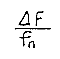
is called the argument and represents the modulation index. The modulation index, denoted as β , is defined as the ratio: peak frequency deviation divided by the modulating frequency f. - Bessel functions are the solution to Bessel's differential equation, just as the standard trigonometric functions, sine, cosine, etc., are the solution to differential equations.
- The information of interest in FM is: the carrier frequency (F), the modulating frequency (f), and the deviation (ΔF). The carrier frequency F is obtained by reading the spectrum-analyzer center-frequency dial and the modulating frequency f is obtained by calculating the frequency spacing between two adjacent components by use of the calibrated dispersion. The deviation (ΔF) can, however, not be determinable directly. First, one obtains the modulation index from which the deviation is then calculated.
- Transmission and reception of biologic signals require the proper band width about the carrier frequency to faithfully produce and detect the signal. To be a faithful transmitter or receiver the bandwidth needs to be at least ten times greater than the band of frequencies carrying the information to be transmitted or received. The power spectrum of Bessel nulls and Fourier components defines the sensitivity of the organism.
- In Figure 7 we represent various wave forms in the time domain. The top wave form represents an unmodulated sin x or cos x wave that can act as a modulator of a carrier wave, which is represented second from the top. The third wave form represents a frequency-modulated FM wave. We also represent a phase modulated PM wave. Full use of the Fourier power occurs at the second Bessel function for the cardiac system. We treat the informational channels of the biologic system in our model of this invention as describable in terms of frequency and phase modulations (FM/PM). The 1/t term is incorporated as the simultaneous but inverse function of the argument which is the modulation index. Biological informational channels therefore employ FM/PM as multi-tone FM with the muscle contraction AM "pilot" component at about 1.23 Hertz. This allows the downward stepwise frequency oscillation divisions at 7.6 Hertz to occur as sum and difference sideband frequencies.
- In Figure 8 we represent the frequency domain. In Figure 9 we represent a typical spectrum of an FM signal, where F is the carrier frequency and f is the modulating frequency. The example is given for the cardiac system.
- We deduce that the body information signal utilizes FM and relates to the piezoelectric effect of bone and muscle material. The hydroxyapatite-like piezoelectric impulses interacting with the CNS make up the FM informational signals which are the Bessel functions of the modulating frequencies. The mechanical oscillator transmitter in biologic systems would be vibrations and stresses in the bone and collagen resulting from motions within and without the system. These stresses and vibrations in turn generate electrical impulses and waves which radiate within and without the system. The biologic receiver system primarily operates as a feedback detection system with the CNS and, particularly that the Purkinje cells in the mid brain area serve as efferent diode-like detectors.
- We can write the Bessel function of zero order, denoted by J₀(x), and is given the power series

which is valid for all "k" and even can be valid when "k" is not an integer and k! is the factorial k. This is for the Bessel equation initial conditions of Y-1,
- We can also write the Bessel integral in a bounded region
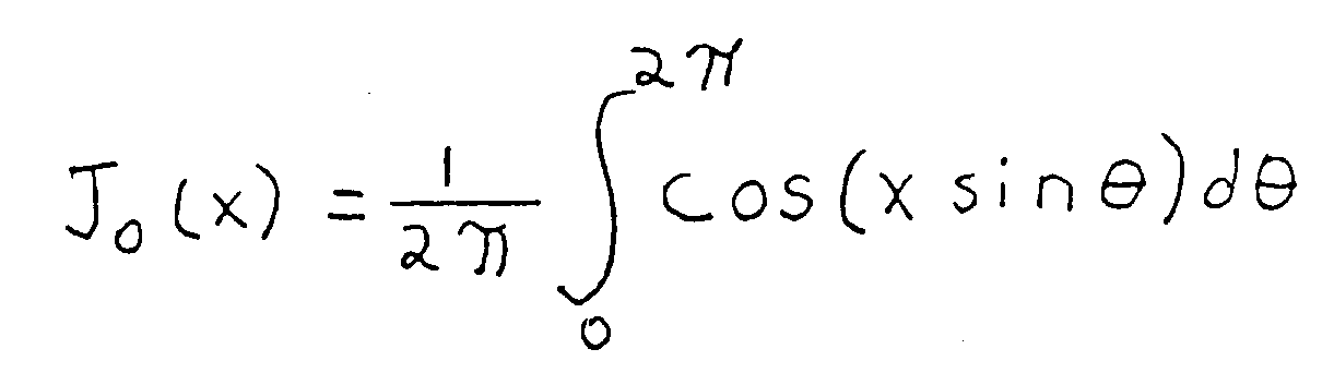
and for the asymptotic condition x→∞ we can write
where
represents "of the order of" for |arg x|< π. We see that there is a relation between the J(x)'s and the trigonometric functions. - In general we can write the expression for the p'th order of the Bessel function,

For the Bessel function of the first kind of zero order,
Also we can write p'th order Bessel function as
for |arg x|<π. This form uses Sommerfeld's integral representation and the method of steepest descent for a fixed "p" and asymptotic approximation for |x|→∞. We use "p' as a positive integer for our present consideration and hence do not need to generalize to the appropriate definition of p! for arbitrary "p". If we need to use the Bessel expansion for arbitrary "p", we can use the expression for p! in terms of the gamma function as
for p≧0 which we can solve and Bessel functions and the circular trigonometric functions are related. For large "x" then we can neglect the
term. That is, for the larger argument, the closer the Bessel function resembles a decaying circular function. We can also write the trigonometric functions in the terms of the Bessel function as

and

so that a sinusoidal function can be expanded in terms of a series of Bessel functions. Bessel functions are orthogonal. - We can write trigonometric functions in terms of exponentials. This kind of form is sometimes useful for epansion formulas. We can write cos x + i sin x = eix and use expansion formulas of the type

- We can write an expresson for the FM spectrum wave as

where "a" is the Bessel coefficient, F is the carrier frequency, "f" is the modulation frequency, A is the carrier amplitude, ΔF is the peak deviation, and ΔF/f is defined as the modulation index. We expand this expression in terms of a set of discrete sinusoids which appear at the carrier frequency, F, and sidebands or on either side of the carrier and are spaced at the modulation frequency, f, apart from each other. Theoretically there is no limit to the number of sidebands for an infinite frequency distribution. The amplitude of the carrier and the various sidebands are determined by the product of the original carrier amplitude, A, and the value of the appropriate Bessel function. The order of the Bessel function corresponds to the sideband number denoting the carrier component as number zero. The argument of the Bessel function is the modulation index ΔF/f. - The amplitude of the carrier component is modified for the FM process by the factor

the carrier component of the modulated wave is smaller than the amplitude of the unmodulated carrier. In some cases, the carrier component can go to zero, and this is called a null carrier and occurs when
The Bessel zeros are used to determine the frequency deviation. The reason the FM process is a constant energy process is because energy is removed from the carrier and supplied to its sidebands, so that the energy of an FM wave is constant regardless of the degree of modulation. This is in contrast to AM where the carrier amplitude is constant and the modulation process adds energy to the wave. The process of body metabolism could not supply the rapidly varying energy component to utilize AM information processes. It is a fact that FM is a constant energy process that makes it feasible for the body to utilize such a system for its informational carying capacity. - We can write an expansion for an infinite series of sinusoids with Bessel coefficients as
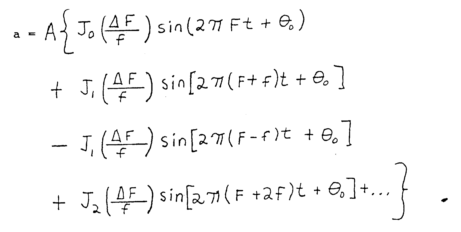
- We derived the values for the Bessel functions used in this patent from a plot of the first 8 orders of Bessel functions as shown in Figure 4-4a on page 85 of the text Spectrum Analyzer Theory and Applications - by Morris Engelson and Fred Telewski. A plot for each Jp(t)where "t" is an arbitrary index for the Bessel function and can be given as

- The neuronal pathways and their specific biologic material utilize a relatively narrow band FM spectrum. The FM spectrum sideband spacing can be determined, for example, in the case where the carrier component goes to zero. This is called a carrier null and happens when

The first carrier null occurs at a modulation index of 2.4, as can be seen in Figure 4 - 4a , where the zero crossing of J (t) occurs. - For our pain treatment invention, narrow band FM modulation leads to a series determined in detail by two coupled Fourier Bessel equations with a time varying coupling "constant". The carrier frequency, F, has been determined experimentally to be about 70 Hertz and Δ F = 150 Hertz. Experimentally, the modulating frequency, f, which results from a dual frequency beat frequency, is about 23 and therefore the approximate Bessel function argument is 2. The Bessel functions for n = 0,1,2,3,.... are J₀(2)∼ 0.2, J₁ (2) ∼ 0.58, J₂ (2) ∼ 0.36, and J₃ (2) ∼ 0.14, and the higher order Bessel functions are all approximately zero.
- Now we determine the FM spectrum for the cardiovascular system as follows: the carrier frequency f, or f = 15.2 Hertz, where the peak frequency of the Fourier spectrum of the ECG output is 7.60 Hertz for an average heart beat of 1.23 Hertz. The effective narrow band FM is ΔF = 30.4 then the Bessel function argument or index of modulation is t =

- From Figure 4 - 4a with argument t =

and all the additional components of Jn(2) for n ≧ 5 are zero. The largest Bessel function component for t = 2 accrues for J (2) or the second Bessel function for a Bessel function of the first kind. - Note that the carrier null or zero occurs for

=0, for an index of modulations of

- The inventors have demonstrated the derivation of the Fourier-Bessel equation from the classical wave equation and have been able to derive to Korteweg-de Vries equation from the classical wave equation and the generalized dispersion relation. The inventors have found the soliton type solutions and related these in a fundamental manner to the Bessel series harmonics which represent information and operate in a near "lossless" manner. This formalism describes an informationally stable system of equations in which predominate dispersive losses are recohered. The FM informational process occurs in such a manner in the human body so that solitary wave pulses are monitored in a normal healthy system. The inventors will now outline the mathematical formalism for such a system in term of solitary wave physics. They proceed from three different but related formulations.
- First, starting with Maxwell's equations and the continuity equation, second from the generalized dispersion relation, and third, from Laplace's equation or the classical wave equation. The inventors present this latter derivation and relate it to the second method, since they can demonstrate the most direct relationship between the solitary wave coherent process and the complexity of the Fourier-Bessel FM signal channel process. They consider either steady state or space-time variational conditions. Proceeding from the Maxwell equations and the continuity equation also lead to equations having soliton solutions. Solitons have solitary wave forms described coherent states which are collective such as phonon like acoustic modes and/or other longitudinal collective modes. The inventors proceed from Laplace's equation which has been related to the classical wave equation earlier in this document. The inventors demonstrate the relationship between the classical wave equation and the Korteweg-de Vries equation. It should be noted that the Laplace form has many general applications, such as to thermodynamic, electromagnetic. and gravitational phenomena.
- The three-dimensional Laplace equation is written as:

where U represents a general wave ampltude as a function of the independent variables x, y and z. - The two dimensional form is:

where U is now considered a function of x and y. The inventors can now define y²= -co²t² for y = icot which can represent a temporal component for wave velocity, co . Upon substitution, the above equation becomes
which is the one-spatial-dimensional and time-dependent classical wave equation which has solutions of the form U∼ei(Kx-ωt). The point we make here is that we can consider these equation forms to represent waves. - Now let us return to the wave equation we proceeded from before. We have wave function U(x,t) in three dimensions as U(x,y,z,t) as

for
for the simple case of ω² = co²k²and the temporal component is icot for co the velocity of wave propagation. Note that Laplace's equation is a subset of this equation where we have two components of space x,y and no temporal component. If we consider three spatial dimensions we can formulate the dispersion relation for k²= k


for the incident wave

for the transmitted wave. - The inventors use as a general dispersion relation

where

We will now proceed and consider one spatial dimension only. The first two terms are the usual classical wave equation, the group velocity,

Then we have the kinematic equation of the form

where higher order nonlinear terms are neglected so that we use β₂ and β₃ respectively to represent quadratic and cubic nonlinearities The presence of a quadratic nonlinearity for β₂ ≠ 0 and β₃ = 0 yields the one spatial dimension Korteweg-de Vries equation
where in simplest analytic dispersion relation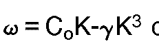
- In the nondispersive case, ω = cok, and for quadratic nonlinearity, where dispersive processes exist, these are self-focused by the recoherence of the wave due to the nonlinear processes in the system.
- The solution to the above equation is a sinusoidal pulse in a nonlinear medium characterized by amplitude-dependent phase velocity of the form

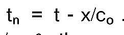

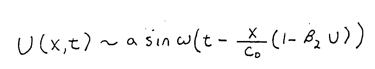
for
If we do not have a discontinuity then we have the lossless Korteweg-de Vries condition for a longitudinally stable stationary solution,
for β₂>0 and for velocity v>co if γ>0 and u<co if γ<0 .The above solution for the first case γ>0 is the conventional soliton solution. The velocity difference v - co is proportional to the amplitude of the soliton pulse. The product of the wave amplitude and wave width is proportional to |γ|/coβ₂ and the spatial width of the pulse is proportional to 3π|γ|/coβ₂ . The Korteweg-de Vries solutiuon represents a periodic nonlinear stationary solution which has an infinite number of harmonics locked in phase and velocity. These sinusoidal pulses lock together at resonance and form a synoidal wave form. - The fact that there is an infinite number of harmonics allows the informational capacity of the system to be extremely large for a small amount of constant energy input in the wave. The synoidal wave phenomena allow for extreme stability of the system when the infinite number of harmonics is locked into resonance moving at a reduced velocity, where v < co . Solitary waves or soliton-soliton interactions do not disrupt the synoidal process and hence neuronal processing utilizing a system like this in CNS processing does not,under normal conditions, disrupt or interfere with other informational carrying processes of the human body. That is, perturbations in informational processing between neuronal branches can occur producing small phase shifts but the general wave form and shape are not changed.
- The Soliton wave amplitude variation occuring at a frequency, νs , acts as a modulation frequency varying as a slow wave amplitude variation. Essentially that soliton wave acts as a pulse train which acts like an AM modulation of the FM signal. No actual system can be a pure FM system, produced by voltage changes, but has some AM components, which is produced by current changes. Then νs « f , the FM modulation frequency and νs is set by the optimally functioning system so that dispersive losses are balanced by the recoherence by the nonlinearities of the system so as if to hold dispersive losses to a minimum.
- For the cardiac system, f is the modulation of 15.2 Hertz and the frequency νs may be associated with the 1.23 Hertz muscle contraction node or beat frequency of the human heart. Another manner to picture this situation is that the frequency νs is the amplitude envelope frequency of the FM informational channel which has a higher set of frequency harmonics than νs which is at the low end of the FM band and controls mechanical functioning of the system.
- The soliton mode of AM like modulation does require some power need variation but is relatively constant as the frequency νs is relative large and constant. The FM informational channel involves rapid variation of frequencies to produce a high bit rate of information transmission. The soliton wave modulation then acts to produce a reasonably lossless informational channel. The set of biological informational channels act in concert to organize processes in the various systems of the body such as the brain, heart, CNS, etc.
- The AM component as the Soliton variation frequency produces the energy for producing muscle contraction. Some of this energy and information is derived from the Bessel Functions at the low frequency range around 1.23 Hertz (See Figure 9). Also, this energy variation shows up and is derviced from the Soliton frequency, νs giving pulsation to the longituidnal waves in the human informational system.
- The system recoheres dispersive phenomena as represented as soliton wave forms as envelopes to the harmonic series. Self resonant, nonlinear and nonequilibrium, coherent phenomena can be treated in this manner, informational channels in biological systems represent "self-organizing" phenomena as this theoretical treatment suggests. These informational channels operate as a resonant locked "loss less" or dispersion free system in which the resonant forms are treated as an infinite series of Fourier Bessel components. Narrow band modulation implies that only the first leading harmonics need consideration and the high order term contributions are treated in the asymtotic limit. In the cardiac and CNS system, only the few orders of Bessel functions predominate and the rest of the harmonics are approximately zero.
- The inventors have discovered that the macrostructure of the body such as the neurons, muscles, tendons and skelectal structures emitting, modifying and receiving information which maintain or modify their activity. These systems, the cardiovascular system, etc. interact and affect and are affected by the microstructure system such as Purkinje cells, heme, endocrine and hormonal secretions. Also the lymphatic system affecting and being the effect of the immunological and other components and which act as a set of feedback informational loops which adjust and readjust these systems over time.
-
- The biological processes involve specific geometric and electromagnetic parameters which are key to the maintencance of the systems proper resonance states. Such a system is like a tuned circuit with a very high Q and narrow band width and thus is sensitive to weak field detection, amplification and distribution. As with the chest wall, the skull and the cerebral tissue act as low pass filters where the transfer function on the rms noise voltage is a function of the frequency and the band width. Our devices employ these principles in such a manner as to match band width, wave form and pulse duration to the biological system with which the present invention interacts. The inventors have applied the principles enumerated above in experiments which indicate that not only the cardiovascular system but the central and peripheral nevous systems as well as the autonomic nerovous system behave in similar fashion.
- Electric and/or magnetic current impulses at specific mixed and varying rates and intensities either cutaneously or externally applied magnetically will produce fields which reduce or extinguish pain. Experimental results indicate that some chronic pain sufferers have been free of pain for periods of time in excess of two weeks to over two months after a single application of 30 minutes duration of the present invention. Frequencies of 7.1 to 8 Hertz on the lower end mixed with 70 to 78 Hertz and applied in specific manners to be described will produce an electro-anesthesia as well as normalization of nerve pathway impulses in people in chronic pain. Treatment has also been successful for cases of current injury pain. The fundamental frequency range of interest for the pain control embodiment of the present invention lies between 7.1 Hertz and 78 Hertz. The mixed frequencies of approximately 7.6 Hertz with a second frequency of approximately 70.25 Hertz and a duration of approximately 20 milliseconds will promote pain diminution and healing effects on nerves, bones, teeth and muscles of the body when applied transcutaneously with at least three electrodes. In the use of the device for pain control through the emission of magnetic pulsed fields from coils, one emission is sufficient for certain applications, however, two coils are the optimum number but more may be used if necessary.
- The pain reduction and prevention embodiment of the present invention operates on the principle of inducing dual magnetic and/or electric impulses with specific fundamental pulse repetition rates of about 7 to 8 Hertz with approximately a 50% duty cycle and a square wave form which is the treatment frequency of the neural pathways associated with the pain location. This repetition frequency is fine tuned within its range to duplicate the neuronal discharge rate or the offending neuronal pathway conducting the pain impulses. Simultasneously applied with the 7 to 8 Hertz treatment frequency is a 50% duty cycle square wave magnetic impuslse between 70 Hertz and 78 Hertz. This provides the electro-anestetic effect while treatment is in progress.
- A timer mechanism is supplied by an integrated circuit ICL 7555 timer, however, the duty cycles must be the same, 50% for the lower frequency and 50% for the upper frequency. The critical mix frequency appears at between 23 and 40 Hertz.
- When the origin of the pain is in the spine, the field is extended to 3 points on the patient's body as follows: one point above the area representing the origin of the production of the pain, and two points distally from the first point. The latter two points need not be any specific distance from each other when cutaneously applied. For example, for L-5 (
lumbar spine vertebre 5 in medical terminology) the number 1 point is at T-7 (upper back) and the # 2 and 3 points are in the right and left legs respectively. For example, if the radiation of the pain is down the right leg, the # 1 point is a negative terminal and the # 2 and # 3 points are positive terminals . If magnetic pulsation alone is utilized, small solenoid or pancake coils are affixed to these locations. If electric as well as magnetic modalities are desired, the coils are affixed to the skin with conducting pads. The disadvantage of the conducting pads is that they cause swetting and over a period of time skin irritation will occur. - The device of this invention operates on the principle of inducing dual magnetic and/or electric impulses with specific fundamental pulse repetation rates of about 7 to 8 Hertz with approximately a 50% duty cycle and a square wave form which is the treatment frequency of the neural pathways associated with the pain location. This repetition frequency is fine tuned within its range to duplicate the neuronal discharge rate of the offending neural pathway, ie, the neuronal pathways conducting the pain impulses.
- The coils are constructed so as to deliver two sets of pulsations simultaneously. The second set of pulsations, is about 10 times the treatment range: i.e.; 70 to 78 Hertz. These pulsations deliver an anesthetic effect only during the time that the device is in use. The theraputic pulsations of about 7 to 8 Hertz are designed to have a long lasting effect persisting after the device is removed. The duty cycle of the anesthetic frequency is the same as the duty cycle of the treatment frequency.
- When the origin of the pain is not in the spine (ie the head and/or brain stem) the placement of the emitters is adapted to the specific problem.
- Experiments have been performed with placemnt of electrodes on a woman in her forties with chronic lower back pain and sciatica radial primarily to the right side. This pain responds to the nerve pathway magnetic resonance induced by the therapeutic device of this invention. The placement was determined by clinical and magnetic data indicating that the focus of pain production was at the L5 level. X-rays corroborate this diagnosis insofar as discohneic disease at the L5 interspace is indicated.
- In another treatment process, the inventors placed transcutaneous electrodes on the facial area when treating nerve inflamation caused by dental carries. The anethetic frequency of 70 Hertz mixed with the treatemetnt frequency of 7.34 Hertz. The time of use depends on the time of treatment.In the case of dental work usually 15 minutes ahead of the treatment period is recommended before dental work is done. In headache, 15 minutes is sufficient in one which was studied by the inventors.
- Figure 1 illustrates a typical PQRSTU curve or trace made by a cathode ray tube or strip chart recording using an electrocardiogram device. Various characteristic parts of the curve are assigned the letters PQRSTU as illustrated. Each of the letters PQRSTU identifies either the top or the bottom of a transition point in the curve. If connections to electrodes are reversed the curve can be upside down from the way in which it is shown in Figure 1 and still be a useful curve.
- Figure 2 illustrates a device embodying this invention. The device of Figure 2 includes a
container 10 having a top wall 11. abottom wall 12, onewall 13 to be form adjacent a user's chest and onewall 15 to be worn away from a user's chest.Wall 15 is clad with a layer of mu-mutal 15. Thecontainer 10 also has sidewalls, not numbered, to form a complete enclosure. - Within
container 10 there is awire coil 20 surrounding a core 21 that is made of mu-metal or other material, that is quickly magnetized by the flow of electric current throughcoil 20 and has its magnetism quickly collapse when no current flows throughcoil 20. -
Lead 22 connects one end ofcoil 20 tobattery 23 which has its other pole connected toprecision voltage regulator 24 and then throughlead 25 to a dual functionsquare wave generator 26 that causes current to flow through the circuit completed bylead 27 tocoil 20 at intervals which are adjustable from about 7.20 to 7.75 Hertz for the lower frequency and from about 72 to 77.5 Hertz for higher frequency. An adjustment means such apotentiometers 28amd 29 is accessible through a wall ofcontainer 10 and connects to means within timingswitch 26 to adjust the frequency of the cycle of the expanding and collapsing magnetic field. - In the embodiment of the invention in which both a high frequency cyclic field and a low frequency cyclic field are used, the same coil and core may be used to generate both fields or separate coils and cores may be used.
- The various elements of the device are firmly connected together and to the interior of
container 10 by means not shown but known to the art. - Figure 3 is one plot of slightly more than one complete cycle of magnetic field strength against time developed by the device of Figure 2. The high frequency waves have a duty cycle of about 25% and the low frequency waves have a duty cycle of about 50%. High frequency waves are created only in the active portion of the duty cycle of the low frequency waves. Thus, while high frequency waves are present they have a duty cycle of 25%. The field strength of the high frequency waves is substantially equal to that of the low frequency waves. The effect of the high frequency waves is to change the character of the wave form of the low frequency waves.
- Figure 4 represents another very effective embodiment of the invention. The device of Figure 4 develops array patterned magnetic impulses that can be directed toward both the heart and the hypothalmus while directing a corresponding weak field in other directions. The device of Figure 4 includes a
flat coil 40 surrounding a mu-metal core 1. Flat coils of this type are known to the art as pancake coils. - Positioned below
pancake coil 40 arecylindrical coils coils metal cores - When the coils are connected in series to a common source of electric energy the magnetic flex emanating from the device is a resultant that forms a flux pattern that concentrates flux in certain regions surrounding the device. By placing the device at an appropriate location on the user's chest the concentrated flux patterns will be directed toward the heart and hypothalamus and the effect of the magnetic flux will be magnified.
- The leads to the various coils are conventional and not illustrated. In the preferred embodiment the coils are connected in series but they may be connected in parallel or independently wired as along as the timing of current flow will produce the correct wave forms in the correct phase with each other.
- The
pain control circuit 100 is shown in Fig. 10. A battery (such as a 7.2 volt 500 milliampere hour nickle cadmium battery) 102 is connected to a threeterminal voltage regulator 104 such as a 7805 - 1ampere 5 volt rated regulator. The positive end of the battery is connected to terminal 1 of the regulator.Terminal 3 of the regulator is connected to the negative terminal of the battery and also common return to ground. An optionalphono jack 106 is connected to thebattery 102 in the event a rechargeable battery is used. The circuit also contains and on-off switch 108. Connected in parallel with the voltage regulator also throughterminals 3 and 1 is a 0.047microfarad capacitor 110 which is needed to supress power surge spikes. The output terminal of the voltage regulator is terminal 2 from which +5 volts of electricity emanate. The power goes into a dual timer regulator chip such as a 7556 Intersil timer chip. Thefirst timer chip 112 hasterminals Terminals 4 and 14 are connected in parallel and are the power supply leads into the first timer chip. Terminal 3 is connected to a .01microfarad bypass capacitor 114 which is useful for suppressing spikes and avoiding latch-up. Terminal 7 is connected to common ground and back to the negative terminal of the battery. Terminals 2 and 6 are connected in parallel and are routed through a 500,000 ohm 10turn potentiometer 116. Also included in the circuit is a 500 ohm one half watt fixed resistor to avoid dead ending of the adjustment. Terminals 2 and 6 are also connected to ground through a 1 microfarad 35volt DC capacitor 120. The combination of the 1 microfarad 35volt DC capacitor 120 and the 500 ohm fixedresistor 118 and 500,000 ohm variable resistor (10 turn potentiometer) 116 determine the repetition rate of the output signal. The output signal comes throughterminal 5 into thefirst end 142 of theoutput jack 140. The frequency output of this terminal is adjustable between 5 and 9 Hertz at a 50 percent duty cycle.Second timer chip 126 hasterminals Terminal 13 is not connected.Terminal 10 is connected to the power supply from the positive voltage emanating through thevoltage regulator 104. Terminal 11 is connected to a 0.01microfarad bypass capacitor 128 which is useful to suppress spikes and avoid latch-up.Terminals turn potentiometer 130. Also included in the circuit is a 500 ohm one half watt fixedresistor 132 to avoid dead ending of the adjustment.Terminals volt DC capacitor 134. The combination of the 1 microfarad 35volt DC capacitor 134 and the 500 ohm fixedresistor 132 and 100,000 ohm variable resistor (10 turn potentiometer) 130 determine the repetition rate of the output signal. The output signal comes throughterminal 9 into thesecond end 144 of theoutput jack 140. The frequency output of this terminal is adjustable between 50 and 90 Hertz at a 50 percent duty cycle. Theoutput jack 140 is connected to aninput plug 150 which has twolead wires first lead wire 152 goes into onelead 160 of acoil 170 and into asecond lead 168 oncoil 172. By way of example, thesecoils other lead 154 of theinput plug 150 goes intosecond lead 162 ofcoil 160 and intofirst lead 164 ofcoil 172. Thesecond lead 162 of thefirst coil 170 and thefirst lead 164 of the second coil 174 are connected together. Also, the two coils are connected in parallel. - In operation, the two coils are energized with a current flow proportional to ohms law which holds that current is proportional to voltage divided by resistance. The two potentiometers are set by means of a frequency counter readout connection placed at the
output jack 140 wherein the first timer chip frequency is approximately 7.35 Hertz and the second timer chip potentiometer is adjusted so that the second timer chip frequency is approximately 70 Hertz. Individual settings of frequencies of the timers are then fed into the input plug of the coil. When the coils are so connected, the coils will emit a magnetic field. This magnetic field is measured by a magnetic detector placed adjacent to one or both coils. When the circuit chips are thus connected into the coil, their respective frequencies will vary from the setting of 7.35 and 74 Hertz respectively by + or - approximately 1 Hertz + or - 3 Hertz. This occurs because of the thickness of the square waves intermixing. There will be in phase and out of phase current lags and leads which reflect back into the timing mechanism of both chips. The signal from the detector is then fed into a real time spectrum analyzer and the analyzer range between 0.06 Hertz to 100 Hertz is observed to examine the fundamental frequency of the first and second timer outputs. If the first fourier spike is at 7.35 Hertz and the second spike is at about 74 Hertz, no further adjustment is needed. If the spikes do not show these respective frequencies, the two potentiometers are adjusted until the frequencies are achieved. In addition, when examining the spectrum analyzer display, the intermix frequencies between the two spikes must be kept about 23 Hertz in order not to affect the human heart. If these two desired frequencies cannot be achieved without producing intermix frequencies above about 23 Hertz, then the low end frequency can be set below 7.35 Hertz in order to achieve intermix frequencies above 23 Hertz. After satisfactorily completing the adjustments, the device is now set for application. Through use of this embodiment, each magnetic coil will produce about 5x10⁻⁴ tesla (5 Gauss) at each of the poles. The combined reistance of the coils must be about 120 ohms in order to produce the 5x10⁻⁴ tesla (5 Gauss) output and have the proper intermix wave shape. - In the case of lower back pain with a locus of L5, and sciatica radially down the right leg, the placement of the coils are as follows. The north pole of one coil is placed slightly below the right knee and at the nerve exit point on the inside of the leg. The other coil is placed approximately at the T7 level, but with the south pole facing toward the patient's spine. This treatment configuraion is left on the patient for approximately 30 minutes after which period of time the coil at T7 is removed. The lower coil is left there for an additional 15 minutes and then removed. The above treatment treats the radial sciatica. For the L5 pain, the coil used on the leg is placed directly over L5 and the other coil is placed at T1. This treatment schedule is once again performed for 30 minutes, at which time the top coil is removed and the lower coil run for 15 minutes. This should eliminate both pains.
- In general, the north or positive pole (which induces negative current) is used for treating extremities away from the brain and the other coil is used at the highest convenient point near the brain with the south or negative pole (which induces positive current) toward the spinal column at the level of about C3.
- The above application using the coils is expedient for treatments below the neck. When treating pain above the neck, transcutaneous electrodes must be substituted for the coils in order for the magnetic fields not to adversely affect the patient's brain. For treatment of dental pain, transcutaneous electrodes must be used and are attached as previously described. The electrodes are used in place of coils because we do not wish to influence the person's brain with these magnetic fields. There are two electrodes substituted for the two coils shown in Figure 10. The setting for the potentiometers are the same as previously described. It is possible to have multiple positive and multiple negative electrodes each in parallel. The treatment time if dental work is to be performed is 15 minutes to 20 minutes before dental work is begun and left on, if feasible, during the dental procedure. The electrodes should be left on for about 15 minutes after the dental work is done and then removed. If dental work is not to be performed, then the treatment time is approximately 1 hour.
- Any multiplicity of comparable circuits are within the scope of the present invention provided they achieve the following results. For pain reduction, the lower frequency must be about 7.35 Hertz, the upper frequency must be about 70 Hertz, and the intermix frequencies must be above 23 Hertz. If the intermix frequency cannot be achieved above 23 Hertz with these settings, the lower frequency may be set between 7 and 8 Hertz and the upper frequency must not fall below 70 Hertz nor above 77 Hertz in order to achieve an intermix frequency in excess of 23 Hertz. For greater efficiency, the minimum magnetic output at the poles of the coils should be at least 5x10⁻⁴ tesla (5 gauss) although magnetic outputs of 2x10⁻⁴ tesla (2 gauss) will produce desirable results if the treatment period is extended. The duty cycle of the circuit must be 50 percent in order operate properly. For the pacemaker device, the circuit must produce a range of frequencies between 7 and 8 Hertz and must have a duty cycle between 40 and 60 percent. The minimum output at the poles should be at least 0.5x10⁻⁴ tesla (0.5 Gauss.) The wave shape is dependent upon the coil configuration and DC resistance. Therefore, any coil which produces the wave form displayed in the PQRST form as shown in Figure 1 is suitable for pacing the human heart. This is because the collapsing and expanding fields from the coil approximates the QRS shape of the heart as shown on an ECG. This is achieved through the parameters set forth above. The above described circuits produce a magnetic field wave shape of this form when the field is measured as above described.
- This patent specification contains a trendous amount of background scientific data in support of the embodiments of the present invention set forth herein. It is emphasized that the specific circuit embodiments set forth herein are only one of numerous types of embodiments which are designed to create the resultant effects for both pacing the heart and for counteracting pain.
- The pain control process of the present invention, as illustrated in the aforementioned circuits and supporting by this specification can be more broadly described as a process for reducing or extinguishing pain in a human comprising subjecting an area of the body surrounding the focus of the pain to two cyclic expanding and collapsing magnetic fields; the first cyclic expanding and collapsing magnetic field comprising an uncritically damped square wave form to produce a Fourier series of harmonics, having a fundamental frequency between 7.15 Hertz and 7.78 Hertz, having a duty cycle of from about 15% to about 65% and a field strength of at least 5.0x10⁻⁴ tesla (5.0 gauss); the second cyclic expanding and collapsing magnetic field comprising an uncritically damped ringing square wave form, having a frequency about ten times the frequency of the first magnetic field to also produce a Fourier series of harmonics, having a field strength of at least 5.0x10⁻⁴ tesla (5.0 gauss), and having a duty cycle of from 15% to 50%, and operating simultaneously with the first magnetic field; and said first and second cyclic expanding and collapsing magnetic fiedls being tuned to each other so that a beat frequency is generated by the dynamic interaction of the two generated frequencies.
- As supported by the illustrated circuits and suppprting text of the specification, the present invention further involves a device for reducing or extinguishing pain in a human comprising a first conducting wire coil, a core positioned in said coil, first means to produce a flow of electric current through said coil, said flow comprising an uncritically damped ringing square wave form to produce a series of Fourier harmonics having a fundamental frequency of from about 7.15 Hertz to about 7.78 Hertz and a duty cycle of from about 15% to about 65%, and said current flow being sufficient to induce a magnetic field having a strength of at least 5.0x10⁻⁴ tesla (5.0 gauss) in said core; and a second conducting wire coil, a core positioned in said second conducting wire coil, second means to produce a flow of electric current through said coil, said flow comprising a critically undamped ringing square wave form to produce a series of Fourier harmonics having a fundamental frequency of from about 72.5 Hertz to about 77.8 Hertz and a duty cycle of from about 15% to about 50%, said current flow being sufficient to induce a magnetic field having a strength of at least 5.0x10⁻⁴ tesla (5.0 gauss) in said core; said first conducting wire coil and said second conducting wire coil being set so that both coils operate simultaneously with 50% duty cycles; and the first and second conducting wire coils being tuned to each other so that the resultant mix of Fourier harmonics produces a beat frequency dynamic interaction of the two generated frequencies. The cores can be made of mu-metal or comparable material or else can be air cores. It is usually advisable to shield one of the poles of each core. The coils can be oabcake coils. Alternatively, each of the coils can terminate in an electrode.
- When working adjacent the brain (as described for treating dental pain), one should not use magnetic fields. Therefore electrodes can be substituted. In this embodiment of the pain control device, the present invention is a device for reducing or extinguishing pain in a human comprising a first conducting pair of electrodes to form a complete path, first means to produce a flow of electric current through said pair of electrodes, said flow comprising an uncritically damped ringing square wave form to produce a series of Fourier harmonics having a fundamental frequency of from about 7.15 Hertz to about 7.78 Hertz and a duty cycle of from about 15% to about 65%, said current flow being sufficient to induce a voltage of from 5 to 24 volts and a current between 45 to 500 microamperes of current; a second conducting pair of electrodes to form a complete path, second means to produce a flow of electric current through said coil, said flow comprising an uncritically damped ringing square wave form to produce a series of Fourier harmonics having a fundamental frequency of from about 71.5 Hertz to about 77.8 Hertz and a duty cycle of from about 15% to about 50%, said current flow being sufficient to induce a voltage of from 5 to 25 volts and a current between 45 to 500 microamperes of current; said first conducting pair of electrodes and said second conducting pair of electrodes being set so that both pairs of electrodes operate simultaneously with 50% duty cycles; and the first and second pair of electrodes being tuned to each other so that the resultant mix of Foureir harmonics produces a beat frequency dynamic interaction of the two generated frequencies.
Claims (1)
- A device for applying a varying magnetic field to a human, comprising a first conducting wire coil (40), a core means (41,45,46) positioned in said coil (40), and first means (330) to produce a flow of electric current through said coil (40), characterized in that said device is adapted for reducing or extinguishing pain in a human; said flow comprises an uncritically damped ringing square waveform to produce a series of Fourier harmonics having a fundamental frequency of from about 7 Hertz to about 8 Hertz and a duty cycle of from about 15% to about 65%, said current flow being sufficient to induce a magnetic field having a strength of about 5.0 x 10⁻⁴ tesla (5.0 gauss) in said core (41); and said device includes a second conducting wire coil (42,43), second means (360) to produce a flow of electric current through said second coil (42,43), said flow comprising an uncritically damped ringing square waveform to produce a series of Fourier harmonics having a fundamental frequency of about ten times that of the electric current flow in said first conducting wire coil (40) and a duty cycle of from about 15% to about 50%, said current flow being sufficient to induce a magnetic field having a strength of at least 5.0 x 10⁻⁴ tesla (5.0 gauss) in said core; said first conducting wire coil (40) and said second conducting wire coil (42,43) are set so that both coils operate simultaneously with about 15 to 50% duty cycles; and the first and second conducting wire coils (40,42,43) are tuned to each other so that the resultant mix of Fourier harmonics produces a beat frequency dynamic interaction of the two generated frequencies; whereby when said device is focused on an area of a human body relating to a locus of pain, said beat frequency produces an electro-anesthesia and causes normalization of the natural nerve pathway impulses to thereby reduce the pain.
Priority Applications (1)
| Application Number | Priority Date | Filing Date | Title |
|---|---|---|---|
| AT86307020T ATE93735T1 (en) | 1985-09-11 | 1986-09-11 | DEVICE FOR MODULATION OF BRAIN SIGNALS BY AN EXTERNAL MAGNETIC FIELD FOR REDUCING PAIN. |
Applications Claiming Priority (2)
| Application Number | Priority Date | Filing Date | Title |
|---|---|---|---|
| US06/775,100 US4723536A (en) | 1984-08-27 | 1985-09-11 | External magnetic field impulse pacemaker non-invasive method and apparatus for modulating brain through an external magnetic field to pace the heart and reduce pain |
| US775100 | 1985-09-11 |
Publications (3)
| Publication Number | Publication Date |
|---|---|
| EP0223354A2 EP0223354A2 (en) | 1987-05-27 |
| EP0223354A3 EP0223354A3 (en) | 1989-07-26 |
| EP0223354B1 true EP0223354B1 (en) | 1993-09-01 |
Family
ID=25103331
Family Applications (1)
| Application Number | Title | Priority Date | Filing Date |
|---|---|---|---|
| EP86307020A Expired - Lifetime EP0223354B1 (en) | 1985-09-11 | 1986-09-11 | Apparatus for modulating brain signals through an external magnetic field to reduce pain |
Country Status (4)
| Country | Link |
|---|---|
| US (1) | US4723536A (en) |
| EP (1) | EP0223354B1 (en) |
| AT (1) | ATE93735T1 (en) |
| DE (1) | DE3688968D1 (en) |
Families Citing this family (57)
| Publication number | Priority date | Publication date | Assignee | Title |
|---|---|---|---|---|
| US5314400A (en) * | 1988-04-25 | 1994-05-24 | Tsyb Anatoly F | Device for magnotherapy |
| CA1334541C (en) * | 1988-05-04 | 1995-02-21 | Michael James Williams Brennan | Treatment of sleep disorders and alleviating disruption of circadian rhythms |
| DE3904254A1 (en) * | 1989-02-13 | 1990-09-06 | Hellige Gmbh | Method and device for eliminating cardiac dysrhythmias |
| US5131392A (en) * | 1990-02-13 | 1992-07-21 | Brigham & Women's Hospital | Use of magnetic field of magnetic resonance imaging devices as the source of the magnetic field of electromagnetic transducers |
| US5193537A (en) * | 1990-06-12 | 1993-03-16 | Zmd Corporation | Method and apparatus for transcutaneous electrical cardiac pacing |
| US5205284A (en) * | 1990-06-12 | 1993-04-27 | Zoll Medical Corporation | Method and apparatus for transcutaneous electrical cardiac pacing with background stimulation |
| US5170784A (en) * | 1990-11-27 | 1992-12-15 | Ceon Ramon | Leadless magnetic cardiac pacemaker |
| AU2002228278A1 (en) | 2001-02-08 | 2002-08-19 | Ramot University For Applied Research And Industrial Development Ltd. | Control of body electrical activity by magnetic fields |
| AU2003263710B2 (en) * | 2002-09-20 | 2008-08-14 | Implantica Patent Ltd. | Harmless wireless energy transmission to implant |
| FR2870132B1 (en) * | 2003-10-01 | 2008-01-11 | Jean Sebastien Berger | APPARATUS AND METHOD FOR SIMULTANEOUS ELECTROSTIMULATION BI-MODE ELECTRICAL AND MAGNETIC |
| US20050137652A1 (en) * | 2003-12-19 | 2005-06-23 | The Board of Regents of the University of Texas at Dallas | System and method for interfacing cellular matter with a machine |
| US20090198293A1 (en) * | 2003-12-19 | 2009-08-06 | Lawrence Cauller | Microtransponder Array for Implant |
| MXPA06011701A (en) * | 2004-03-09 | 2007-06-22 | Emf Technologies Corp | Electromagnetic treatment of mammals. |
| US9913976B2 (en) | 2006-06-19 | 2018-03-13 | Highland Instruments, Inc. | Systems and methods for stimulating and monitoring biological tissue |
| US8892200B2 (en) | 2006-06-19 | 2014-11-18 | Highland Instruments, Inc. | Systems and methods for stimulating tissue using focused energy |
| WO2007149811A2 (en) | 2006-06-19 | 2007-12-27 | Highland Instruments, Inc. | Apparatus and method for stimulation of biological tissue |
| US8718758B2 (en) | 2006-06-19 | 2014-05-06 | Highland Instruments, Inc. | Interface apparatus for stimulation of biological tissue |
| US7630771B2 (en) * | 2007-06-25 | 2009-12-08 | Microtransponder, Inc. | Grooved electrode and wireless microtransponder system |
| US9737725B2 (en) | 2007-08-10 | 2017-08-22 | Elizabeth A. Rauscher | Enhancement of biological functioning by the use of electromagnetic and magnetic fields |
| US20120109241A1 (en) * | 2007-08-10 | 2012-05-03 | Elizabeth Rauscher | Enhancement of Biological Functioning by the use of Electromagnetic and Magnetic Fields |
| US8062229B2 (en) * | 2007-08-10 | 2011-11-22 | Rauscher Elizabeth A | Methods and devices for measurement and treatment of pain and the treatment of inflammation and osteoporosis |
| US8271070B2 (en) * | 2007-10-04 | 2012-09-18 | Siemens Aktiengesellschaft | Method for monitoring myocardial wall thickness |
| US8457757B2 (en) | 2007-11-26 | 2013-06-04 | Micro Transponder, Inc. | Implantable transponder systems and methods |
| AU2008329724B2 (en) * | 2007-11-26 | 2011-10-13 | Microtransponder Inc. | Transfer coil architecture |
| DE112008003180T5 (en) * | 2007-11-26 | 2011-03-03 | Micro-Transponder, Inc., Dallas | Implantable transponder systems and methods |
| US9089707B2 (en) | 2008-07-02 | 2015-07-28 | The Board Of Regents, The University Of Texas System | Systems, methods and devices for paired plasticity |
| US8613695B2 (en) * | 2008-07-10 | 2013-12-24 | Applied Magnetics, Llc | Highly precise and low level signal-generating drivers, systems, and methods of use |
| US9724534B2 (en) * | 2008-08-25 | 2017-08-08 | Applied Magnetics, Llc | Systems and methods for providing a magnetic resonance treatment to a subject |
| US8704515B2 (en) * | 2008-08-11 | 2014-04-22 | The United States Of America, As Represented By The Secretary, Department Of Health And Human Services | Magnetic resonance specimen evaluation using multiple pulsed field gradient sequences with a wavenumber magnitude local minimum and restricted compartment estimation |
| CA2735422C (en) * | 2008-08-27 | 2018-07-31 | Applied Magnetics, Llc | Methods and systems for magnetically resonating both a subject and a substance administered to the subject |
| ITPI20080123A1 (en) | 2008-12-09 | 2010-06-10 | Pro Vita S R L | THERAPY DEVICE BY LOCALIZED MAGNETIC AND ELECTRIC FIELDS |
| US7986990B2 (en) | 2009-04-01 | 2011-07-26 | John Dinwiddie | System and method for detecting extremely low frequency electric fields in the human body |
| WO2012054560A1 (en) | 2010-10-21 | 2012-04-26 | Highland Instruments, Inc. | Methods for detecting a condition |
| WO2012106729A1 (en) | 2011-02-04 | 2012-08-09 | Phase Space Systems Corporation | System and method for evaluating an electrophysiological signal |
| US9601814B2 (en) * | 2011-06-24 | 2017-03-21 | Usa Clean, Inc. | Battery maintenance alert device and process |
| US8594783B2 (en) | 2011-08-24 | 2013-11-26 | Highland Instruments, Inc. | Systems and methods for stimulating cellular function in tissue |
| DE102012013534B3 (en) | 2012-07-05 | 2013-09-19 | Tobias Sokolowski | Apparatus for repetitive nerve stimulation for the degradation of adipose tissue by means of inductive magnetic fields |
| US20160228723A1 (en) * | 2013-10-30 | 2016-08-11 | Hossam Abdel Salam El Sayed Mohamed | Uni-polar pulsed electromagnetic medical apparatus and methods of use |
| USD759803S1 (en) | 2014-10-28 | 2016-06-21 | Highland Instruments, Inc. | Adjustable headpiece with anatomical markers |
| US11491342B2 (en) | 2015-07-01 | 2022-11-08 | Btl Medical Solutions A.S. | Magnetic stimulation methods and devices for therapeutic treatments |
| US20180001107A1 (en) | 2016-07-01 | 2018-01-04 | Btl Holdings Limited | Aesthetic method of biological structure treatment by magnetic field |
| US10695575B1 (en) | 2016-05-10 | 2020-06-30 | Btl Medical Technologies S.R.O. | Aesthetic method of biological structure treatment by magnetic field |
| US11266850B2 (en) | 2015-07-01 | 2022-03-08 | Btl Healthcare Technologies A.S. | High power time varying magnetic field therapy |
| US11253717B2 (en) | 2015-10-29 | 2022-02-22 | Btl Healthcare Technologies A.S. | Aesthetic method of biological structure treatment by magnetic field |
| JP2017192545A (en) * | 2016-04-20 | 2017-10-26 | エレコム株式会社 | Low-frequency therapy device |
| US11247039B2 (en) | 2016-05-03 | 2022-02-15 | Btl Healthcare Technologies A.S. | Device including RF source of energy and vacuum system |
| US11464993B2 (en) | 2016-05-03 | 2022-10-11 | Btl Healthcare Technologies A.S. | Device including RF source of energy and vacuum system |
| US11534619B2 (en) | 2016-05-10 | 2022-12-27 | Btl Medical Solutions A.S. | Aesthetic method of biological structure treatment by magnetic field |
| US10583287B2 (en) | 2016-05-23 | 2020-03-10 | Btl Medical Technologies S.R.O. | Systems and methods for tissue treatment |
| ITUA20164026A1 (en) * | 2016-06-01 | 2017-12-01 | Claudio Poggi | Process and related devices for obtaining waveforms for the generation of weak Electromagnetic Fields with controlled spectral richness, delivered in order to have biological effects on people, animals or microorganisms; said devices being particularly suitable also to be implemented in miniaturized, portable, wearable, implantable or in any case simplified or miniaturized apparatuses. |
| US10556122B1 (en) | 2016-07-01 | 2020-02-11 | Btl Medical Technologies S.R.O. | Aesthetic method of biological structure treatment by magnetic field |
| US11027092B2 (en) | 2016-12-07 | 2021-06-08 | Serenity Wave, LLC | System and methods for design, operation and use of the magnetic resonance of the earth for sleep enhancement |
| US10751504B2 (en) * | 2018-08-20 | 2020-08-25 | Ten Square Inc. | Sleep aid machine |
| PL4066887T3 (en) | 2019-04-11 | 2024-03-04 | Btl Medical Solutions A.S. | Devices for aesthetic treatment of biological structures by radiofrequency and magnetic energy |
| US11878167B2 (en) | 2020-05-04 | 2024-01-23 | Btl Healthcare Technologies A.S. | Device and method for unattended treatment of a patient |
| CA3173876A1 (en) | 2020-05-04 | 2021-11-11 | Tomas SCHWARZ | Device and method for unattended treatment of a patient |
| US11896816B2 (en) | 2021-11-03 | 2024-02-13 | Btl Healthcare Technologies A.S. | Device and method for unattended treatment of a patient |
Family Cites Families (18)
| Publication number | Priority date | Publication date | Assignee | Title |
|---|---|---|---|---|
| US849653A (en) * | 1904-08-10 | 1907-04-09 | Emile Bachelet | Electromagnetic apparatus. |
| US1164356A (en) * | 1913-09-10 | 1915-12-14 | Charles A Kaiser | Electromagnet. |
| US2517325A (en) * | 1947-04-07 | 1950-08-01 | Anthony H Lamb | Magnetic probe |
| DE1175372B (en) * | 1962-03-20 | 1964-08-06 | Sutetaro Yamashiki | Electric stimulation current device |
| US3841306A (en) * | 1972-10-25 | 1974-10-15 | Univ Iowa State Res Found Inc | Implantable, non-contacting nerve stimulating transducer |
| US3841305A (en) * | 1972-10-25 | 1974-10-15 | Univ Iowa State Res Found Inc | External inductive neural stimulator system |
| DE2603934A1 (en) * | 1975-11-27 | 1977-08-04 | Michael Buschky | Pulse field generator including frequency generator - has function generator with amplification and three interconnected transistors |
| US4056097A (en) * | 1976-03-15 | 1977-11-01 | Joachim Adolf Maass | Contactless stimulus transducer |
| DE2655723A1 (en) * | 1976-12-09 | 1978-06-15 | Manfred Fichtner | Bio-energetic treatment instrument for humans and animals - has induction coils and frequency generator producing LF electromagnetic waves |
| DE2707574A1 (en) * | 1977-02-22 | 1978-08-24 | Goedde Geb Elsaesser Anna | Magnetic coil therapeutic apparatus - has single or double coil connected to programmed pulse shaper and oscillator with control system |
| US4233965A (en) * | 1978-01-16 | 1980-11-18 | Cas Products, Inc. | Method and apparatus for the therapeutic treatment of living tissue |
| US4335710A (en) * | 1980-01-16 | 1982-06-22 | Omnitronics Research Corporation | Device for the induction of specific brain wave patterns |
| EP0039206B1 (en) * | 1980-04-23 | 1984-10-10 | Inoue-Japax Research Incorporated | Magnetic treatment device |
| CA1150361A (en) * | 1980-09-24 | 1983-07-19 | Roland A. Drolet | Electro-magnetic therapeutic system and method |
| US4428366A (en) * | 1981-05-06 | 1984-01-31 | Alfred B. Kurtz | Electromagnetic apparatus and method for the reduction of serum glucose levels |
| DE8325466U1 (en) * | 1983-09-05 | 1986-11-27 | Muenchinger, Bernd | |
| DE3333288A1 (en) * | 1983-09-15 | 1985-04-04 | Friedrich 8950 Kaufbeuren Horn | Device for treating patients by magnetic field |
| CA1192261A (en) * | 1984-02-29 | 1985-08-20 | David J. Stewart | Magnetic biological device |
-
1985
- 1985-09-11 US US06/775,100 patent/US4723536A/en not_active Expired - Lifetime
-
1986
- 1986-09-11 DE DE86307020T patent/DE3688968D1/en not_active Expired - Lifetime
- 1986-09-11 AT AT86307020T patent/ATE93735T1/en not_active IP Right Cessation
- 1986-09-11 EP EP86307020A patent/EP0223354B1/en not_active Expired - Lifetime
Non-Patent Citations (2)
| Title |
|---|
| "Electronics Circuit Designer's Casebook", published by Electronics, McGraw Hill, Publication Code 14-A, published about 1972 according to advertisements, pages 27 and 28, "Low-frequency Oscillator uses subharmonic sync" * |
| Münchener Medizinische Wochenschrift, 126 (1984), nr 9, page 18 * |
Also Published As
| Publication number | Publication date |
|---|---|
| ATE93735T1 (en) | 1993-09-15 |
| US4723536A (en) | 1988-02-09 |
| DE3688968D1 (en) | 1993-10-07 |
| EP0223354A2 (en) | 1987-05-27 |
| EP0223354A3 (en) | 1989-07-26 |
Similar Documents
| Publication | Publication Date | Title |
|---|---|---|
| EP0223354B1 (en) | Apparatus for modulating brain signals through an external magnetic field to reduce pain | |
| US4889526A (en) | Non-invasive method and apparatus for modulating brain signals through an external magnetic or electric field to reduce pain | |
| EP0164016B1 (en) | Apparatus for treating neurovegatative disorders | |
| US4023574A (en) | Electrostimulation method and apparatus | |
| KR100866378B1 (en) | A Low Frequency Magnetic Physical Treatment Device using Shumann Resonance Frequency, Water Molecule Resonance Frequency and Brain Waves as the Important Treatment Information | |
| US4153061A (en) | Electrotherapeutic apparatus | |
| JPH08500751A (en) | Electronic therapy equipment | |
| WO2001000275A1 (en) | Electromagnetic-field therapy method and device | |
| ATE297786T1 (en) | PEMF DEVICE FOR TREATING OSTEOPOROSIS AND STIMULATING TISSUE GROWTH | |
| KR950014481B1 (en) | Electrostimulating device | |
| US6142927A (en) | Method and apparatus for treatment with resonant signals | |
| US20170106202A1 (en) | Frequency stimulator | |
| JP2020157050A (en) | System for generating stimulus in relation to medicament, meridian of human body, organ, and tissue | |
| US5449376A (en) | System and method for producing highly amplified radio signals for feedback into the human body | |
| KR20090061785A (en) | A physical treatment apparatus using broadband low frequency electromagnetic field | |
| McLeod et al. | Electromagnetic fields in bone repair and adaptation | |
| Recoskie et al. | The discrepancy between human peripheral nerve chronaxie times as measured using magnetic and electric field stimuli: the relevance to MRI gradient coil safety | |
| JP4610131B2 (en) | Electrical stimulator | |
| Rubik | The unifying concept of information in acupuncture and other energy medicine modalities | |
| RU2757254C1 (en) | Broadband electromagnetic resonator for therapeutic effect on pathological foci in body tissues, medical apparatus for therapeutic effect, and method for therapeutic effect | |
| KR20140071661A (en) | Apparatus and method of theraphy using an wireless acupuncture | |
| Bunnell | A tentative mechanism for healing | |
| RU2125473C1 (en) | Magnetotherapy device | |
| RU2279900C2 (en) | Method for applying electromagnetotherapy | |
| Kish et al. | Non-invasive deep-brain stimulations by spatio-temporal fourier synthesis |
Legal Events
| Date | Code | Title | Description |
|---|---|---|---|
| PUAI | Public reference made under article 153(3) epc to a published international application that has entered the european phase |
Free format text: ORIGINAL CODE: 0009012 |
|
| AK | Designated contracting states |
Kind code of ref document: A2 Designated state(s): AT BE CH DE FR GB IT LI LU NL SE |
|
| PUAL | Search report despatched |
Free format text: ORIGINAL CODE: 0009013 |
|
| AK | Designated contracting states |
Kind code of ref document: A3 Designated state(s): AT BE CH DE FR GB IT LI LU NL SE |
|
| 17P | Request for examination filed |
Effective date: 19900124 |
|
| 17Q | First examination report despatched |
Effective date: 19901114 |
|
| RTI1 | Title (correction) | ||
| GRAA | (expected) grant |
Free format text: ORIGINAL CODE: 0009210 |
|
| AK | Designated contracting states |
Kind code of ref document: B1 Designated state(s): AT BE CH DE FR GB IT LI LU NL SE |
|
| PG25 | Lapsed in a contracting state [announced via postgrant information from national office to epo] |
Ref country code: IT Free format text: LAPSE BECAUSE OF FAILURE TO SUBMIT A TRANSLATION OF THE DESCRIPTION OR TO PAY THE FEE WITHIN THE PRE;WARNING: LAPSES OF ITALIAN PATENTS WITH EFFECTIVE DATE BEFORE 2007 MAY HAVE OCCURRED AT ANY TIME BEFORE 2007. THE CORRECT EFFECTIVE DATE MAY BE DIFFERENT FROM THE ONE RECORDED.SCRIBED TIME-LIMIT Effective date: 19930901 Ref country code: NL Effective date: 19930901 Ref country code: DE Effective date: 19930901 Ref country code: SE Effective date: 19930901 Ref country code: FR Effective date: 19930901 Ref country code: LI Effective date: 19930901 Ref country code: BE Effective date: 19930901 Ref country code: AT Effective date: 19930901 Ref country code: CH Effective date: 19930901 |
|
| REF | Corresponds to: |
Ref document number: 93735 Country of ref document: AT Date of ref document: 19930915 Kind code of ref document: T |
|
| REF | Corresponds to: |
Ref document number: 3688968 Country of ref document: DE Date of ref document: 19931007 |
|
| REG | Reference to a national code |
Ref country code: CH Ref legal event code: PL |
|
| EN | Fr: translation not filed | ||
| NLV1 | Nl: lapsed or annulled due to failure to fulfill the requirements of art. 29p and 29m of the patents act | ||
| PGFP | Annual fee paid to national office [announced via postgrant information from national office to epo] |
Ref country code: GB Payment date: 19940301 Year of fee payment: 8 |
|
| PGFP | Annual fee paid to national office [announced via postgrant information from national office to epo] |
Ref country code: LU Payment date: 19940331 Year of fee payment: 8 |
|
| EPTA | Lu: last paid annual fee | ||
| PLBE | No opposition filed within time limit |
Free format text: ORIGINAL CODE: 0009261 |
|
| STAA | Information on the status of an ep patent application or granted ep patent |
Free format text: STATUS: NO OPPOSITION FILED WITHIN TIME LIMIT |
|
| 26N | No opposition filed | ||
| PG25 | Lapsed in a contracting state [announced via postgrant information from national office to epo] |
Ref country code: LU Free format text: LAPSE BECAUSE OF NON-PAYMENT OF DUE FEES Effective date: 19940911 Ref country code: GB Effective date: 19940911 |
|
| GBPC | Gb: european patent ceased through non-payment of renewal fee |
Effective date: 19940911 |