EP0223258A2 - Wavelength division optical switching system having wavelength switching light modulators - Google Patents
Wavelength division optical switching system having wavelength switching light modulators Download PDFInfo
- Publication number
- EP0223258A2 EP0223258A2 EP86116132A EP86116132A EP0223258A2 EP 0223258 A2 EP0223258 A2 EP 0223258A2 EP 86116132 A EP86116132 A EP 86116132A EP 86116132 A EP86116132 A EP 86116132A EP 0223258 A2 EP0223258 A2 EP 0223258A2
- Authority
- EP
- European Patent Office
- Prior art keywords
- wavelength
- optical
- channel
- switching
- light
- Prior art date
- Legal status (The legal status is an assumption and is not a legal conclusion. Google has not performed a legal analysis and makes no representation as to the accuracy of the status listed.)
- Granted
Links
Images


Classifications
-
- H—ELECTRICITY
- H04—ELECTRIC COMMUNICATION TECHNIQUE
- H04Q—SELECTING
- H04Q11/00—Selecting arrangements for multiplex systems
- H04Q11/0001—Selecting arrangements for multiplex systems using optical switching
- H04Q11/0005—Switch and router aspects
-
- H—ELECTRICITY
- H04—ELECTRIC COMMUNICATION TECHNIQUE
- H04Q—SELECTING
- H04Q11/00—Selecting arrangements for multiplex systems
- H04Q11/0001—Selecting arrangements for multiplex systems using optical switching
- H04Q11/0005—Switch and router aspects
- H04Q2011/0007—Construction
- H04Q2011/0011—Construction using wavelength conversion
-
- H—ELECTRICITY
- H04—ELECTRIC COMMUNICATION TECHNIQUE
- H04Q—SELECTING
- H04Q11/00—Selecting arrangements for multiplex systems
- H04Q11/0001—Selecting arrangements for multiplex systems using optical switching
- H04Q11/0005—Switch and router aspects
- H04Q2011/0007—Construction
- H04Q2011/0024—Construction using space switching
-
- H—ELECTRICITY
- H04—ELECTRIC COMMUNICATION TECHNIQUE
- H04Q—SELECTING
- H04Q11/00—Selecting arrangements for multiplex systems
- H04Q11/0001—Selecting arrangements for multiplex systems using optical switching
- H04Q11/0005—Switch and router aspects
- H04Q2011/0037—Operation
- H04Q2011/0039—Electrical control
Definitions
- the present invention relates to an optical switching system, and more particularly to a wavelength division optical switching system and a communications network comprising such optical switching systems.
- optical switching systems which provide direct switching of light signals sent on optical transmission mediums. Due to the absence of the need for converting the light signals to electrical signals, optical switching systems are economically advantageous over electrical switching systems which are currently implemented by stored program controlled electronic switching systems.
- wavelength division multiplexing can multiply the number of channels that can be carried over a single optical fiber. Therefore, if wavelength division multiplexed light signals are transmitted between switching systems, it is desirable to make them directly handle such multiplexed signals to eliminate the need for wavelength division demultiplexers at the interface between a transmission line and a switching system.
- a wavelength division optical switching system is described in Japanese Patent Publication 58-196796.
- the known optical switching system comprises optical multiplexers each multiplexing incoming light signals which are carried on different wavelength divided channels.
- the multiplexed signals are applied to a switching network which comprises an incoming wavelength switch, a space switch and an outgoing wavelength switch.
- the space switch comprises an array of crosspoints each having a plurality of space switch wavelength divided channels so that the space switich can operate as a wavelength divided fashion.
- Each of the wavelength switches includes an array of wavelength converters each of which converts the wavelength of a signal to a desired wavelength.
- a wavelength converter of the incoming wavelength switch converts the wavelength of a source terminal signal to an available space switch wavelength of a particular crosspoint.
- a wavelength converter of the outgoing wavelength switch converts the space switch wavelength to the wavelength of a destination terminal, so that the wavelength divided channel of the source station is switched to the wavelength divided channel of the destination station.
- the wavelength-switched multiplexed light signals are applied to an optical demultiplexer where they are demultiplexed into the terminals to establish a connection.
- the use of the lithium niobate crystal is due to the fact that the p-n-p-n optical detectors and light-emitting diodes are not capable of converting wavelengths to shorter ones.
- the above-mentioned wavelength converter suffers from wavelength instability resulting from difficulty in strictly controlling the proportions of component materials within close manufacturing tolerances and further suffers from temperature dependent wavelength instability. Deviations of wavelengths from those intended are likely to produce crosstalk between adjacent wavelength divided channels, which could lead to a malfunction of switching operations.
- an object of the present invention is to provide a wavelength division optical switching system and a communications network formed by such switching systems which are free from interchannel crosstalk.
- a reference light generator generates a plurality of reference, or constant intensity lightwaves of different wavelengths which are controlled within close tolerances.
- the reference lightwaves are used as "carriers" for optical modulating devices to be modulated in intensity with light signals.
- the use of common source of reference light carriers enables the individual channel wavelengths to be easily and precisely controlled.
- the optical modulator comprises a nonlinear optical device having a nonlinear input-to-output characteristic.
- a optical switching system comprises an incoming highway to which a wavelength division multiplexed incoming channels of light signals are applied and an outgoing highway from which wavelength division multiplexed outgoing channels of light signals are delivered.
- a processor identifies an incoming channel on the incoming highway requesting a connection and an outgoing channel on the outgoing highway to which the connection is to be set up.
- a reference light generator is provided for generating a plurality of reference lightwaves of different wavelengths.
- a wavelength switch is connected to incoming and outgoing highways for selecting the light signal of the identified incoming channel and modulating the intensity of one of the reference li g htwaves in accordance with the selected light signal such that the identified incoming channel is switched to the identified outgoing channel.
- the wavelength division optical switching system comprises a plurality of terminals each generating a light signal on a particular wavelength divided channel and an optical multiplexer connected to the terminals for multiplexing light signals from the terminals among which a connection is to be set up.
- a processor identifies a source terminal requesting a connection and a destination terminal to which the connection is to be set up.
- a reference light generator generates a plurality of reference lightwaves of different wavelengths.
- a wavelength switch is provided for switching wavelength division multiplexed channels by selecting the identified channel of the source terminal and modulating the intensity of one of the reference lightwaves with the light signal of the selected channel so that the channel of the source terminal is switched to the channel of the destination terminal.
- An optical demultiplexer is connected to the output of the wavelength switch for demultiplexing the switched wavelength division multiplexed channels and applying the demultiplexed channels to the terminals, respectively.
- an optical communications network having a plurality of interconnected switching systems.
- the network comprises a common reference light generating means including means for generating a plurality of reference lightwaves having different wavelengths, and optical transmission mediums for directing the reference beams to each of the switching systems.
- Each of the switching systems comprises an incoming highway to which a wavelength division multiplexed incoming channels of light signals are applied and an outgoing highway from which wavelength division multiplexed outgoing channels of light signals-are delivered.
- a processor identifies an incoming channel on the incoming highway channel requesting a connection and an outgoing channel on the outgoing highway to which the connection is to be set up.
- a wavelength switch is provided for selecting the light signal of the identified incoming channel and modulating the intensity of one of the directed reference lightwaves in accordance with the selected light signal so that the identified incoming channel is switched to the identified outgoing channel.
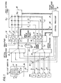
- the wavelength division optical switching system generally comprises an optical multiplexer 10, an optical demultiplexer 20, and a switching network comprising an incoming wavelength switching stage 30, a space switching stage 40 and an outgoing wavelength switching stage 50.
- the switching network is controlled by a central processor 60.
- Optical multiplexer 10 has input waveguides coupled respectively via beam splitters 1, 2, 3 and 4 to subscriber terminal station sets A, B, C and D having assigned wavelengths Xl, ⁇ 2, X3 and X4 respectively. If the switching system is an intermediate or tandem office of an optical communications network, incoming multiplexed light signals from other wavelength division optical switching systems are supplied from their outgoing wavelength switching stages to the incoming wavelength switching stage 30. Incoming light signals from the subscriber stations are sent on the respectively assigned wavelength divided channels and multiplexed by multiplexer 10 into a wavelength-division multiplexed light signal which is conducted through an incoming waveguide, or wavelength division multiplexed highway 12 to a wavelength selector-converter 13 of the incoming wavelength switching stage 30. Incoming wavelength switching stage 30 comprises wavelength selector-converters 14 and 15 which are connected through incoming wavelength division multiplexed highways from other optical multiplexers, not shown, of construction identical to the multiplexer 10 or from other wavelength switching systems via optical transmission mediums.
- Space switching stage 40 is made up of a matrix array of crosspoint switching devices or wavelength selectors 16 ij . (where i and j are row and column numbers respectively) provided at the crosspoints between rows of incoming waveguides i l , i 2 and i3 connected respectively to the outputs of wavelength selector-converters 13, 14 and 15 and columns of output light waveguides j1, j 2 and j 3 which are connected respectively to inputs of wavelength selector-converters 17, 18 and 19 of the outgoing wavelength switching stage 50.
- wavelength selector-converter 17 is connected by a waveguide, or outgoing highway 21 to the input of optical demultiplexer 20.
- the outputs of wavelength selector-converters 18 and 19 are connected to other optical demultiplexers, not shown, which are associated respectively with the other optical multiplexers mentioned above, or connected to the incoming wavelength switching stage or stages of other wavelength switching systems, not shown.
- Demultiplexer 20 has output waveguides connected respectively by outgoing optical waveguides to the subscriber terminal stations A, B, C and D. Thus, a full-duplex light communication path is provided between subscribers to the switching system.
- a switching control signal including the logical address of a destination station is sent on the incoming path of a source station to the central processor 60 where it is translated into a physical address of the destination station. Knowing the physical address of the source station, the central processor 60 performs a path-finding operation with which a connection is established through the switching network between the source and destination stations.
- the central processor 60 includes a well-known common channel signaling function which interacts with an adjacent wavelength division switching system through common-channel signaling paths 28.
- the path-finding operation involves the selection of one of wavelength selector-converters 13-15 in accordance with the physical address location of the source station, the switching of the source-station wavelength division multiplexed channel to one of a plurality of space-stage wavelength division multiplexed channels by the selected wavelength selector-converter, the selection of one of wavelength selector-converters 17-19 in accordance with the physical address of the destination station and the switching of the space-stage wavelength division multiplexed channel to the destination-station channel by the one of wavelength selector-converters 17-19 which is selected.
- the space switching stage 40 has four space-stage wavelength division multiplexed channels available for each crosspoint to allow it to be shared by four simultaneous connections.
- the space switch 40 operates in a wavelength divided fashion, independently of the external wavelength-division multiplexed links.
- each crosspoint of the space switching stage 40 has the same wavelengths ⁇ 1, ⁇ 2, ⁇ 3 and X4 as the terminal wavelength channels.
- the number of space-stage wavelength division multiplexed channels does not have to coincide with the number of external wavelength division multiplexed channels.
- the path-finding operation further involves the selection of one of the crosspoint wavelength selectors 16 ij depending on the physical addresses of the source and destination stations and the determination of an idle channel wavelength based on a switching control algorithm well known in the telephone switching art.
- the selection of wavelength selector-converters 13-15 and the wavelength conversion to the space-switch wavelength division multiplexed channel are accomplished by control data supplied on a control bus 22 from central processor 60.
- the selection of wavelength selector-converters 17-19 and the wavelength conversion to the destination wavelength are accomplished by control iata on a control bus 23.
- the selection of crosspoint wavelength selectors 16 and the determination of a space-switch wavelength division multiplexed channel are provided by control data supplied on control bus 24.
- the switching system further includes a reference Light generator 70 which supplies a plurality of reference lightwaves of different wavelengths on a light waveguide 25 to a beam splitter 80.
- Light generator 70 comprises reference light sources 26 which generate reference lightwaves which are strictly controlled at standard wavelengths Xl, ⁇ 2, ⁇ 3 and X4, respectively, which are multiplexed by an optical multiplexer 27 into the waveguide 25.
- Beam splitter 80 distributes the multiplexed reference lightwaves to the wavelength selector-converters 13-15 and 17-19, respectively, so that each wavelength selector-converter is supplied with lightwaves at wavelengths ⁇ 1, X2, X3 and X4 as carriers.
- Each of the wavelength selector-converters 13-15 and 17-19 is constructed as shown in Fig. 2.
- Each wavelength selector-converter comprises a first array of wavelength selectors 31, 32, 33 and 34 each having a first and a second light waveguide.
- the first waveguides of these wavelength selectors are connected in series to a common light waveguide which may be coupled from the multiplexer 10 or from the space switching stage 40 and the second waveguides of selectors 31, 32, 33 and 34 are respectively connected to first inputs of wavelength converters 35, 36, 37 and 38.
- Such wavelength selectors can be constructed of a known electrooptical switch which directs the flow of light on a substrate of lithium niobate crystal.
- the light is confined to waveguides in the substrate defined by a surrounding material of lower refractive index.
- the first waveguide interacts with the second output waveguide and the light transfers thereinto. If a proper voltage is applied, light remains in the first waveguide.
- Wavelength selectors 31-34 have control terminals which receive wavelength selection control signals of appropriate voltage from the central processor 60 to cause the incoming light signal at one of the wavelengths ⁇ 1 to X4 to be switched to one of the wavelength converters 35-38.
- Wavelength converters 35-38 effect the conversion of any wavelength to wavelengths Xl, X2, X3 and ⁇ 4, respectively, and supply their outputs to an optical multiplexer 39. Details of the wavelength converters will be described later.
- wavelength selector 33 If it is desired to convert wavelength ⁇ 1 to ⁇ 2, for example, it is necessary to activate the wavelength selector 33 with a Xl selection voltage to switch a wavelength-Xl signal to the wavelength converter 36 which converts it to wavelength X2. If it is desired to convert wavelength Xl to X3, the wavelength selector 32 is to be activated with a ⁇ 1-selection voltage to switch the wavelength Xl input to the wavelength converter 37 which converts it to wavelength X3. Thus, if it is desired to convert wavelength X2 to ⁇ 3, the wavelength selector 32 is activated with a X2-selection voltage.
- each wavelength selector-converter is a second array of wavelength selectors 41, 42, 43 and 44 which are identical in construction to wavelength selectors 31, 32, 33 and 34.
- Wavelength selectors 31-34 have their control terminals respectively biased at different DC voltages supplied from a DC voltage source 45.
- the first waveguides of wavelength selectors 41-44 are connected in series to the associated output of the beam splitter 80 and the second waveguides of the selectors are connected respectively to second inputs of the wavelength converters 35, 36, 37 and 38.
- Wavelength selectors 41, 42, 43 and 44 are constantly activated with ⁇ 1, ⁇ 2, X3 and X4 selection DC voltages, so that they selectively switch the wavelength components ⁇ 1, X2 X3 and ⁇ 4 of the multiplexed reference light to second inputs of wavelength converters 35, 36, 37 and 38, respectively.
- each crosspoint wavelength selector 16 of the space switching stage 40 is shown as comprising an array of wavelength selectors, or electrooptical switches 51, 52, 53 and 54 identical in construction to the wavelength selectors 31-34.
- the first waveguides of selectors 51-54 are connected in series in the light waveguide of the "i-th" row of the switch matrix and the second waveguides of these selectors are connected in series to a first input 56 an optical multiplexer 55 ij .
- Multiplexer 55ij has a second input 57 to which multiplexers 55 of the "j-th" column of the switch matrix are connected and provides a multiplexed light signal to the second input of a multiplexer 55 (i-1)j .
- the control terminals of selectors 51-54 are supplied with wavelength selection voltages from the central processor 60 to switch one or more of the incoming wavelengths ⁇ 1, X2, X3 and X4 to the multiplexer 55 ij . In the illustrated embodiment, therefore, a maximum of four different wavelength signals can be switched simultaneously through each crosspoint.
- Fig. 1 Before going into the details of the wavelength converters 34-38, it is appropriate to briefly describe the operation of the wavelength switching system of the invention with reference to Fig. 1.
- terminal station A desires to set up a connection to terminal station C.
- the logical address, or telephone number, of the destination station C is sent from source station A to the processor 60 which translates it into a physical location of the destination station C in terms of the location of wavelength selector-converter 17 and the wavelength X3 of destination station C.
- the processor 60 has the knowledge of the physical location of the source station A in terms of the location of wavelength selector-converter 13 and the wavelength Xl of source station A.
- Central processor 60 proceeds with the determination of an idle channel wavelength.
- the processor 60 supplies a control signal on control bus 22 which will cause the wavelength selector-converter 13 to activate its selector 33, Fig. 2, with a wavelength-Xl selection voltage, thus allowing the wavelength ⁇ 1 signal from the station A to be passed through selector 33 to the wavelength converter 36 and converted to a wavelength ⁇ 2 signal, which is passed through multiplexer 39 to incoming waveguide i 1 of space switching stage 40.
- a wavelength selection signal is supplied on control bus 24 to the crosspoint wavelength selector 16 13 of space switching stage 40 so that one of the wavelength selectors, say, 52 (Fig.
- the return path of the connection can be established between stations C and A as indicated by a chain-dot line using a switching wavelength ⁇ 4, for example.
- wavelengths Xl and X3 are multiplexed on each of the waveguides 12 and 21 and wavelengths X2 and ⁇ 4 are multiplexed on the waveguide between wavelength selector-converters 13 and 17 through the crosspoint 16 13 .
- the wavelength selector-converter of Fig. 2 can be alternatively modified as shown in Fig. 3.
- the wavelength selectors 31-34 are biased with Xl-, ⁇ 2-, X3- and ⁇ 4-selection DC voltages, respectively, to switch signal wavelengths Xl, X2, X3 and X4 respectively in fixed relationship to the wavelength converters 35-38 and the wavelength selectors 41-44 are supplied with wavelength selection control voltages. Therefore, the reference wavelengths are selectively applied to wavelength converters 35-38 in response to the control signal on bus 22 or 23.
- This wavelength converter comprises an optoelectrical converter 61, an electric amplifier 62 and a light modulator 63.
- the light outputs of wavelength switching stages 30 and 50 maintain their wavelengths to the reference values determined exclusively by the reference light sources 26. If the wavelengths of the reference light sources 26 are strictly controlled to close tolerances, the reference light generator 70 eliminates undesirable wavelength deviations which would otherwise cause interchannel crosstalk.
- Fig. 6 is a modified embodiment of the wavelength converter.
- the converter comprises a wavelength filter 71, a nonlinear optical device 72 and an optical band-pass filter 73.
- the wavelength Xi modulating signal and wavelength Xr reference light are directed on waveguides 74 and 75, respectively, at 90 degrees to each other to the wavelength filter 71 so that the modulating light signal is passed to the nonlinear optical device 72 and the reference light beam is reflected at right angles on a reflecting plane 76 to the nonlinear optical device 72.
- the two light beams are combined through a waveguide 77 to the optical device 72.
- Nonlinear optical device 72 has a nonlinear transmissivity as a function of input light intensity, or differential gain characteristic as shown in Fig. 7.
- the intensity of light passing through the nonlinear optical device 72 varies with the modulating signal.
- the modulated output of nonlinear optical device 72 contains the wavelength components of both optical inputs which propagate through optical band-pass filter 73 and only the reference light component is passed through it to the multiplexer 39. This embodiment is advantageous in that it eliminates the need for optoelectrical conversion.
- the modulating and reference light inputs are supplied through waveguides 83 and 84 respectively, so that the modulating light pases through a wavelength filter 81 and enters the nonlinear optical device 82 and the reference light propagates through the device 82 in opposite direction to the direction of propagation of the mondulating light.
- the reference light is modulated with the modulating input as it propagates through the nonlinear optical device 82 and and emerges through the opposite plane and is reflected by filter 81 into waveguide 85 which is coupled to multiplexer 39.
- the wavelength filter 81 may be replaced with a beam splitter 91 as shown in Fig. 9.
- the present invention can be advantangeously employed in a switched communications network as illustrated in Fig. 10 in which three wavelength-division multiplexed switching systems 100, 101 and 102 are shown interconnected by optical transmission lines 103 which data and control signals are transmitted.
- Reference light generator 70 is provided as a common light source which may be installed in the same location with one of the switching systems 100, 101 and 102.
- the reference lightwaves at wavelengths Xl, X2, X3 and X4 are multiplexed and directed on separate optical transmission mediums 104, 105 and 106, respectively, to switching systems 100, 101 and 102.
- Each of the switching systems includes beam splitter 80 which distributes the reference lightwaves to their wavelength switching stages. In this way, the wavelengths of all optical channels of the communications network can be maintained to common reference light sources.
Landscapes
- Engineering & Computer Science (AREA)
- Computer Networks & Wireless Communication (AREA)
- Optical Communication System (AREA)
- Use Of Switch Circuits For Exchanges And Methods Of Control Of Multiplex Exchanges (AREA)
Abstract
Description
- The present invention relates to an optical switching system, and more particularly to a wavelength division optical switching system and a communications network comprising such optical switching systems.
- The recent introduction of optical fiber cables to communications networks have resulted in the need for developing optical switching systems which provide direct switching of light signals sent on optical transmission mediums. Due to the absence of the need for converting the light signals to electrical signals, optical switching systems are economically advantageous over electrical switching systems which are currently implemented by stored program controlled electronic switching systems.
- Since different wavelengths of light can be regarded as a resource for creating transmission channels for carrying light signals, wavelength division multiplexing can multiply the number of channels that can be carried over a single optical fiber. Therefore, if wavelength division multiplexed light signals are transmitted between switching systems, it is desirable to make them directly handle such multiplexed signals to eliminate the need for wavelength division demultiplexers at the interface between a transmission line and a switching system.
- A wavelength division optical switching system is described in Japanese Patent Publication 58-196796. The known optical switching system comprises optical multiplexers each multiplexing incoming light signals which are carried on different wavelength divided channels. The multiplexed signals are applied to a switching network which comprises an incoming wavelength switch, a space switch and an outgoing wavelength switch. The space switch comprises an array of crosspoints each having a plurality of space switch wavelength divided channels so that the space switich can operate as a wavelength divided fashion. Each of the wavelength switches includes an array of wavelength converters each of which converts the wavelength of a signal to a desired wavelength. A wavelength converter of the incoming wavelength switch converts the wavelength of a source terminal signal to an available space switch wavelength of a particular crosspoint. A wavelength converter of the outgoing wavelength switch converts the space switch wavelength to the wavelength of a destination terminal, so that the wavelength divided channel of the source station is switched to the wavelength divided channel of the destination station. The wavelength-switched multiplexed light signals are applied to an optical demultiplexer where they are demultiplexed into the terminals to establish a connection. Each of the wavelength converters can be implemented by a combination of a nonlinear optical device such as lithium niobate crystal for converting any of the wavelengths of the incoming signals to a fixed wavelength which is shorter than any of the wavelengths assigned to the terminals and an optical detector and a light-emitting diode (as described in article "p=n-p-n Optical Detectors and Light-Emitting Diodes", pages 810 to 813, IEEE Journal of Quantum Electronics, Vol. QE-14, No. 11, November 1978) for converting the fixed wavelength to any of the assigned wavelengths. The use of the lithium niobate crystal is due to the fact that the p-n-p-n optical detectors and light-emitting diodes are not capable of converting wavelengths to shorter ones.
- However, the above-mentioned wavelength converter suffers from wavelength instability resulting from difficulty in strictly controlling the proportions of component materials within close manufacturing tolerances and further suffers from temperature dependent wavelength instability. Deviations of wavelengths from those intended are likely to produce crosstalk between adjacent wavelength divided channels, which could lead to a malfunction of switching operations.
- Accordingly, an object of the present invention is to provide a wavelength division optical switching system and a communications network formed by such switching systems which are free from interchannel crosstalk.
- The freedom from crosstalk is achieved by the use of light modulation techniques for conversion of light wavelengths. A reference light generator generates a plurality of reference, or constant intensity lightwaves of different wavelengths which are controlled within close tolerances. The reference lightwaves are used as "carriers" for optical modulating devices to be modulated in intensity with light signals. The use of common source of reference light carriers enables the individual channel wavelengths to be easily and precisely controlled. Preferably, the optical modulator comprises a nonlinear optical device having a nonlinear input-to-output characteristic.
- According to a first aspect of the present invention, a optical switching system comprises an incoming highway to which a wavelength division multiplexed incoming channels of light signals are applied and an outgoing highway from which wavelength division multiplexed outgoing channels of light signals are delivered. A processor identifies an incoming channel on the incoming highway requesting a connection and an outgoing channel on the outgoing highway to which the connection is to be set up. A reference light generator is provided for generating a plurality of reference lightwaves of different wavelengths. A wavelength switch is connected to incoming and outgoing highways for selecting the light signal of the identified incoming channel and modulating the intensity of one of the reference lightwaves in accordance with the selected light signal such that the identified incoming channel is switched to the identified outgoing channel.
- According to a second aspect of the present invention, the wavelength division optical switching system comprises a plurality of terminals each generating a light signal on a particular wavelength divided channel and an optical multiplexer connected to the terminals for multiplexing light signals from the terminals among which a connection is to be set up. A processor identifies a source terminal requesting a connection and a destination terminal to which the connection is to be set up. A reference light generator generates a plurality of reference lightwaves of different wavelengths. A wavelength switch is provided for switching wavelength division multiplexed channels by selecting the identified channel of the source terminal and modulating the intensity of one of the reference lightwaves with the light signal of the selected channel so that the channel of the source terminal is switched to the channel of the destination terminal. An optical demultiplexer is connected to the output of the wavelength switch for demultiplexing the switched wavelength division multiplexed channels and applying the demultiplexed channels to the terminals, respectively.
- According to a third aspect of the invention, there is provided an optical communications network having a plurality of interconnected switching systems. The network comprises a common reference light generating means including means for generating a plurality of reference lightwaves having different wavelengths, and optical transmission mediums for directing the reference beams to each of the switching systems. Each of the switching systems comprises an incoming highway to which a wavelength division multiplexed incoming channels of light signals are applied and an outgoing highway from which wavelength division multiplexed outgoing channels of light signals-are delivered. A processor identifies an incoming channel on the incoming highway channel requesting a connection and an outgoing channel on the outgoing highway to which the connection is to be set up. A wavelength switch is provided for selecting the light signal of the identified incoming channel and modulating the intensity of one of the directed reference lightwaves in accordance with the selected light signal so that the identified incoming channel is switched to the identified outgoing channel.
- The present invention will be described in further detail with reference to the accompanying drawings, in which:
- Fig. 1 is a block diagram of a wavelength division optical switching system of the present invention;
- Fig. 2 is a circuit diagram of a wavelength selector-converter of Fig. 1;
- Fig. 3 is a circuit diagram of an alternative form of the wavelength selector-converter;
- Fig..4 is a circuit diagram of a space switch wavelength selector of Fig. 1;
- Fig. 5 is a diagram of an electrooptical implementation of a wavelength converter of Figs. 2 and 3;
- Fig. 6 is a diagram of an optical implementation of the wavelength converter using a nonlinear optical device;
- Fig. 7 is a graphic illustration of the nonlinear operating characteristic of the nonlinear optical device;
- Figs. 8 and 9 are illustrations of modified forms of the wavelength converter; and
- Fig. 10 is a block diagram of a wavelength division switched optical communications network embodying the present invention.
- Referring to Fig. 1, there is shown a preferred embodiment of a wavelength division optical switching system of the present invention. The wavelength division optical switching system generally comprises an
optical multiplexer 10, anoptical demultiplexer 20, and a switching network comprising an incomingwavelength switching stage 30, aspace switching stage 40 and an outgoingwavelength switching stage 50. The switching network is controlled by acentral processor 60. -
Optical multiplexer 10 has input waveguides coupled respectively viabeam splitters wavelength switching stage 30. Incoming light signals from the subscriber stations are sent on the respectively assigned wavelength divided channels and multiplexed bymultiplexer 10 into a wavelength-division multiplexed light signal which is conducted through an incoming waveguide, or wavelength division multiplexedhighway 12 to a wavelength selector-converter 13 of the incomingwavelength switching stage 30. Incomingwavelength switching stage 30 comprises wavelength selector-converters multiplexer 10 or from other wavelength switching systems via optical transmission mediums. -
Space switching stage 40 is made up of a matrix array of crosspoint switching devices or wavelength selectors 16ij. (where i and j are row and column numbers respectively) provided at the crosspoints between rows of incoming waveguides il, i2 and i3 connected respectively to the outputs of wavelength selector-converters converters wavelength switching stage 50. - The output of wavelength selector-
converter 17 is connected by a waveguide, or outgoing highway 21 to the input ofoptical demultiplexer 20. The outputs of wavelength selector-converters - A switching control signal including the logical address of a destination station is sent on the incoming path of a source station to the
central processor 60 where it is translated into a physical address of the destination station. Knowing the physical address of the source station, thecentral processor 60 performs a path-finding operation with which a connection is established through the switching network between the source and destination stations. - For interoffice or tandem switching, the
central processor 60 includes a well-known common channel signaling function which interacts with an adjacent wavelength division switching system through common-channel signaling paths 28. - As will be understood as the description proceeds, the path-finding operation involves the selection of one of wavelength selector-converters 13-15 in accordance with the physical address location of the source station, the switching of the source-station wavelength division multiplexed channel to one of a plurality of space-stage wavelength division multiplexed channels by the selected wavelength selector-converter, the selection of one of wavelength selector-converters 17-19 in accordance with the physical address of the destination station and the switching of the space-stage wavelength division multiplexed channel to the destination-station channel by the one of wavelength selector-converters 17-19 which is selected. In the illustrated embodiment, the
space switching stage 40 has four space-stage wavelength division multiplexed channels available for each crosspoint to allow it to be shared by four simultaneous connections. In effect, thespace switch 40 operates in a wavelength divided fashion, independently of the external wavelength-division multiplexed links. For purposes of illustration, each crosspoint of thespace switching stage 40 has the same wavelengths \1, \2, λ3 and X4 as the terminal wavelength channels. The number of space-stage wavelength division multiplexed channels does not have to coincide with the number of external wavelength division multiplexed channels. The path-finding operation further involves the selection of one of the crosspoint wavelength selectors 16ij depending on the physical addresses of the source and destination stations and the determination of an idle channel wavelength based on a switching control algorithm well known in the telephone switching art. - The selection of wavelength selector-converters 13-15 and the wavelength conversion to the space-switch wavelength division multiplexed channel are accomplished by control data supplied on a
control bus 22 fromcentral processor 60. The selection of wavelength selector-converters 17-19 and the wavelength conversion to the destination wavelength are accomplished by control iata on acontrol bus 23. The selection of crosspoint wavelength selectors 16 and the determination of a space-switch wavelength division multiplexed channel are provided by control data supplied oncontrol bus 24. - The switching system further includes a
reference Light generator 70 which supplies a plurality of reference lightwaves of different wavelengths on alight waveguide 25 to abeam splitter 80.Light generator 70 comprises referencelight sources 26 which generate reference lightwaves which are strictly controlled at standard wavelengths Xl, λ2, λ3 and X4, respectively, which are multiplexed by anoptical multiplexer 27 into thewaveguide 25.Beam splitter 80 distributes the multiplexed reference lightwaves to the wavelength selector-converters 13-15 and 17-19, respectively, so that each wavelength selector-converter is supplied with lightwaves at wavelengths λ1, X2, X3 and X4 as carriers. - Each of the wavelength selector-converters 13-15 and 17-19 is constructed as shown in Fig. 2. Each wavelength selector-converter comprises a first array of
wavelength selectors multiplexer 10 or from thespace switching stage 40 and the second waveguides ofselectors wavelength converters - Wavelength selectors 31-34 have control terminals which receive wavelength selection control signals of appropriate voltage from the
central processor 60 to cause the incoming light signal at one of the wavelengths λ1 to X4 to be switched to one of the wavelength converters 35-38. Wavelength converters 35-38 effect the conversion of any wavelength to wavelengths Xl, X2, X3 and λ4, respectively, and supply their outputs to anoptical multiplexer 39. Details of the wavelength converters will be described later. - If it is desired to convert wavelength λ1 to λ2, for example, it is necessary to activate the
wavelength selector 33 with a Xl selection voltage to switch a wavelength-Xl signal to thewavelength converter 36 which converts it to wavelength X2. If it is desired to convert wavelength Xl to X3, thewavelength selector 32 is to be activated with a λ1-selection voltage to switch the wavelength Xl input to thewavelength converter 37 which converts it to wavelength X3. Thus, if it is desired to convert wavelength X2 to λ3, thewavelength selector 32 is activated with a X2-selection voltage. - Further included in each wavelength selector-converter is a second array of
wavelength selectors wavelength selectors DC voltage source 45. The first waveguides of wavelength selectors 41-44 are connected in series to the associated output of thebeam splitter 80 and the second waveguides of the selectors are connected respectively to second inputs of thewavelength converters Wavelength selectors wavelength converters - Referring to Fig. 4, each crosspoint wavelength selector 16 of the
space switching stage 40 is shown as comprising an array of wavelength selectors, orelectrooptical switches first input 56 an optical multiplexer 55ij. Multiplexer 55ij has asecond input 57 to which multiplexers 55 of the "j-th" column of the switch matrix are connected and provides a multiplexed light signal to the second input of a multiplexer 55(i-1)j. The control terminals of selectors 51-54 are supplied with wavelength selection voltages from thecentral processor 60 to switch one or more of the incoming wavelengths λ1, X2, X3 and X4 to the multiplexer 55ij. In the illustrated embodiment, therefore, a maximum of four different wavelength signals can be switched simultaneously through each crosspoint. - Before going into the details of the wavelength converters 34-38, it is appropriate to briefly describe the operation of the wavelength switching system of the invention with reference to Fig. 1. Assume that terminal station A desires to set up a connection to terminal station C. The logical address, or telephone number, of the destination station C is sent from source station A to the
processor 60 which translates it into a physical location of the destination station C in terms of the location of wavelength selector-converter 17 and the wavelength X3 of destination station C. Simultaneously, theprocessor 60 has the knowledge of the physical location of the source station A in terms of the location of wavelength selector-converter 13 and the wavelength Xl of source stationA. Central processor 60 proceeds with the determination of an idle channel wavelength. If wavelength X2 is selected for a crosspoint of thespace switching stage 40, theprocessor 60 supplies a control signal oncontrol bus 22 which will cause the wavelength selector-converter 13 to activate itsselector 33, Fig. 2, with a wavelength-Xl selection voltage, thus allowing the wavelength λ1 signal from the station A to be passed throughselector 33 to thewavelength converter 36 and converted to a wavelength λ2 signal, which is passed throughmultiplexer 39 to incoming waveguide i1 ofspace switching stage 40. A wavelength selection signal is supplied oncontrol bus 24 to the crosspoint wavelength selector 1613 ofspace switching stage 40 so that one of the wavelength selectors, say, 52 (Fig. 4) is activated with a X2 selection voltage to cause the wavelength-λ2 signal to be switched to theinput 56 of multiplexer 5513. Simultaneously, another control signal is supplied oncontrol bus 23 to the wavelength selector-converter 17 ofwavelength switch 50 to activate itsselector 32 with a wavelength-λ2 selection voltage to cause the wavelength-X2 signal from crosspoint 1613 to be switched to thewavelength converter 37 and converted to a wavelength-X3 signal which is applied throughmultiplexer 39 of wavelength selector-converter 17 todemultiplexer 20 and thence to destination station C, thus establishing a go-path connection between stations A and C as indicated by a dotted line. In a similar manner, the return path of the connection can be established between stations C and A as indicated by a chain-dot line using a switching wavelength λ4, for example. As a result, wavelengths Xl and X3 are multiplexed on each of thewaveguides 12 and 21 and wavelengths X2 and λ4 are multiplexed on the waveguide between wavelength selector-converters - It will be seen from the above description that the wavelength selector-converter of Fig. 2 can be alternatively modified as shown in Fig. 3. In this modification, the wavelength selectors 31-34 are biased with Xl-, λ2-, X3- and λ4-selection DC voltages, respectively, to switch signal wavelengths Xl, X2, X3 and X4 respectively in fixed relationship to the wavelength converters 35-38 and the wavelength selectors 41-44 are supplied with wavelength selection control voltages. Therefore, the reference wavelengths are selectively applied to wavelength converters 35-38 in response to the control signal on
bus - Details of the wavelength converters 35-38 and the function of wavelength selectors 41-44 in relation to converters 35-38 will now be described with reference to Figs. 5 to 9. In Fig. 5, one embodiment of the wavelength converter is illustrated. This wavelength converter comprises an optoelectrical converter 61, an
electric amplifier 62 and alight modulator 63. The converter 61 is associated with one of wavelength selectors 31-34 throughwaveguide 64 to convert a light signal at wavelength Xi (where i=l, 2, 3 or 4) to an electrical signal which is amplified byamplifier 62 and applied tolight modulator 63 as a modulating electrical signal. A reference lightwave is conducted from an associated one of the wavelength selectors 41-44 through awaveguide 65 to thelight modulator 63 and so the reference light at wavelength λr (where r=l, 2, 3 or 4) is modulated in intensity with the signal and emerges throughwaveguide 66 tomultiplexer 39. As a result of the light modulation, the light outputs ofwavelength switching stages reference light sources 26. If the wavelengths of thereference light sources 26 are strictly controlled to close tolerances, thereference light generator 70 eliminates undesirable wavelength deviations which would otherwise cause interchannel crosstalk. - Fig. 6 is a modified embodiment of the wavelength converter. In this modification, the converter comprises a
wavelength filter 71, a nonlinearoptical device 72 and an optical band-pass filter 73. The wavelength Xi modulating signal and wavelength Xr reference light are directed onwaveguides 74 and 75, respectively, at 90 degrees to each other to thewavelength filter 71 so that the modulating light signal is passed to the nonlinearoptical device 72 and the reference light beam is reflected at right angles on a reflectingplane 76 to the nonlinearoptical device 72. The two light beams are combined through awaveguide 77 to theoptical device 72. Nonlinearoptical device 72 has a nonlinear transmissivity as a function of input light intensity, or differential gain characteristic as shown in Fig. 7. If the reference light has intensity Pl and the modulating light oscillates with an amplitude P3, the intensity of light passing through the nonlinearoptical device 72 varies with the modulating signal. The modulated output of nonlinearoptical device 72 contains the wavelength components of both optical inputs which propagate through optical band-pass filter 73 and only the reference light component is passed through it to themultiplexer 39. This embodiment is advantageous in that it eliminates the need for optoelectrical conversion. - Alternatively, in Fig. 8, the modulating and reference light inputs are supplied through
waveguides wavelength filter 81 and enters the nonlinearoptical device 82 and the reference light propagates through thedevice 82 in opposite direction to the direction of propagation of the mondulating light. The reference light is modulated with the modulating input as it propagates through the nonlinearoptical device 82 and and emerges through the opposite plane and is reflected byfilter 81 intowaveguide 85 which is coupled tomultiplexer 39. Alternatively, thewavelength filter 81 may be replaced with abeam splitter 91 as shown in Fig. 9. - The present invention can be advantangeously employed in a switched communications network as illustrated in Fig. 10 in which three wavelength-division multiplexed switching
systems optical transmission lines 103 which data and control signals are transmitted.Reference light generator 70 is provided as a common light source which may be installed in the same location with one of the switchingsystems optical transmission mediums systems - Each of the switching systems includes
beam splitter 80 which distributes the reference lightwaves to their wavelength switching stages. In this way, the wavelengths of all optical channels of the communications network can be maintained to common reference light sources. - The foregoing description shows only preferred embodiments of the present invention. Various modifications are apparent to those skilled in the art without departing from the scope of the present invention which is only limited by the appended claims.
Claims (17)
Applications Claiming Priority (4)
| Application Number | Priority Date | Filing Date | Title |
|---|---|---|---|
| JP264342/85 | 1985-11-22 | ||
| JP60264342A JPS62123898A (en) | 1985-11-22 | 1985-11-22 | Wavelength multiplex light switchboard and wavelength multiplex light communication network |
| JP209008/86 | 1986-09-04 | ||
| JP61209008A JPS6364035A (en) | 1986-09-04 | 1986-09-04 | Light wavelength converting circuit |
Publications (3)
| Publication Number | Publication Date |
|---|---|
| EP0223258A2 true EP0223258A2 (en) | 1987-05-27 |
| EP0223258A3 EP0223258A3 (en) | 1989-04-19 |
| EP0223258B1 EP0223258B1 (en) | 1994-01-26 |
Family
ID=26517171
Family Applications (1)
| Application Number | Title | Priority Date | Filing Date |
|---|---|---|---|
| EP86116132A Expired - Lifetime EP0223258B1 (en) | 1985-11-22 | 1986-11-21 | Wavelength division optical switching system having wavelength switching light modulators |
Country Status (4)
| Country | Link |
|---|---|
| US (1) | US4845703A (en) |
| EP (1) | EP0223258B1 (en) |
| CA (1) | CA1274612A (en) |
| DE (1) | DE3689583T2 (en) |
Cited By (9)
| Publication number | Priority date | Publication date | Assignee | Title |
|---|---|---|---|---|
| EP0317352A1 (en) * | 1987-11-20 | 1989-05-24 | BRITISH TELECOMMUNICATIONS public limited company | Switched optical network |
| GB2223138A (en) * | 1987-04-13 | 1990-03-28 | Kollmorgen Corp | Optical multiplexing system |
| EP0467764A1 (en) * | 1990-07-17 | 1992-01-22 | France Telecom | Optical switching system for frequency multiplexed signals |
| EP0494831A2 (en) * | 1991-01-10 | 1992-07-15 | Fujitsu Limited | Optical processing device with wavelength stabilization and optical switch using such a device |
| EP0581888A1 (en) * | 1991-04-22 | 1994-02-09 | The Trustees Of Columbia University In The City Of New York | Optical communications system and method |
| FR2709839A1 (en) * | 1993-09-10 | 1995-03-17 | Loualiche Slimane | Switch for switching optical signals |
| GB2303010A (en) * | 1995-07-05 | 1997-02-05 | France Telecom | Frequency transposition of optical signals |
| US5657144A (en) * | 1991-01-10 | 1997-08-12 | Fujitsu Limited | Optical processing device operating in a wavelength-synchronized mode and an optical circuit exchanger that uses such an optical processing device |
| EP1079571A2 (en) * | 1999-08-25 | 2001-02-28 | Nippon Telegraph and Telephone Corporation | Optical packet routing network system based on optical label switching technique |
Families Citing this family (26)
| Publication number | Priority date | Publication date | Assignee | Title |
|---|---|---|---|---|
| DE3853935T2 (en) * | 1987-09-30 | 1995-10-12 | Nippon Electric Co | Time and wavelength division multiplexed switching system. |
| JP2595025B2 (en) * | 1988-03-18 | 1997-03-26 | 株式会社日立製作所 | High-speed packet switching equipment using space division type switches |
| JPH0267525A (en) * | 1988-09-02 | 1990-03-07 | Hitachi Ltd | Optical switching device and inter-switch transmission method |
| GB8902745D0 (en) * | 1989-02-08 | 1989-03-30 | British Telecomm | Optical interconnection network |
| JPH0357343A (en) * | 1989-07-26 | 1991-03-12 | Oki Electric Ind Co Ltd | Optical exchange |
| IT1233075B (en) * | 1989-08-01 | 1992-03-14 | Cselt Centro Studi Lab Telecom | FAST PACKAGE AND FREQUENCY SWITCH |
| US5274487A (en) * | 1989-12-29 | 1993-12-28 | Fujitsu Limited | Photonic switching system |
| JPH0410722A (en) * | 1990-04-27 | 1992-01-14 | Hitachi Ltd | Coherent communication method, crossconnecting device and exchange |
| DE4019225A1 (en) * | 1990-06-15 | 1991-12-19 | Standard Elektrik Lorenz Ag | OPTICAL SWITCHING ELEMENT |
| JP3308525B2 (en) * | 1990-11-30 | 2002-07-29 | 株式会社日立製作所 | network |
| US5915054A (en) * | 1992-03-05 | 1999-06-22 | Fuji Xerox Co., Ltd. | Star coupler for an optical communication network |
| US5233453A (en) * | 1992-04-29 | 1993-08-03 | International Business Machines Corporation | Space-division switched waveguide array filter and method using same |
| JP3204463B2 (en) * | 1992-06-06 | 2001-09-04 | キヤノン株式会社 | WDM optical communication network |
| US5712932A (en) * | 1995-08-08 | 1998-01-27 | Ciena Corporation | Dynamically reconfigurable WDM optical communication systems with optical routing systems |
| DE19605808C2 (en) * | 1996-02-16 | 1997-12-18 | Siemens Ag | WDM coupling arrangement |
| US6570872B1 (en) * | 1999-04-06 | 2003-05-27 | Nortel Networks Limited | Self-configuring distributed switch |
| JP2000341728A (en) * | 1999-05-31 | 2000-12-08 | Fujitsu Ltd | Optical cross connection device |
| JP2002101432A (en) * | 2000-07-21 | 2002-04-05 | Fujitsu Ltd | Optical switch network, optical cross connector and optical branching/inserting device |
| DE10102872C2 (en) * | 2001-01-23 | 2003-07-17 | Infineon Technologies Ag | Computer with high speed bus |
| KR100759167B1 (en) * | 2001-09-04 | 2007-09-14 | 엘지노텔 주식회사 | Optical channel switch for a wavelength division multiplex system, and control method of the switch |
| KR100446534B1 (en) * | 2002-11-22 | 2004-09-01 | 삼성전자주식회사 | Wavelength converter and wavelength interchanging cross-connector using the same |
| US20090034965A1 (en) * | 2004-02-23 | 2009-02-05 | Look Christopher M | Method and an apparatus to automatically verify connectivity within an optical network node |
| US7848644B2 (en) * | 2004-02-23 | 2010-12-07 | Dynamic Method Enterprises Limited | Method and an apparatus to provide optical equipment protection |
| AU2018322489A1 (en) * | 2017-08-25 | 2020-03-12 | Baraja Pty Ltd | Estimation of spatial profile of environment |
| CA3074245A1 (en) | 2017-09-06 | 2019-03-14 | Baraja Pty Ltd | An optical beam director |
| EP3864431A4 (en) * | 2018-10-12 | 2022-06-22 | SiLC Technologies, Inc. | Optical switching in lidar systems |
Citations (4)
| Publication number | Priority date | Publication date | Assignee | Title |
|---|---|---|---|---|
| GB2043240A (en) * | 1979-03-01 | 1980-10-01 | Post Office | Improvements in or relating to the switching of signals |
| EP0131818A2 (en) * | 1983-07-01 | 1985-01-23 | International Standard Electric Corporation | Optical FDM system |
| JPS60172841A (en) * | 1984-01-27 | 1985-09-06 | Nippon Telegr & Teleph Corp <Ntt> | Optical switch |
| EP0264119A2 (en) * | 1986-10-15 | 1988-04-20 | Nec Corporation | An optical wavelength-division switching system |
Family Cites Families (4)
| Publication number | Priority date | Publication date | Assignee | Title |
|---|---|---|---|---|
| FR2224960B1 (en) * | 1973-04-05 | 1975-12-26 | Materiel Telephonique | |
| US4530084A (en) * | 1981-10-08 | 1985-07-16 | Heinrich Hertz Institut Fuer Nachrichten Technik | Communications network with optical channels |
| JPS58202690A (en) * | 1982-05-21 | 1983-11-25 | Nec Corp | Optical multiplex signal switching device |
| JPS59122161A (en) * | 1982-12-28 | 1984-07-14 | Toshiba Corp | Broad band network system |
-
1986
- 1986-11-21 CA CA000523515A patent/CA1274612A/en not_active Expired - Lifetime
- 1986-11-21 DE DE3689583T patent/DE3689583T2/en not_active Expired - Lifetime
- 1986-11-21 EP EP86116132A patent/EP0223258B1/en not_active Expired - Lifetime
- 1986-11-24 US US06/934,573 patent/US4845703A/en not_active Expired - Lifetime
Patent Citations (4)
| Publication number | Priority date | Publication date | Assignee | Title |
|---|---|---|---|---|
| GB2043240A (en) * | 1979-03-01 | 1980-10-01 | Post Office | Improvements in or relating to the switching of signals |
| EP0131818A2 (en) * | 1983-07-01 | 1985-01-23 | International Standard Electric Corporation | Optical FDM system |
| JPS60172841A (en) * | 1984-01-27 | 1985-09-06 | Nippon Telegr & Teleph Corp <Ntt> | Optical switch |
| EP0264119A2 (en) * | 1986-10-15 | 1988-04-20 | Nec Corporation | An optical wavelength-division switching system |
Non-Patent Citations (3)
| Title |
|---|
| FREQUENZ, vol. 36, no. 12, December 1982, pages 319-327, Berlin, DE; M. ROCKS et al.: "Optische Multiplex-Systeme in der optischen Nachrichtentechnik" * |
| IEEE JOURNAL OF QUANTUM ELECTRONICS, vol. QE-20, no. 4, April 1984, pages 332-334, IEEE, New York, US; N.A. OLSSON et al.: "An optical switching and routing system using frequency tunable cleaved-coupled-cavity semiconductor lasers" * |
| PATENT ABSTRACTS OF JAPAN, vol. 10, no. 8 (E-373)[2065], 14th January 1986; & JP-A-60 172 841 (NIPPON DENSHIN DENWA KOSHA) 06-09-1985 * |
Cited By (28)
| Publication number | Priority date | Publication date | Assignee | Title |
|---|---|---|---|---|
| GB2223138A (en) * | 1987-04-13 | 1990-03-28 | Kollmorgen Corp | Optical multiplexing system |
| WO1989005085A1 (en) * | 1987-11-20 | 1989-06-01 | British Telecommunications Public Limited Company | Switched optical network |
| JPH02502150A (en) * | 1987-11-20 | 1990-07-12 | ブリテツシユ・テレコミユニケイシヨンズ・パブリツク・リミテツド・カンパニー | optical switching network |
| AU617401B2 (en) * | 1987-11-20 | 1991-11-28 | British Telecommunications Public Limited Company | Switched optical network |
| EP0317352A1 (en) * | 1987-11-20 | 1989-05-24 | BRITISH TELECOMMUNICATIONS public limited company | Switched optical network |
| US5144465A (en) * | 1987-11-20 | 1992-09-01 | British Telecommunications Public Limited Company | Switched optical network |
| US5189542A (en) * | 1990-07-17 | 1993-02-23 | France Telecom Etablissement Autonome De Droit Public (Centre National D'etudes Des Telecommunications) | System for the optical switching of frequency multiplexed signals |
| EP0467764A1 (en) * | 1990-07-17 | 1992-01-22 | France Telecom | Optical switching system for frequency multiplexed signals |
| FR2665039A1 (en) * | 1990-07-17 | 1992-01-24 | France Telecom | OPTICAL SWITCHING SYSTEM FOR MULTIPLEX FREQUENCY SIGNALS. |
| EP0923264A3 (en) * | 1991-01-10 | 1999-08-18 | Fujitsu Limited | Optical processing device with wavelength stabilisation and an optical switch using such a device |
| EP0918447A3 (en) * | 1991-01-10 | 1999-08-18 | Fujitsu Limited | Optical processing device with wavelength stabilisation and an optical switch using such a device |
| EP0494831A3 (en) * | 1991-01-10 | 1993-10-27 | Fujitsu Ltd | Optical processing device with wavelength stabilization and optical switch using such a device |
| US5657144A (en) * | 1991-01-10 | 1997-08-12 | Fujitsu Limited | Optical processing device operating in a wavelength-synchronized mode and an optical circuit exchanger that uses such an optical processing device |
| US5715075A (en) * | 1991-01-10 | 1998-02-03 | Fujitsu Limited | Optical processing device operating in a wavelength-synchronized mode and an optical circuit exchanger that uses such an optical processing device |
| EP0494831A2 (en) * | 1991-01-10 | 1992-07-15 | Fujitsu Limited | Optical processing device with wavelength stabilization and optical switch using such a device |
| EP0918447A2 (en) * | 1991-01-10 | 1999-05-26 | Fujitsu Limited | Optical processing device with wavelength stabilisation and an optical switch using such a device |
| EP0923264A2 (en) * | 1991-01-10 | 1999-06-16 | Fujitsu Limited | Optical processing device with wavelength stabilisation and an optical switch using such a device |
| EP0581888A1 (en) * | 1991-04-22 | 1994-02-09 | The Trustees Of Columbia University In The City Of New York | Optical communications system and method |
| EP0581888A4 (en) * | 1991-04-22 | 1994-08-03 | The Trustees Of Columbia University In The City Of New York | |
| FR2709839A1 (en) * | 1993-09-10 | 1995-03-17 | Loualiche Slimane | Switch for switching optical signals |
| GB2303010A (en) * | 1995-07-05 | 1997-02-05 | France Telecom | Frequency transposition of optical signals |
| GB2303010B (en) * | 1995-07-05 | 1999-03-10 | France Telecom | Device for the frequency transposistion of optical signals |
| EP1079571A2 (en) * | 1999-08-25 | 2001-02-28 | Nippon Telegraph and Telephone Corporation | Optical packet routing network system based on optical label switching technique |
| EP1079571A3 (en) * | 1999-08-25 | 2004-03-24 | Nippon Telegraph and Telephone Corporation | Optical packet routing network system based on optical label switching technique |
| US6782210B1 (en) | 1999-08-25 | 2004-08-24 | Nippon Telegraph And Telephone Corporation | Optical packet routing network system based on optical label switching technique |
| EP1499077A1 (en) * | 1999-08-25 | 2005-01-19 | Nippon Telegraph and Telephone Corporation | Optical packet routing network system based on optical label switching technique |
| US7113701B2 (en) | 1999-08-25 | 2006-09-26 | Nippon Telegraph And Telephone Corporation | Optical packet routing network system based on optical label switching technique |
| US7120358B2 (en) | 1999-08-25 | 2006-10-10 | Nippon Telegraph And Telephone Corporation | Optical packet routing network system based on optical label switching technique |
Also Published As
| Publication number | Publication date |
|---|---|
| US4845703A (en) | 1989-07-04 |
| DE3689583T2 (en) | 1994-08-25 |
| DE3689583D1 (en) | 1994-03-10 |
| EP0223258B1 (en) | 1994-01-26 |
| EP0223258A3 (en) | 1989-04-19 |
| CA1274612A (en) | 1990-09-25 |
Similar Documents
| Publication | Publication Date | Title |
|---|---|---|
| US4845703A (en) | Wavelength division optical switching system having wavelength switching light modulators | |
| US6069719A (en) | Dynamically reconfigurable optical add-drop multiplexers for WDM optical communication systems | |
| JP2989269B2 (en) | Cross connection for optical networks | |
| US5739935A (en) | Modular optical cross-connect architecture with optical wavelength switching | |
| AU626985B2 (en) | Communication network | |
| US5623356A (en) | Combined wavelength router and switch apparatus for use in a wavelength division multiplexed optical communication system | |
| US5208691A (en) | Wavelength-time-space division switching system | |
| US5537239A (en) | Optical transmission network with a switching matrix | |
| JPH03219793A (en) | Wavelength division optical exchange | |
| CA1274995A (en) | Optical switching means | |
| US6137608A (en) | Optical network switching system | |
| US5353145A (en) | Optical distributor | |
| JP2763167B2 (en) | Optical switching network | |
| JP2002534932A (en) | Wavelength modular optical cross connect switch | |
| US6445473B1 (en) | Optical switching apparatus using wavelength division multiplexing technology | |
| KR100337801B1 (en) | Optical wavelength-division multiplex transmission network device using transceiver having 2-input/2-output optical path switch | |
| US5657144A (en) | Optical processing device operating in a wavelength-synchronized mode and an optical circuit exchanger that uses such an optical processing device | |
| US7174104B2 (en) | Transmitting apparatus using multiple lambda source in WDM network | |
| JPH09506754A (en) | ATM system compatible 3-stage switching unit | |
| JPH0714228B2 (en) | Time division wavelength division merging type optical switching communication path device | |
| KR100368899B1 (en) | 3-stage switching unit | |
| JPS636993A (en) | Wavelength division type optical exchange system | |
| JPH1066112A (en) | Optical matrix switch | |
| Gaudino et al. | Remote provisioning of a reconfigurable WDM multichannel add/drop multiplexer | |
| JP2658114B2 (en) | Wavelength conversion switch |
Legal Events
| Date | Code | Title | Description |
|---|---|---|---|
| PUAI | Public reference made under article 153(3) epc to a published international application that has entered the european phase |
Free format text: ORIGINAL CODE: 0009012 |
|
| 17P | Request for examination filed |
Effective date: 19861121 |
|
| AK | Designated contracting states |
Kind code of ref document: A2 Designated state(s): DE FR GB NL SE |
|
| PUAL | Search report despatched |
Free format text: ORIGINAL CODE: 0009013 |
|
| AK | Designated contracting states |
Kind code of ref document: A3 Designated state(s): DE FR GB NL SE |
|
| 16A | New documents despatched to applicant after publication of the search report | ||
| 17Q | First examination report despatched |
Effective date: 19910809 |
|
| GRAA | (expected) grant |
Free format text: ORIGINAL CODE: 0009210 |
|
| AK | Designated contracting states |
Kind code of ref document: B1 Designated state(s): DE FR GB NL SE |
|
| PG25 | Lapsed in a contracting state [announced via postgrant information from national office to epo] |
Ref country code: NL Effective date: 19940126 Ref country code: SE Effective date: 19940126 Ref country code: FR Effective date: 19940126 |
|
| REF | Corresponds to: |
Ref document number: 3689583 Country of ref document: DE Date of ref document: 19940310 |
|
| EN | Fr: translation not filed | ||
| NLV1 | Nl: lapsed or annulled due to failure to fulfill the requirements of art. 29p and 29m of the patents act | ||
| PLBE | No opposition filed within time limit |
Free format text: ORIGINAL CODE: 0009261 |
|
| STAA | Information on the status of an ep patent application or granted ep patent |
Free format text: STATUS: NO OPPOSITION FILED WITHIN TIME LIMIT |
|
| 26N | No opposition filed | ||
| REG | Reference to a national code |
Ref country code: GB Ref legal event code: IF02 |
|
| PGFP | Annual fee paid to national office [announced via postgrant information from national office to epo] |
Ref country code: GB Payment date: 20051116 Year of fee payment: 20 |
|
| PGFP | Annual fee paid to national office [announced via postgrant information from national office to epo] |
Ref country code: DE Payment date: 20051117 Year of fee payment: 20 |
|
| PG25 | Lapsed in a contracting state [announced via postgrant information from national office to epo] |
Ref country code: GB Free format text: LAPSE BECAUSE OF EXPIRATION OF PROTECTION Effective date: 20061120 |
|
| REG | Reference to a national code |
Ref country code: GB Ref legal event code: PE20 |