EP0223256A2 - Rear wheel steering apparatus for vehicle - Google Patents
Rear wheel steering apparatus for vehicle Download PDFInfo
- Publication number
- EP0223256A2 EP0223256A2 EP86116116A EP86116116A EP0223256A2 EP 0223256 A2 EP0223256 A2 EP 0223256A2 EP 86116116 A EP86116116 A EP 86116116A EP 86116116 A EP86116116 A EP 86116116A EP 0223256 A2 EP0223256 A2 EP 0223256A2
- Authority
- EP
- European Patent Office
- Prior art keywords
- rear wheel
- steer angle
- wheel steer
- left rear
- steering apparatus
- Prior art date
- Legal status (The legal status is an assumption and is not a legal conclusion. Google has not performed a legal analysis and makes no representation as to the accuracy of the status listed.)
- Granted
Links
Images


Classifications
-
- B—PERFORMING OPERATIONS; TRANSPORTING
- B60—VEHICLES IN GENERAL
- B60G—VEHICLE SUSPENSION ARRANGEMENTS
- B60G7/00—Pivoted suspension arms; Accessories thereof
- B60G7/006—Attaching arms to sprung or unsprung part of vehicle, characterised by comprising attachment means controlled by an external actuator, e.g. a fluid or electrical motor
-
- B—PERFORMING OPERATIONS; TRANSPORTING
- B62—LAND VEHICLES FOR TRAVELLING OTHERWISE THAN ON RAILS
- B62D—MOTOR VEHICLES; TRAILERS
- B62D7/00—Steering linkage; Stub axles or their mountings
- B62D7/06—Steering linkage; Stub axles or their mountings for individually-pivoted wheels, e.g. on king-pins
- B62D7/14—Steering linkage; Stub axles or their mountings for individually-pivoted wheels, e.g. on king-pins the pivotal axes being situated in more than one plane transverse to the longitudinal centre line of the vehicle, e.g. all-wheel steering
- B62D7/15—Steering linkage; Stub axles or their mountings for individually-pivoted wheels, e.g. on king-pins the pivotal axes being situated in more than one plane transverse to the longitudinal centre line of the vehicle, e.g. all-wheel steering characterised by means varying the ratio between the steering angles of the steered wheels
- B62D7/159—Steering linkage; Stub axles or their mountings for individually-pivoted wheels, e.g. on king-pins the pivotal axes being situated in more than one plane transverse to the longitudinal centre line of the vehicle, e.g. all-wheel steering characterised by means varying the ratio between the steering angles of the steered wheels characterised by computing methods or stabilisation processes or systems, e.g. responding to yaw rate, lateral wind, load, road condition
-
- B—PERFORMING OPERATIONS; TRANSPORTING
- B60—VEHICLES IN GENERAL
- B60G—VEHICLE SUSPENSION ARRANGEMENTS
- B60G2200/00—Indexing codes relating to suspension types
- B60G2200/40—Indexing codes relating to the wheels in the suspensions
- B60G2200/44—Indexing codes relating to the wheels in the suspensions steerable
-
- B—PERFORMING OPERATIONS; TRANSPORTING
- B60—VEHICLES IN GENERAL
- B60G—VEHICLE SUSPENSION ARRANGEMENTS
- B60G2200/00—Indexing codes relating to suspension types
- B60G2200/40—Indexing codes relating to the wheels in the suspensions
- B60G2200/462—Toe-in/out
-
- B—PERFORMING OPERATIONS; TRANSPORTING
- B60—VEHICLES IN GENERAL
- B60G—VEHICLE SUSPENSION ARRANGEMENTS
- B60G2204/00—Indexing codes related to suspensions per se or to auxiliary parts
- B60G2204/10—Mounting of suspension elements
- B60G2204/14—Mounting of suspension arms
- B60G2204/143—Mounting of suspension arms on the vehicle body or chassis
-
- B—PERFORMING OPERATIONS; TRANSPORTING
- B60—VEHICLES IN GENERAL
- B60G—VEHICLE SUSPENSION ARRANGEMENTS
- B60G2204/00—Indexing codes related to suspensions per se or to auxiliary parts
- B60G2204/40—Auxiliary suspension parts; Adjustment of suspensions
- B60G2204/419—Gears
- B60G2204/4193—Gears worm gears
Definitions
- the shaft 56 is eccentric with respect to the mutual center C of the worm wheel 48 and the eccentric cams 50 and 56.
- a pillow ball outer tube 52 is fitted on the pillow ball inner tube 51, and the second arm 24L is welded to the peripheral surface of the pillow ball outer tube 52.
- the eccentric cam 54 is rotatably supported by an angular contact ball bearing 60, and the eccentric cam 50 is rotatably supported by an anugular contact ball bearing 62.
- a bearing adjust nut 64 is in thread engagement with an opening provided at one end of the housing 38, and a cap 66 is fitted into an opening at the other end of the housing 38.
- An O-ring 68 is provided on the inner peripheral surface of the housing 38 so as to face the peripheral surface of the cap 66.
- the amount of movement of the second arm 24L is detected by a rear wheel steer angle detecting means.
- the amount of movement of the second arm 24L is detected by the left rear wheel steer angle sensor 28L which is rigidly secured to the housing 38 in such a manner as to face the end face of the worm wheel 48.
- the left rear wheel steer angle sensor 28L is constituted by a combination of a light-emitting element and a light-receiving element, and a sheet of reflecting paper which is provided with reflecting regions at predetermined regular spacings is stuck to the end face of the worm wheel 48.
Landscapes
- Engineering & Computer Science (AREA)
- Mechanical Engineering (AREA)
- Physics & Mathematics (AREA)
- Mathematical Physics (AREA)
- Theoretical Computer Science (AREA)
- Chemical & Material Sciences (AREA)
- Combustion & Propulsion (AREA)
- Transportation (AREA)
- Steering-Linkage Mechanisms And Four-Wheel Steering (AREA)
- Steering Control In Accordance With Driving Conditions (AREA)
Abstract
Description
- The present invention relates to a rear wheel steering apparatus designed to control the steer angle of each of the right and left rear wheels of a vehicle in accordance with both the vehicle speed and the steer angle of front wheels of the vehicle.
- One type of rear wheel steering apparatus has already been proposed in which the steer angle of each of the right and left rear wheels is controlled by means of a hydraulic mechanism (see, e.g., Japanese Utility Model Laid-Open No. 192773/1983 and Japanese Patent Laid-Open No. 214470/1983). The arrangement of this prior art enables an appropriate cornering force to be generated during turning of the vehicle, thus allowing steering stability to be improved.
- However, the rear wheel steering apparatus of the type described above suffers from the problem that the rise of cornering force is disadvantageously slow due to, for example, an unavoidable response lag in an electrical or mechanical control system, which involves unsatisfactory response to a change in the angle of steering rotation of the steering wheel, particularly when the vehicle is made to turn while running at high speed.
- In view of the above circumstances, it is primary object of the present invention to provide a rear wheel steering apparatus for a vehicle which enables an improvement in the response to a change in the angle of steering rotation of the steering wheel for turning the vehicle.
- To this end, the present invention provides a rear wheel steering apparatus for a vehicle, comprising: a vehicle speed sensor for detecting a vehicle speed; a front wheel steer angle sensor for detecting a steer angle of front wheels of the vehicle; rear wheel steer angle driving means for varying the steer angle of each of the right and left rear wheels; and rear wheel steer angle control means adapted to calculate a toe-in quantity of the rear wheels as an increasing function of the vehicle speed, calculate a steer angle of each of the right and left rear wheels by the use of the vehicle speed and the steer angle of the front wheels, and control the rear wheel steer angle driving means on the basis of results of these calculating operations such that the steer angle of each of the right and left rear wheels changes by a predetermined angle.
- When a vehicle is running straight, the tow-in quantity increases in proportion to the vehicle speed. Accordingly, the running stability is improved.
- When the front wheels of the vehicle are steered while the vehicle is running straight at high speed, the right and left rear wheels are steered in accordance with a vehicle speed and a steer angle of the front wheels.
- At this time, if the rear wheels are steered in the same direction as the front wheels, since the rear wheels are given a toe-in quantity corresponding to the vehicle speed in advance, the cornering force which acts on the inner rear wheel suddenly changes from a negative value (at which the cornering force acts away from the center of turning of the vehicle) corresponding to the toe-in quantity to zero, and gradually increases thereafter, whereas the cornering force which acts on the outer rear wheel increases gradually from a positive (toward the center of turning) value corresponding to the toe-in quantity. In consequence, the sum of the cornering forces which act on the right and left rear wheels, respectively, rises steeply.
- Thus, when the vehicle is made to turn, a cornering force (the higher the vehicle speed, the larger the cornering force) has already been acting on the outer wheel toward the center of turning of the vehicle, and the cornering force which acts on the inner w heel away from the center of turning disappears quickly (the higher the vehicle speed, the more quickly the cornering force disappears). Accordingly, the cornering force which acts on the whole of the rear wheels rises sharply to improve the response to a change in the angle of rotation of the steering wheel for turning the vehicle.
-
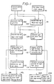
- Fig. 1 is a functional block diagram of one embodiment of the rear wheel steering apparatus according to the present ivnention;
- Fig. 2 schematically shows the arrangement of the embodiment;
- Fig. 3(A) is a partly-sectioned front view of a left rear wheel steer angle driving device;
- Fig. 3(B) is a sectional view taken along the line A-A of Fig. 3(A);
- Fig. 4 shows the operation of the embodiment; and
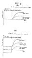
- Figs. 5(A) and 5(B) are graphs employed to explain advantages offered by the embodiment of the present invention.
- One embodiment of the rear wheel steering apparatus according to the present invention will be described hereinunder with reference to the accompanying drawings.
- Fig. 2 schematically shows the arrangement of one embodiment of the present invention. This embodiment will be explained below with reference to the functional block diagram shown in Fig. 1.
- A vehicle speed which is detected by a
vehicle speed sensor 10 is supplied to amicrocomputer 12, and a toe-in quantity is calculated in ablock 100. The toe-in quantity may be calculated according to the following formula:
T=k₁{a+tan⁻¹(bv+c)} ... (1) - In the formula (1), v represents a vehicle speed, and k₁, a, b and c are constants. According to the formula (1), T is an increasing function of v. It should be noted that, when v=0, T=0.
- An angle of rotation of a steering column shaft 14 (a front wheel steer angle ϑf) is detected by a front wheel
steer angle sensor 16 and supplied to themicrocomputer 12. The front wheelsteer angle sensor 16 is constituted by, for example, a rotary encoder or a potentiometer. In ablock 102, themicrocomputer 12 obtains a mean steer angle of the leftrear wheel 18L and the rightrear wheel 18R, i.e., a mean rear wheel steer angle ϑr, by the use of the detected front wheel steer angle ϑf and the detected vehicle speed v and in accordance with the following formula:
- In the formula (2), k₂, α and β are constants. According to the formula (2), ϑr is proportional to ϑf and is an increasing function of v. When v=0, the signs of ϑr and ϑf are opposite to each other, and when v²=α, ϑr is 0 regardless of the value of ϑf.
- Then, the
microcomputer 12 calculates a left rear wheel steer angle ϑrℓ and a right rear wheel steer angle ϑrr, which are target values, in accordance with the following formulae inblocks
ϑrℓ=ϑr+tan⁻¹ (T/2L) ... (3)
ϑrr=ϑr-tan⁻¹ (T/2L) ... (4) - In the above formulae, L represents the diameter of the rear wheels.
- As shown in Fig. 2, a
wheel supporting member 20L is rigidly secured to the leftrear wheel 18L. One end of afirst arm 22L is connected to the axial portion of thewheel supporting member 20L, and one end of asecond arm 24L is connected to a portion of themember 20L which is remote from the axial portion thereof. The other end of thesecond arm 24L, is connected to a left rear wheel steerangle driving device 26L, so that thesecond arm 24L is activated by thedriving device 26L to move horizontally as viewed in Fig. 2, thus enabling the leftrear wheel 18L to be pivoted. The left rear wheel steerangle driving device 26L is provided with a left rear wheelsteer angle sensor 28L to detect a steer angle of the leftrear wheel 18L, the detected steer a ngle being supplied to themicrocomputer 12. - The
microcomputer 12 makes, in ablock 108, comparison between the calculated left rear wheel steer angle ϑrℓ and an actual steer angle which is detected by the left rear wheelsteer angle sensor 28L, and calculates, in a block 110, a left rear wheel steer angle correction quantity which is proportional to the difference between the calculated steer angle and the detected actual steer angle. Themicrocomputer 12 then supplies a driving signal corresponding to the calculated correction quantity to the left rear wheel steerangle driving device 26L. In consequence, thesecond arm 24L is moved either leftward or rightward as viewed in Fig. 2, causing the leftrear wheel 18L to pivot so that the actual steer angle of the leftrear wheel 18L approaches the target value. - The arrangement of the right
rear wheel 18R and its associated elements is similar to that of the leftrear wheel 18L and its associated elements. Therefore, the same portions or members as those on the left rear wheel side are denoted by the same reference numerals, and R is suffixed thereto in place of L. Further, in Fig. 1, theblock 112 corresponds to theblock 108, and theblock 114 corresponds to the block 110. - The details of the left rear wheel steer
angle driving device 26L will be explained below with reference to Fig. 3. - A
worm 34 is fitted on a rotatingshaft 32 of amotor 30 and rigidly secured to theshaft 32 by apin 36. The distal end portion of the rotatingshaft 32 is rotatably supported by a radial bearing 40 which is rigidly secured to ahousing 38. Thehousing 38 is rigidly secured to avehicle body 46 through abracket 42 by means ofbolts 44. Theworm 34 is meshed with aworm wheel 48. Theworm wheel 48 is provided with aneccentric cam 50, a pillow ballinner tube 51 and aneccentric cam 54, which are laid one on top of another in that order. Ashaft 56 is passed through theworm wheel 48, thecam 50, theinner tube 51 and thecam 54, and these members are fastened together by means of anut 58. Theshaft 56 is eccentric with respect to the mutual center C of theworm wheel 48 and theeccentric cams outer tube 52 is fitted on the pillow ballinner tube 51, and thesecond arm 24L is welded to the peripheral surface of the pillow ballouter tube 52. Theeccentric cam 54 is rotatably supported by an angular contact ball bearing 60, and theeccentric cam 50 is rotatably supported by an anugular contact ball bearing 62. A bearing adjustnut 64 is in thread engagement with an opening provided at one end of thehousing 38, and acap 66 is fitted into an opening at the other end of thehousing 38. An O-ring 68 is provided on the inner peripheral surface of thehousing 38 so as to face the peripheral surface of thecap 66. - Accordingly, when the
motor 30 is turned on to rotate theworm 34, theworm wheel 48, theeccentric cam 50, the pillow ballinner tube 51 and theeccentric cam 54 rotate together in one unit around the mutual central axis C. In consequence, thesecond arm 24L is moved in the directions of the arrow X. The distal end portion of thesecond arm 24L is also movable vertically about the pillow ballinner tube 51, thereby allowing roll steer characteristics to be variable. - The amount of movement of the
second arm 24L is detected by a rear wheel steer angle detecting means. In this embodiment, the amount of movement of thesecond arm 24L is detected by the left rear wheelsteer angle sensor 28L which is rigidly secured to thehousing 38 in such a manner as to face the end face of theworm wheel 48. For example, the left rear wheelsteer angle sensor 28L is constituted by a combination of a light-emitting element and a light-receiving element, and a sheet of reflecting paper which is provided with reflecting regions at predetermined regular spacings is stuck to the end face of theworm wheel 48. In another example, magnets are buried in t he end face of theworm wheel 48 at predetermined regular spacings, and a change in impedance is detected by the left rear wheelsteer angle sensor 28L to detect an angle of rotation of theworm wheel 48, thereby detecting an amount of movement of thesecond arm 24L in the directions of the arrow X. - The arrangement of the right rear wheel steer
angle driving device 26R for the rightrear wheel 18R is the same as that of the above-described arrangement of the left rear wheel steerangle driving device 26L for the leftrear wheel 18L. - The operation of this embodiment, arranged as detailed above, will be explained below with reference to Fig. 4.
- When the vehicle is running straight at low speed, the front wheel steer angle ϑf is 0, and the means rear wheel steer angle ϑr is 0 from the formula (2). Since the value of v is relatively small, the toe-in quantity T is substantially 0 from the formula (1). Accordingly, both the left rear wheel steer angle ϑrℓ and the right rear wheel steer angle ϑrr are substantially 0 from the formulae (3) and (4).
- When the vehicle is running straight at high speed, ϑ f=0, and therefore ϑr=0 is found from the formula (2). It will be clear from the formula (1) that, as the value of v increases, the toe-in quantity T increases. Accordingly, the condition of ϑrℓ=-ϑrr holds from the formulae (3) and (4). As the vehicle speed increases, the toe-in quantity increases, and therefore it is possible to obtain straight running stability in correspondence with the vehicle speed.
- When the vehicle turns right while running at low speed, the toe-in quantity is substantially 0 from the formula (1). The means rear wheel steer angle ϑr is substantially proportional to the front wheel steer angle ϑf from the formula (2), the signs of ϑr and ϑf being opposite to each other. Accordingly, the condition of ϑrℓ=ϑrr holds from the formulae (3) and (4). The values of ϑrℓ and ϑrr at this time are proportional to the front wheel steer angle ϑf and opposite in sign to ϑf from the formulae (3) and (4). In consequence, the center of turning of the front wheels and that of the rear wheels are coincident with each other, so that the slip angle is decreased and the running stability is therefore improved.
- When the vehicle turns while running at high speed, the value of the toe-in quantity T increases as the value of v increases from the formula (1). The front wheel steer angle ϑr is substantially proportional to the mean rear wheel steer angle ϑf and the signs of these values are coincident with each other.
- When the vehicle turns at high speed after running straight at high speed, this embodiment offers the advantage as described below. Fig. 5(A) shows a case where the toe-in quantity T does not follow the formula (1), i.e., T=0. In such case, at the beginning of the high-speed turning, the cornering forces which act on the right and left rear wheels, respectively, increase gradually from zero, and the cornering force which acts on the whole of the rear wheels gradually increases with the passage of time. Accordingly, the response to a change in the angle of rotation of the steering wheel for turning the vehicle is unsatisfactory.
- In contrast to the above, according to this embodiment, the cornering force acring on the right rear wheel (the inner wheel) changes from a negative (away from the center of turning of the vehicle) value corresponding to a particular toe-in quantity to a positive (toward the center of turning) value. In this case, the cornering force which acts away from the center of turning quickly disappears. On the other hand, the cornering force which acts on the left rear wheel (the outer wheel) toward the center of turning increases so as to become larger than a positive value corresponding to the toe-in quantity. Accordingly, the cornering force which acts on the w hole of the rear wheels also suddenly changes, so that the response to a change in the angle of rotation of the steering wheel for turning the vehicle is improved.
- It should be noted that the rear wheel steer angle detecting means may be arranged such as to detect an amount of vertical movement of the second arm to correct a steer angle detected by each of the rear wheel
steer angle sensors - In the rear wheel steering apparatus according to the present invention, a toe-in quantity which is an increasing function of the vehicle speed is calculated by the use of a vehicle speed, while steer angles of the right and left rear wheels are calculated by the use of a vehicle speed and a front wheel steer angle, and the rear wheel steer angle driving means is controlled on the basis of results of these calculating operations such that the steer angle of each of the right and left rear wheels changes by a predetermined angle. Therefore, when the vehicle is tunning straight, it is possible to obtain an appropriate toe-in quantity in correspondece with the vehicle speed, so that the running stability is improved. At the beginning of a high-speed turning operation, a cornering force (the higher the vehicle speed, the larger the cornering force) toward the center of turning of the vehicle has already been acting on the outer rear wheel when the vehicle makes a turn, and the cornering force away from the center of turning which acts on the inner rear wheel disappears quickly (the higher the vehicle speed, the more quickly the cornering force disappears). Therefore, the cornering force which acts on the whole of the rear wheels rises sharply, and the response to a change in the angle of rotation of the steering wheel for turning the vehicle is improved, advantageously.
- Although the present invention has been described through specific terms, it should be noted here that the described embodiment is not necessarily limitative and various changes and modifications may be imparted thereto without departing from the scope of the invention which is limited solely by the appended claims.
Claims (9)
Applications Claiming Priority (2)
| Application Number | Priority Date | Filing Date | Title |
|---|---|---|---|
| JP60259470A JP2616762B2 (en) | 1985-11-19 | 1985-11-19 | Rear wheel steering device |
| JP259470/85 | 1985-11-19 |
Publications (3)
| Publication Number | Publication Date |
|---|---|
| EP0223256A2 true EP0223256A2 (en) | 1987-05-27 |
| EP0223256A3 EP0223256A3 (en) | 1988-03-30 |
| EP0223256B1 EP0223256B1 (en) | 1990-04-18 |
Family
ID=17334520
Family Applications (1)
| Application Number | Title | Priority Date | Filing Date |
|---|---|---|---|
| EP86116116A Expired EP0223256B1 (en) | 1985-11-19 | 1986-11-18 | Rear wheel steering apparatus for vehicle |
Country Status (4)
| Country | Link |
|---|---|
| US (1) | US4768603A (en) |
| EP (1) | EP0223256B1 (en) |
| JP (1) | JP2616762B2 (en) |
| DE (1) | DE3670468D1 (en) |
Cited By (8)
| Publication number | Priority date | Publication date | Assignee | Title |
|---|---|---|---|---|
| EP0249967A2 (en) * | 1986-06-20 | 1987-12-23 | Toyota Jidosha Kabushiki Kaisha | Apparatus for controlling a steering angle of a rear wheel |
| US4786066A (en) * | 1987-02-05 | 1988-11-22 | Mazda Motor Corporation | Rear wheels steering apparatus for vehicles |
| FR2620674A1 (en) * | 1987-07-29 | 1989-03-24 | Honda Motor Co Ltd | METHOD AND APPARATUS FOR CONTROLLING THE STEERING OPERATION OF A MOTOR VEHICLE WITH STEERING WHEELS |
| EP0439207A2 (en) * | 1990-01-25 | 1991-07-31 | General Motors Corporation | Rear wheel steering apparatus having toe error compensation |
| US5083627A (en) * | 1988-03-28 | 1992-01-28 | Honda Giken Kogyo Kabushiki Kaisha | Steering system for motor vehicle with steerable front and rear wheels |
| GB2272870A (en) * | 1992-07-07 | 1994-06-01 | Paulo Ferreira Silverio | "Road vehicle stabilizing device" |
| WO2015113536A1 (en) * | 2014-02-03 | 2015-08-06 | Schaeffler Technologies AG & Co. KG | Apparatus for toe and/or camber adjustment for a running gear of a motor vehicle |
| EP3254937A3 (en) * | 2016-06-09 | 2018-02-28 | Aisin Seiki Kabushiki Kaisha | Steering control apparatus |
Families Citing this family (20)
| Publication number | Priority date | Publication date | Assignee | Title |
|---|---|---|---|---|
| GB2188600B (en) * | 1986-04-07 | 1989-01-18 | Honda Motor Co Ltd | Steering system for front and rear wheels of automotive vehicle |
| JPS63287674A (en) * | 1987-05-19 | 1988-11-24 | Nissan Motor Co Ltd | Steering angle control device for vehicle |
| JPS6412974A (en) * | 1987-07-06 | 1989-01-17 | Mazda Motor | Rear wheel steering unit for vehicle |
| JP2534730B2 (en) * | 1987-09-29 | 1996-09-18 | 日産自動車株式会社 | 4-wheel steering / Differential limiting force integrated control device |
| JP2694554B2 (en) * | 1988-02-25 | 1997-12-24 | 富士重工業株式会社 | Rear wheel steering control method for automobiles |
| JP2742687B2 (en) * | 1988-02-25 | 1998-04-22 | 富士重工業株式会社 | Rear wheel steering control method for automobiles |
| JPH02241880A (en) * | 1989-03-16 | 1990-09-26 | Kayaba Ind Co Ltd | rear wheel steering device |
| US5143400A (en) * | 1989-08-10 | 1992-09-01 | Michelin Recherche Et Technique | Active toe adjustment apparatus |
| US5195601A (en) * | 1991-05-02 | 1993-03-23 | General Motors Corporation | Independent rear wheel toe-in control in a vehicle four wheel steering system |
| US5402341A (en) * | 1992-04-06 | 1995-03-28 | Ford Motor Company | Method and apparatus for four wheel steering control utilizing tire characteristics |
| KR950017622A (en) * | 1993-12-14 | 1995-07-20 | 전성원 | 4-wheel steering system |
| AUPM545594A0 (en) * | 1994-05-06 | 1994-05-26 | Spark, Ian James | Improved agricultural implement |
| DE102004053690A1 (en) * | 2004-11-06 | 2006-05-11 | Zf Lenksysteme Gmbh | Method and device for determining a steering angle of a vehicle |
| JP4448838B2 (en) * | 2006-08-25 | 2010-04-14 | 本田技研工業株式会社 | Vehicle toe angle variable control device |
| JP4920358B2 (en) * | 2006-09-19 | 2012-04-18 | 矢崎総業株式会社 | Terminal cover |
| JP5135224B2 (en) * | 2006-10-20 | 2013-02-06 | 本田技研工業株式会社 | Vehicle rear wheel rudder angle control device |
| EP2213547B1 (en) * | 2007-11-26 | 2011-12-21 | Honda Motor Co., Ltd. | Rear-wheel steering vehicle |
| JP5144304B2 (en) * | 2008-02-22 | 2013-02-13 | 本田技研工業株式会社 | Vehicle rear wheel steering device |
| SE536469C2 (en) * | 2012-04-24 | 2013-12-03 | Scania Cv Ab | Control system and method to reduce the effect of glitches on steering |
| US10259454B2 (en) * | 2016-11-16 | 2019-04-16 | Nio Usa, Inc. | System for controlling a vehicle based on wheel angle tracking |
Citations (3)
| Publication number | Priority date | Publication date | Assignee | Title |
|---|---|---|---|---|
| US4371191A (en) * | 1977-08-22 | 1983-02-01 | Springhill Laboratories, Inc. | Adjusting automobile suspension system |
| DE3300640A1 (en) * | 1983-01-11 | 1984-07-12 | Daimler-Benz Ag, 7000 Stuttgart | Supplementary steering for multi-axle vehicles, in particular passenger cars |
| GB2155869A (en) * | 1984-03-15 | 1985-10-02 | Honda Motor Co Ltd | Wheel alignment control system |
Family Cites Families (12)
| Publication number | Priority date | Publication date | Assignee | Title |
|---|---|---|---|---|
| JPS57192773A (en) * | 1981-05-25 | 1982-11-26 | Shin Nippon Kucho Kk | Air conditioner |
| JPS5830869A (en) * | 1981-08-12 | 1983-02-23 | Honda Motor Co Ltd | Steering gear for vehicle |
| JPS5830870A (en) * | 1981-08-12 | 1983-02-23 | Honda Motor Co Ltd | Steering gear for vehicle |
| JPS58214469A (en) * | 1982-06-07 | 1983-12-13 | Nissan Motor Co Ltd | Rear wheel steering device |
| JPS58214470A (en) * | 1982-06-07 | 1983-12-13 | Nissan Motor Co Ltd | Rear wheel steering device |
| JPS5923716A (en) * | 1982-07-31 | 1984-02-07 | Isuzu Motors Ltd | Controller for alignment of rear wheel |
| JPS59227565A (en) * | 1983-06-08 | 1984-12-20 | Mazda Motor Corp | Four wheel steering system |
| JPS6015051A (en) * | 1983-07-08 | 1985-01-25 | Nippon Kokan Kk <Nkk> | Continuous casting device of metallic plate |
| JPS60138815A (en) * | 1983-12-27 | 1985-07-23 | 株式会社信明産業 | Pressure switch and method of producing same |
| JPS60163714A (en) * | 1984-02-02 | 1985-08-26 | Mazda Motor Corp | Automobile rear suspension |
| JPS60169310A (en) * | 1984-02-15 | 1985-09-02 | Mazda Motor Corp | Rear suspension of car |
| JPS60193780A (en) * | 1984-03-15 | 1985-10-02 | Honda Motor Co Ltd | Toe varying apparatus for car |
-
1985
- 1985-11-19 JP JP60259470A patent/JP2616762B2/en not_active Expired - Lifetime
-
1986
- 1986-11-07 US US06/928,034 patent/US4768603A/en not_active Expired - Fee Related
- 1986-11-18 EP EP86116116A patent/EP0223256B1/en not_active Expired
- 1986-11-18 DE DE8686116116T patent/DE3670468D1/en not_active Expired - Lifetime
Patent Citations (3)
| Publication number | Priority date | Publication date | Assignee | Title |
|---|---|---|---|---|
| US4371191A (en) * | 1977-08-22 | 1983-02-01 | Springhill Laboratories, Inc. | Adjusting automobile suspension system |
| DE3300640A1 (en) * | 1983-01-11 | 1984-07-12 | Daimler-Benz Ag, 7000 Stuttgart | Supplementary steering for multi-axle vehicles, in particular passenger cars |
| GB2155869A (en) * | 1984-03-15 | 1985-10-02 | Honda Motor Co Ltd | Wheel alignment control system |
Cited By (15)
| Publication number | Priority date | Publication date | Assignee | Title |
|---|---|---|---|---|
| EP0249967A3 (en) * | 1986-06-20 | 1989-03-08 | Toyota Jidosha Kabushiki Kaisha | Apparatus for controlling a steering angle of a rear wheel |
| EP0249967A2 (en) * | 1986-06-20 | 1987-12-23 | Toyota Jidosha Kabushiki Kaisha | Apparatus for controlling a steering angle of a rear wheel |
| US4786066A (en) * | 1987-02-05 | 1988-11-22 | Mazda Motor Corporation | Rear wheels steering apparatus for vehicles |
| FR2620674A1 (en) * | 1987-07-29 | 1989-03-24 | Honda Motor Co Ltd | METHOD AND APPARATUS FOR CONTROLLING THE STEERING OPERATION OF A MOTOR VEHICLE WITH STEERING WHEELS |
| GB2208375A (en) * | 1987-07-29 | 1989-03-30 | Honda Motor Co Ltd | Four wheel steering system |
| US4939653A (en) * | 1987-07-29 | 1990-07-03 | Honda Giken Kogyo Kabushiki Kaisha | Method of and apparatus for controlling steering operation of a motor vehicle with steerable front and rear wheels |
| GB2208375B (en) * | 1987-07-29 | 1991-08-14 | Honda Motor Co Ltd | Method of and apparatus for controlling steering operation of a motor vehicle with steerable front and rear wheels |
| US5083627A (en) * | 1988-03-28 | 1992-01-28 | Honda Giken Kogyo Kabushiki Kaisha | Steering system for motor vehicle with steerable front and rear wheels |
| EP0439207A2 (en) * | 1990-01-25 | 1991-07-31 | General Motors Corporation | Rear wheel steering apparatus having toe error compensation |
| EP0439207A3 (en) * | 1990-01-25 | 1992-04-01 | General Motors Corporation | Rear wheel steering apparatus having toe error compensation |
| GB2272870A (en) * | 1992-07-07 | 1994-06-01 | Paulo Ferreira Silverio | "Road vehicle stabilizing device" |
| GB2272870B (en) * | 1992-07-07 | 1996-06-12 | Paulo Ferreira Silverio | Road vehicle stabilizing device |
| WO2015113536A1 (en) * | 2014-02-03 | 2015-08-06 | Schaeffler Technologies AG & Co. KG | Apparatus for toe and/or camber adjustment for a running gear of a motor vehicle |
| US10214065B2 (en) | 2014-02-03 | 2019-02-26 | Schaeffler Technologies AG & Co. KG | Apparatus for toe and/or camber adjustment for a running gear of a motor vehicle |
| EP3254937A3 (en) * | 2016-06-09 | 2018-02-28 | Aisin Seiki Kabushiki Kaisha | Steering control apparatus |
Also Published As
| Publication number | Publication date |
|---|---|
| JP2616762B2 (en) | 1997-06-04 |
| US4768603A (en) | 1988-09-06 |
| DE3670468D1 (en) | 1990-05-23 |
| EP0223256B1 (en) | 1990-04-18 |
| JPS62120274A (en) | 1987-06-01 |
| EP0223256A3 (en) | 1988-03-30 |
Similar Documents
| Publication | Publication Date | Title |
|---|---|---|
| EP0223256A2 (en) | Rear wheel steering apparatus for vehicle | |
| EP0221547B1 (en) | Steer angle adjusting apparatus for vehicle | |
| US4811969A (en) | Apparatus for controlling a steering angle of a rear wheel | |
| CN102105342A (en) | Vehicular steering apparatus and control method thereof | |
| US5365440A (en) | Four wheel steering system | |
| EP1232930A2 (en) | Oversteer control for a motor vehicle | |
| EP0209117B1 (en) | Vehicle steering system | |
| US5189616A (en) | Four-wheel steering system for motor vehicle | |
| US5225753A (en) | Electric control apparatus for four-wheel steering system | |
| KR100589135B1 (en) | Vehicle wheel alignment automatic adjustment device | |
| JP2957603B2 (en) | Front wheel steering angle correction device | |
| JPS60185674A (en) | Four-wheel steering unit for vehicle | |
| JP2594816B2 (en) | Automobile four-wheel steering device and four-wheel steering method | |
| JP2594815B2 (en) | Automobile four-wheel steering method | |
| JP2870844B2 (en) | Rear wheel steering device | |
| JPS6218368A (en) | Four-wheel steering gear for vehicle | |
| JPH1159358A (en) | Determination device for tire of different diameter | |
| JPS62146777A (en) | Four-wheel steering device for vehicle | |
| JPH0490972A (en) | Control device for front and rear wheel steering vehicle | |
| JPH02256564A (en) | Rear wheel steering device for vehicle | |
| JPH03193558A (en) | Rear-wheel steering controller for all-wheel steering vehicle | |
| JPH03243469A (en) | Control device for front and rear wheel steering vehicle | |
| JPH0519062U (en) | Control device for front and rear wheel steering vehicle | |
| JPS63112284A (en) | Four-wheel steering device for vehicle | |
| JPH0557949B2 (en) |
Legal Events
| Date | Code | Title | Description |
|---|---|---|---|
| PUAI | Public reference made under article 153(3) epc to a published international application that has entered the european phase |
Free format text: ORIGINAL CODE: 0009012 |
|
| AK | Designated contracting states |
Kind code of ref document: A2 Designated state(s): DE FR GB |
|
| PUAL | Search report despatched |
Free format text: ORIGINAL CODE: 0009013 |
|
| AK | Designated contracting states |
Kind code of ref document: A3 Designated state(s): DE FR GB |
|
| 17P | Request for examination filed |
Effective date: 19880502 |
|
| 17Q | First examination report despatched |
Effective date: 19880902 |
|
| GRAA | (expected) grant |
Free format text: ORIGINAL CODE: 0009210 |
|
| RAP1 | Party data changed (applicant data changed or rights of an application transferred) |
Owner name: TOYOTA JIDOSHA KABUSHIKI KAISHA |
|
| AK | Designated contracting states |
Kind code of ref document: B1 Designated state(s): DE FR GB |
|
| REF | Corresponds to: |
Ref document number: 3670468 Country of ref document: DE Date of ref document: 19900523 |
|
| ET | Fr: translation filed | ||
| PLBE | No opposition filed within time limit |
Free format text: ORIGINAL CODE: 0009261 |
|
| STAA | Information on the status of an ep patent application or granted ep patent |
Free format text: STATUS: NO OPPOSITION FILED WITHIN TIME LIMIT |
|
| 26N | No opposition filed | ||
| PGFP | Annual fee paid to national office [announced via postgrant information from national office to epo] |
Ref country code: GB Payment date: 19961111 Year of fee payment: 11 Ref country code: FR Payment date: 19961111 Year of fee payment: 11 |
|
| PGFP | Annual fee paid to national office [announced via postgrant information from national office to epo] |
Ref country code: DE Payment date: 19961122 Year of fee payment: 11 |
|
| PG25 | Lapsed in a contracting state [announced via postgrant information from national office to epo] |
Ref country code: GB Free format text: LAPSE BECAUSE OF NON-PAYMENT OF DUE FEES Effective date: 19971118 |
|
| PG25 | Lapsed in a contracting state [announced via postgrant information from national office to epo] |
Ref country code: FR Free format text: THE PATENT HAS BEEN ANNULLED BY A DECISION OF A NATIONAL AUTHORITY Effective date: 19971130 |
|
| GBPC | Gb: european patent ceased through non-payment of renewal fee |
Effective date: 19971118 |
|
| PG25 | Lapsed in a contracting state [announced via postgrant information from national office to epo] |
Ref country code: DE Free format text: LAPSE BECAUSE OF NON-PAYMENT OF DUE FEES Effective date: 19980801 |
|
| REG | Reference to a national code |
Ref country code: FR Ref legal event code: ST |