EP0223214A1 - XY table - Google Patents
XY table Download PDFInfo
- Publication number
- EP0223214A1 EP0223214A1 EP86115851A EP86115851A EP0223214A1 EP 0223214 A1 EP0223214 A1 EP 0223214A1 EP 86115851 A EP86115851 A EP 86115851A EP 86115851 A EP86115851 A EP 86115851A EP 0223214 A1 EP0223214 A1 EP 0223214A1
- Authority
- EP
- European Patent Office
- Prior art keywords
- rail
- servomotor
- frame
- moving means
- moving
- Prior art date
- Legal status (The legal status is an assumption and is not a legal conclusion. Google has not performed a legal analysis and makes no representation as to the accuracy of the status listed.)
- Granted
Links
- 238000005520 cutting process Methods 0.000 claims abstract description 8
- 238000003754 machining Methods 0.000 claims abstract description 4
- XEEYBQQBJWHFJM-UHFFFAOYSA-N Iron Chemical compound [Fe] XEEYBQQBJWHFJM-UHFFFAOYSA-N 0.000 abstract description 18
- 229910052742 iron Inorganic materials 0.000 abstract description 9
- 238000010586 diagram Methods 0.000 description 1
- 238000000034 method Methods 0.000 description 1
Images
Classifications
-
- B—PERFORMING OPERATIONS; TRANSPORTING
- B25—HAND TOOLS; PORTABLE POWER-DRIVEN TOOLS; MANIPULATORS
- B25H—WORKSHOP EQUIPMENT, e.g. FOR MARKING-OUT WORK; STORAGE MEANS FOR WORKSHOPS
- B25H7/00—Marking-out or setting-out work
-
- B—PERFORMING OPERATIONS; TRANSPORTING
- B23—MACHINE TOOLS; METAL-WORKING NOT OTHERWISE PROVIDED FOR
- B23Q—DETAILS, COMPONENTS, OR ACCESSORIES FOR MACHINE TOOLS, e.g. ARRANGEMENTS FOR COPYING OR CONTROLLING; MACHINE TOOLS IN GENERAL CHARACTERISED BY THE CONSTRUCTION OF PARTICULAR DETAILS OR COMPONENTS; COMBINATIONS OR ASSOCIATIONS OF METAL-WORKING MACHINES, NOT DIRECTED TO A PARTICULAR RESULT
- B23Q9/00—Arrangements for supporting or guiding portable metal-working machines or apparatus
- B23Q9/0014—Portable machines provided with or cooperating with guide means supported directly by the workpiece during action
-
- B—PERFORMING OPERATIONS; TRANSPORTING
- B23—MACHINE TOOLS; METAL-WORKING NOT OTHERWISE PROVIDED FOR
- B23Q—DETAILS, COMPONENTS, OR ACCESSORIES FOR MACHINE TOOLS, e.g. ARRANGEMENTS FOR COPYING OR CONTROLLING; MACHINE TOOLS IN GENERAL CHARACTERISED BY THE CONSTRUCTION OF PARTICULAR DETAILS OR COMPONENTS; COMBINATIONS OR ASSOCIATIONS OF METAL-WORKING MACHINES, NOT DIRECTED TO A PARTICULAR RESULT
- B23Q1/00—Members which are comprised in the general build-up of a form of machine, particularly relatively large fixed members
- B23Q1/25—Movable or adjustable work or tool supports
- B23Q1/44—Movable or adjustable work or tool supports using particular mechanisms
- B23Q1/56—Movable or adjustable work or tool supports using particular mechanisms with sliding pairs only, the sliding pairs being the first two elements of the mechanism
- B23Q1/60—Movable or adjustable work or tool supports using particular mechanisms with sliding pairs only, the sliding pairs being the first two elements of the mechanism two sliding pairs only, the sliding pairs being the first two elements of the mechanism
- B23Q1/62—Movable or adjustable work or tool supports using particular mechanisms with sliding pairs only, the sliding pairs being the first two elements of the mechanism two sliding pairs only, the sliding pairs being the first two elements of the mechanism with perpendicular axes, e.g. cross-slides
- B23Q1/621—Movable or adjustable work or tool supports using particular mechanisms with sliding pairs only, the sliding pairs being the first two elements of the mechanism two sliding pairs only, the sliding pairs being the first two elements of the mechanism with perpendicular axes, e.g. cross-slides a single sliding pair followed perpendicularly by a single sliding pair
-
- B—PERFORMING OPERATIONS; TRANSPORTING
- B44—DECORATIVE ARTS
- B44B—MACHINES, APPARATUS OR TOOLS FOR ARTISTIC WORK, e.g. FOR SCULPTURING, GUILLOCHING, CARVING, BRANDING, INLAYING
- B44B3/00—Artist's machines or apparatus equipped with tools or work holders moving or able to be controlled substantially two- dimensionally for carving, engraving, or guilloching shallow ornamenting or markings
- B44B3/009—Artist's machines or apparatus equipped with tools or work holders moving or able to be controlled substantially two- dimensionally for carving, engraving, or guilloching shallow ornamenting or markings using a computer control means
-
- B—PERFORMING OPERATIONS; TRANSPORTING
- B44—DECORATIVE ARTS
- B44B—MACHINES, APPARATUS OR TOOLS FOR ARTISTIC WORK, e.g. FOR SCULPTURING, GUILLOCHING, CARVING, BRANDING, INLAYING
- B44B3/00—Artist's machines or apparatus equipped with tools or work holders moving or able to be controlled substantially two- dimensionally for carving, engraving, or guilloching shallow ornamenting or markings
- B44B3/02—Artist's machines or apparatus equipped with tools or work holders moving or able to be controlled substantially two- dimensionally for carving, engraving, or guilloching shallow ornamenting or markings wherein plane surfaces are worked
-
- B—PERFORMING OPERATIONS; TRANSPORTING
- B44—DECORATIVE ARTS
- B44B—MACHINES, APPARATUS OR TOOLS FOR ARTISTIC WORK, e.g. FOR SCULPTURING, GUILLOCHING, CARVING, BRANDING, INLAYING
- B44B3/00—Artist's machines or apparatus equipped with tools or work holders moving or able to be controlled substantially two- dimensionally for carving, engraving, or guilloching shallow ornamenting or markings
- B44B3/06—Accessories, e.g. tool or work holders
- B44B3/061—Tool heads
Definitions
- This invention relates to an improved XY table.
- a plate or the like is cut along an imaginary line or a marked line. For example, if a thick iron plate is cut by a gas toach or plasma toach.
- the cutting operation may be manual or automatic.
- the object of this invention is to provide a XY table which can be easily moved to a desired position for various operations.
- a XY table for processing an object such as an iron plate comprising a frame having an opening formed thereby, a moving means moving in a X direction and in a Y direction at a right angle to the X direction, a head for cutting, marking or machining attached to the moving means for processing the object through the opening, and setting means for setting detachably the frame to the object.
- a XY table l has a frame 2 which comprises a pair of opposite side member 3, 4, a rail member 5 and a connection member 6. An opening is formed by the members 3, 4, 5, 6.
- a groove 8 is formed in the longitudinal direction of the rail member 5.
- a rail ll is set on the members 3, 4, 6. This rail ll is in parallel to the rail member 5.
- the side members 3, 4 are in parallel to each other.
- a movable rail l2 is set between the rail member 5 and the rail ll in such a way that the movable rail l2 is at a right angle to the rail member 5 and the rail ll.
- a projection l3 fixed to one end of the movable rail l2 is slidably set in the groove 8 of the rail member 5.
- the other end of the movable rail l2 is equipped with a nut l4.
- a male screw member l5 extends in the longitudinal direction of the rail ll.
- One end of the male screw member l5 is joined to an output shaft of a servomotor 9.
- the other end of the screw member l5 is supported by a bearing l7.
- the nut l4 engages the male screw member l5.
- the nut l4 and the male screw member l5 can constitute a conventional ball screw.
- the male screw member l5 is driven by a servomotor 9.
- the nut l4 moves along the screw member l5 in the direction of arrow X.
- the movable rail l2 can move along the rail member 5 and the rail ll in the direction of arrow X.
- a screw shaft l6 extends in the longitudinal direction of the movable rail l2. One end of this screw shaft l6 is joined to an output shaft of a servomotor l0. The other end of the screw shaft l6 is supported by a bearing l8. The screw shaft l6 is rotated by the servomotor l0. The screw shaft l6 engages a nut l9 so as to constitute a ball screw. The nut l6 is attached to a moving means 20. In response to rotation of the servomotor l0, the moving means 20 can move in the direction of arrow Y at a right angle to the direction of arrow X.
- a working head 2l may be a head for a plasma cutting toach, a machining tool, marking-off means and any other processing means.
- the head 2l is set in the moving means 20 in such a way that the head 2l can process an object 22 such as an iron plate or the like.
- the setting means 23 are attached to a bottom portion of the frame 2 at its four corners.
- the setting means 23 are used to set detachably the frame 2 to the object 22.
- the object 22 is an iron plate
- the setting means 23 can be formed of a magnet.
- the setting means 23 can be formed of a suction type.
- a U-shaped handgrip 24 is fixed to the side member 3 while a U-shaped handgrip 25 is fixed to the side member 4, so that the XY table can be easily handled if an operator grips the handgrips 24, 25.
- NC programs in a NC tape 76 is read by a tape reader 77 so as to send an input signal to a CPU 67.
- the servo means 68 for controlling the servomotor 9 is actuated in response to a signal sent from the CPU 67.
- the servo means 69 for controlling the servomotor l0 is actuated in response to a signal from the CPU 67.
- the servo means 68, 69 may be conventional ones. Therefore, only the servo means 68 will be briefly explained.
- Elements 72 to 75 and 80 to 82 in the servo means 68 correspond to elements l72 to l75 and l80 to l82 in the servo means 69, respectively.
- a position control means 72 includes a pulse shaping-direction decision circuit 73, a deviation counter 74 and a D-A converter 75.
- the CPU 67 sends a moving command pulse or pulses 72a and a command signal or signals 72b for controlling a rotation direction of the servomotor 9.
- An output portion of the position control means 72 is connected to a speed control means 80 which is connected to the servomotor 9.
- An output shaft of the servomotor 9 is joined to a tachogenerator 8l and a pulse generator 82.
- the tachogenerator 8l is used to detect a rotation speed of the servomotor 9.
- the output voltage of the tachogenerator 8l is in proportion to the rotation speed thereof.
- the polarity of the output voltage depends on the rotation direction of the servomotor 9.
- the pulse generator 82 is used to detect a rotation angle of the servomotor 9.
- the number of the pulses produced by the pulse generator 82 is in proportion to the rotation angle thereof.
- the polarity of the output pulse depends on the rotation direction of the servomotor 9.
- the tachogenerator 8l is connected to the speed control means 80.
- the pulse generator 82 is connected to the pulse shaping-direction decision circuit 73.
- the deviation counter 74 produces an output signal which is an output voltage equal to a difference between the number of the moving command pulses 72a and the number of the moving feed-back pulses fed back from the pulse generator 82.
- the output voltage is in proportion to the above-stated difference, and the polarity of the output voltage depends on the polarity of the above-stated difference.
- the output voltage is digital, after converted at the D-A converter 75, it is sent to the speed control means 80 as a speed command voltage.
- the speed control means 80 compares the speed feed back voltage sent from the tachogenerator 8l with the speed command voltage. After a difference between those voltages is amplified, the speed of the servomotor 9 is controlled until the voltage difference therebetween becomes substantially zero.
- the moving command pulse or pulses 72a are sent by way of the pulse shaping-direction decision circuit 73 to the deviation counter 74, and then the number of the the pulses is counted by the counter 74.
- This counted pulse number is converted into the speed command voltage by the D-A converter 75 and thereafter sent to the speed control means 80.
- the servomotor 9 begins to rotate.
- the pulse generator 82 produces a number of pulses in proportion to the rotation angle of the servomotor 9. Those pulses are counted by the deviation counter 74. The number of the counted pulses in the deviation counter 74 is substracted.
- the servomotor 9 continues to rotate, and the deviation counter 74 holds a predetermined number of counted pulses.
- the rotation speed of the servomotor 9 is in proportion to the frequency of the moving command pulses 72a.
- the servomotor 9 rotates only until the counted pulses in the deviation counter 74 become zero.
- the servomotor l0 in the servo means 69 is controlled in the same manner as the aervomotor 9.
- an operator holds the hand grips 24, 25 and moves the XY table l onto the object 22 such as a thick iron plate.
- the working head 2l is attached to the moving means 20. A tip portion of the working head 2l is set near the object 22. If a start button (not shown) is pushed, the NC tape 76 is read by the reader 77 thereby to control the servomotors 9, l0.
- the moving means 20 and the head 2l move in both directions of arrows X and Y along a predetermined moving course 26 whereby the object 22 can be cut in a desired shape. After the cutting operation is finished, the operator again holds the hand grips 24, 25 and moves the XY table l from the object 22 to a desired place.
- the XY table can be made in a very compact size. Therefore, it is easy to move the XY table to a desired position for various operations such as cutting or marking. Accordingly, even if a very large object such as a heavy iron plate is to be processed, a XY table according to this invention can be easily moved to the object. It should be noted that the object need not be moved.
- the XY table l can be forcedly set in a desired positon on the object 22 even if the object 22 is inclined or vertically positioned.
- the working head 2l can be of any type including a toach head, a marking head, and a tool head.
- the tool head is a drill or an end mill.
- a linear pulse motor can be used in place of a ball screw.
Landscapes
- Engineering & Computer Science (AREA)
- Mechanical Engineering (AREA)
- General Engineering & Computer Science (AREA)
- Machine Tool Units (AREA)
- Arc Welding In General (AREA)
Abstract
Description
- This invention relates to an improved XY table.
- A plate or the like is cut along an imaginary line or a marked line. For example, if a thick iron plate is cut by a gas toach or plasma toach. The cutting operation may be manual or automatic.
- It is not easy to handle a heavy iron plate. Also, a large iron plate can not be easily cut by a reasonable size of cutting machine.
- The object of this invention is to provide a XY table which can be easily moved to a desired position for various operations.
- According to this invention, there is provided a XY table for processing an object such as an iron plate comprising a frame having an opening formed thereby, a moving means moving in a X direction and in a Y direction at a right angle to the X direction, a head for cutting, marking or machining attached to the moving means for processing the object through the opening, and setting means for setting detachably the frame to the object.
-
- Fig. l is a front view showing a XY table according to a preferred embodiment of this invention;
- Fig. 2 is a side view showing XY table shown in Fig. l;
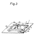
- Fig. 3 is a perspective view showing the XY table shown in Fig. l; and
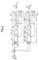
- Fig. 4 is a block diagram showing a control system for servomotors for use in the XY Table shown in Fig. l.
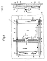
- Referring to Figs. l through 3, a XY table l has a
frame 2 which comprises a pair ofopposite side member rail member 5 and a connection member 6. An opening is formed by themembers - A
groove 8 is formed in the longitudinal direction of therail member 5. A rail ll is set on themembers rail member 5. Theside members - A movable rail l2 is set between the
rail member 5 and the rail ll in such a way that the movable rail l2 is at a right angle to therail member 5 and the rail ll. A projection l3 fixed to one end of the movable rail l2 is slidably set in thegroove 8 of therail member 5. The other end of the movable rail l2 is equipped with a nut l4. - A male screw member l5 extends in the longitudinal direction of the rail ll. One end of the male screw member l5 is joined to an output shaft of a
servomotor 9. The other end of the screw member l5 is supported by a bearing l7. The nut l4 engages the male screw member l5. The nut l4 and the male screw member l5 can constitute a conventional ball screw. - The male screw member l5 is driven by a
servomotor 9. In response to rotation of the male screw member l5, the nut l4 moves along the screw member l5 in the direction of arrow X. The movable rail l2 can move along therail member 5 and the rail ll in the direction of arrow X. - A screw shaft l6 extends in the longitudinal direction of the movable rail l2. One end of this screw shaft l6 is joined to an output shaft of a servomotor l0. The other end of the screw shaft l6 is supported by a bearing l8. The screw shaft l6 is rotated by the servomotor l0. The screw shaft l6 engages a nut l9 so as to constitute a ball screw. The nut l6 is attached to a moving means 20. In response to rotation of the servomotor l0, the moving
means 20 can move in the direction of arrow Y at a right angle to the direction of arrow X. - A working head 2l may be a head for a plasma cutting toach, a machining tool, marking-off means and any other processing means. The head 2l is set in the moving means 20 in such a way that the head 2l can process an
object 22 such as an iron plate or the like. - Four setting means 23 are attached to a bottom portion of the
frame 2 at its four corners. The setting means 23 are used to set detachably theframe 2 to theobject 22. For example, if theobject 22 is an iron plate, the setting means 23 can be formed of a magnet. Also, the setting means 23 can be formed of a suction type. - A U-shaped
handgrip 24 is fixed to theside member 3 while aU-shaped handgrip 25 is fixed to theside member 4, so that the XY table can be easily handled if an operator grips thehandgrips - Referring now to Fig. 4, a control system for the
servomotors 9, l0 will be explained. - NC programs in a
NC tape 76 is read by a tape reader 77 so as to send an input signal to aCPU 67. The servo means 68 for controlling theservomotor 9 is actuated in response to a signal sent from theCPU 67. The servo means 69 for controlling the servomotor l0 is actuated in response to a signal from theCPU 67. The servo means 68, 69 may be conventional ones. Therefore, only the servo means 68 will be briefly explained.Elements 72 to 75 and 80 to 82 in the servo means 68 correspond to elements l72 to l75 and l80 to l82 in the servo means 69, respectively. - A position control means 72 includes a pulse shaping-
direction decision circuit 73, adeviation counter 74 and aD-A converter 75. TheCPU 67 sends a moving command pulse or pulses 72a and a command signal or signals 72b for controlling a rotation direction of theservomotor 9. An output portion of the position control means 72 is connected to a speed control means 80 which is connected to theservomotor 9. An output shaft of theservomotor 9 is joined to a tachogenerator 8l and apulse generator 82. The tachogenerator 8l is used to detect a rotation speed of theservomotor 9. The output voltage of the tachogenerator 8l is in proportion to the rotation speed thereof. The polarity of the output voltage depends on the rotation direction of theservomotor 9. Thepulse generator 82 is used to detect a rotation angle of theservomotor 9. The number of the pulses produced by thepulse generator 82 is in proportion to the rotation angle thereof. The polarity of the output pulse depends on the rotation direction of theservomotor 9. - The tachogenerator 8l is connected to the speed control means 80. The
pulse generator 82 is connected to the pulse shaping-direction decision circuit 73. - The
deviation counter 74 produces an output signal which is an output voltage equal to a difference between the number of the moving command pulses 72a and the number of the moving feed-back pulses fed back from thepulse generator 82. The output voltage is in proportion to the above-stated difference, and the polarity of the output voltage depends on the polarity of the above-stated difference. - As the output voltage is digital, after converted at the
D-A converter 75, it is sent to the speed control means 80 as a speed command voltage. The speed control means 80 compares the speed feed back voltage sent from the tachogenerator 8l with the speed command voltage. After a difference between those voltages is amplified, the speed of theservomotor 9 is controlled until the voltage difference therebetween becomes substantially zero. - When the
servomotor 9 starts, the moving command pulse or pulses 72a are sent by way of the pulse shaping-direction decision circuit 73 to thedeviation counter 74, and then the number of the the pulses is counted by thecounter 74. This counted pulse number is converted into the speed command voltage by theD-A converter 75 and thereafter sent to the speed control means 80. As a result, theservomotor 9 begins to rotate. In response to rotation of theservomotor 9, thepulse generator 82 produces a number of pulses in proportion to the rotation angle of theservomotor 9. Those pulses are counted by thedeviation counter 74. The number of the counted pulses in thedeviation counter 74 is substracted. If the moving command pulses 72a are continuously sent thereto, theservomotor 9 continues to rotate, and thedeviation counter 74 holds a predetermined number of counted pulses. The rotation speed of theservomotor 9 is in proportion to the frequency of the moving command pulses 72a. - If input of the moving command pulse 72a stops, the
servomotor 9 rotates only until the counted pulses in thedeviation counter 74 become zero. - The servomotor l0 in the servo means 69 is controlled in the same manner as the
aervomotor 9. - In operation, an operator holds the hand grips 24, 25 and moves the XY table l onto the
object 22 such as a thick iron plate. The working head 2l is attached to the movingmeans 20. A tip portion of the working head 2l is set near theobject 22. If a start button (not shown) is pushed, theNC tape 76 is read by the reader 77 thereby to control theservomotors 9, l0. The moving means 20 and the head 2l move in both directions of arrows X and Y along a predetermined moving course 26 whereby theobject 22 can be cut in a desired shape. After the cutting operation is finished, the operator again holds the hand grips 24, 25 and moves the XY table l from theobject 22 to a desired place. - According to this invention, the XY table can be made in a very compact size. Therefore, it is easy to move the XY table to a desired position for various operations such as cutting or marking. Accordingly, even if a very large object such as a heavy iron plate is to be processed, a XY table according to this invention can be easily moved to the object. It should be noted that the object need not be moved.
- If the setting means 23 is of a magnet type or a suction type, the XY table l can be forcedly set in a desired positon on the
object 22 even if theobject 22 is inclined or vertically positioned. - This invention is not limited to the above-mentioned embodiment only. For example, the working head 2l can be of any type including a toach head, a marking head, and a tool head. Examples of the tool head is a drill or an end mill. Also, a linear pulse motor can be used in place of a ball screw.
Claims (5)
a moving means (20) which moves in a X-direction and in a Y-direction at a right angle to the X-direction;
means (67, 68, 69, 76, 77) for controlling movement of the moving means (20);
a head (2l) for cutting, marking or machining set to the moving means (20) for processing an object (22) through the opening; and
setting means (23) attached to the frame (2) for setting detachably the frame (2) to the object (22).
Applications Claiming Priority (2)
| Application Number | Priority Date | Filing Date | Title |
|---|---|---|---|
| JP258786/85 | 1985-11-20 | ||
| JP60258786A JPS62120928A (en) | 1985-11-20 | 1985-11-20 | Xy table |
Publications (2)
| Publication Number | Publication Date |
|---|---|
| EP0223214A1 true EP0223214A1 (en) | 1987-05-27 |
| EP0223214B1 EP0223214B1 (en) | 1990-01-10 |
Family
ID=17325051
Family Applications (1)
| Application Number | Title | Priority Date | Filing Date |
|---|---|---|---|
| EP86115851A Expired - Lifetime EP0223214B1 (en) | 1985-11-20 | 1986-11-14 | Xy table |
Country Status (6)
| Country | Link |
|---|---|
| US (1) | US4713887A (en) |
| EP (1) | EP0223214B1 (en) |
| JP (1) | JPS62120928A (en) |
| KR (1) | KR920000022B1 (en) |
| CA (1) | CA1263523A (en) |
| DE (1) | DE3668129D1 (en) |
Cited By (3)
| Publication number | Priority date | Publication date | Assignee | Title |
|---|---|---|---|---|
| EP0371896A1 (en) * | 1988-12-01 | 1990-06-06 | TECHNIFOR Société Anonyme | Device for marking by micro-percussion |
| EP0472979A1 (en) * | 1990-08-28 | 1992-03-04 | Alfred Beer | Machine-tool for working plate like workpieces |
| US20180050430A1 (en) * | 2016-08-22 | 2018-02-22 | Henry Ashworth | Portable rail system for mounting an engraving device |
Families Citing this family (18)
| Publication number | Priority date | Publication date | Assignee | Title |
|---|---|---|---|---|
| US4876789A (en) * | 1988-04-22 | 1989-10-31 | Burwell Joseph M | Apparatus for measuring and cutting sheetrock |
| USD310639S (en) | 1988-05-17 | 1990-09-18 | Gerber Garment Technology, Inc. | X, Y plotter |
| WO1992013443A1 (en) * | 1991-02-01 | 1992-08-20 | Plant Production Systems B.V. | A method for use in a multiplication process of plants and a device for carrying out said method |
| US5316397A (en) * | 1992-07-31 | 1994-05-31 | Telesis Marking Systems, Inc. | Marking apparatus with multiple marking modes |
| US5327653A (en) * | 1992-08-19 | 1994-07-12 | Pistorius Robert T | Miter linear measurement gage |
| US5523941A (en) * | 1994-10-04 | 1996-06-04 | Burton; Gary L. | X-Y-theta positioning mechanism |
| ES2163946B2 (en) * | 1998-05-28 | 2002-11-16 | Proyectos Y Fabricacion Electr | MARKER WITH FIXED ENGINES. |
| AU2004201410B2 (en) * | 2003-04-02 | 2005-11-24 | Bluescope Steel Limited | Production of cladding sheets |
| US7772947B2 (en) * | 2003-10-31 | 2010-08-10 | Massachusetts Institute Of Technology | Variable reluctance fast positioning system and methods |
| FR2924960B1 (en) * | 2007-12-12 | 2010-04-30 | Electricite De France | MILLING MACHINE. |
| CA2625566C (en) * | 2008-04-14 | 2011-06-14 | Anna Stoklosa | Tool, method and marking system |
| CN102554638B (en) * | 2010-12-31 | 2016-06-29 | 富泰华工业(深圳)有限公司 | Positioning machine table |
| US9460634B2 (en) * | 2011-05-02 | 2016-10-04 | University Of Vermont And State Agricultural College | Systems for and methods of digital recording and reproduction of tactile drawings |
| CA2839224C (en) * | 2014-01-16 | 2020-03-31 | Anna A. S. Stoklosa | Mechanism for tool, method and marking system |
| US10367403B2 (en) | 2014-08-21 | 2019-07-30 | General Electric Company | Systems and methods for independent motion of parallel actuators |
| US10877459B2 (en) * | 2016-05-04 | 2020-12-29 | Yelizaveta Kholodkova | Apparatus for outlining on vertical surface and methods of use |
| US10369689B2 (en) * | 2017-03-24 | 2019-08-06 | McKay Ballard | Adjustable universal hardware installation and machining jig for carpentry application |
| CA3092177A1 (en) * | 2020-01-29 | 2021-07-29 | Lianna Genovese | Devices and methods for assisting a user to manipulate an instrument |
Citations (4)
| Publication number | Priority date | Publication date | Assignee | Title |
|---|---|---|---|---|
| GB551514A (en) * | 1942-09-30 | 1943-02-25 | Samuel Griffiths Willenhall Lt | Improvements in metal-milling machines |
| GB1001777A (en) * | 1963-07-30 | 1965-08-18 | Hugh Smith Glasgow Ltd | Portable milling machine |
| CH417043A (en) * | 1964-04-03 | 1966-07-15 | Fischer Ag Brugg Georg | Control for router for automatic execution of a machining cycle |
| DE2552742A1 (en) * | 1975-11-25 | 1977-05-26 | Masch Und Formenbau Gmbh | Large workpiece machining unit - incorporates magnet system on which adjustable longitudinal, transverse and vertical support is fitted |
Family Cites Families (10)
| Publication number | Priority date | Publication date | Assignee | Title |
|---|---|---|---|---|
| US2618860A (en) * | 1949-10-21 | 1952-11-25 | Engelhart True | Layout machine for airplane construction |
| US2981123A (en) * | 1958-11-26 | 1961-04-25 | John B Mchugh | Coordinate positioner |
| US3166846A (en) * | 1961-03-29 | 1965-01-26 | Ford Motor Co | Apparatus for plotting two dimensional data |
| DE1473885A1 (en) * | 1965-12-07 | 1969-03-13 | Wenczler & Heidenhain | Measuring device for several coordinates |
| US3639990A (en) * | 1969-04-14 | 1972-02-08 | California Computer Products | Drafting table and method of producing same |
| JPS5329579Y2 (en) * | 1974-12-06 | 1978-07-24 | ||
| SU664638A1 (en) * | 1975-05-28 | 1979-05-30 | Институт Педиатрии | Method of diagnosis of pylorospasm and pylorostenosis |
| US4230011A (en) * | 1978-12-26 | 1980-10-28 | Luciano Battaglia | Automatic center punch for templates |
| US4272892A (en) * | 1979-08-10 | 1981-06-16 | Omnicomp, Inc. | Automatic test probe positioning apparatus |
| US4624169A (en) * | 1985-04-08 | 1986-11-25 | Aerochem, Inc. | Apparatus for automated cutting of thin films |
-
1985
- 1985-11-20 JP JP60258786A patent/JPS62120928A/en active Granted
-
1986
- 1986-11-14 US US06/930,459 patent/US4713887A/en not_active Expired - Lifetime
- 1986-11-14 DE DE8686115851T patent/DE3668129D1/en not_active Expired - Fee Related
- 1986-11-14 EP EP86115851A patent/EP0223214B1/en not_active Expired - Lifetime
- 1986-11-14 KR KR1019860009625A patent/KR920000022B1/en not_active Expired
- 1986-11-19 CA CA000523327A patent/CA1263523A/en not_active Expired
Patent Citations (4)
| Publication number | Priority date | Publication date | Assignee | Title |
|---|---|---|---|---|
| GB551514A (en) * | 1942-09-30 | 1943-02-25 | Samuel Griffiths Willenhall Lt | Improvements in metal-milling machines |
| GB1001777A (en) * | 1963-07-30 | 1965-08-18 | Hugh Smith Glasgow Ltd | Portable milling machine |
| CH417043A (en) * | 1964-04-03 | 1966-07-15 | Fischer Ag Brugg Georg | Control for router for automatic execution of a machining cycle |
| DE2552742A1 (en) * | 1975-11-25 | 1977-05-26 | Masch Und Formenbau Gmbh | Large workpiece machining unit - incorporates magnet system on which adjustable longitudinal, transverse and vertical support is fitted |
Cited By (5)
| Publication number | Priority date | Publication date | Assignee | Title |
|---|---|---|---|---|
| EP0371896A1 (en) * | 1988-12-01 | 1990-06-06 | TECHNIFOR Société Anonyme | Device for marking by micro-percussion |
| FR2639860A1 (en) * | 1988-12-01 | 1990-06-08 | Technifor Sarl | MICRO-PERCUSSION MARKING DEVICE |
| EP0472979A1 (en) * | 1990-08-28 | 1992-03-04 | Alfred Beer | Machine-tool for working plate like workpieces |
| US20180050430A1 (en) * | 2016-08-22 | 2018-02-22 | Henry Ashworth | Portable rail system for mounting an engraving device |
| US10160079B2 (en) * | 2016-08-22 | 2018-12-25 | Redart Technologies Llc. | Portable rail system for mounting an engraving device |
Also Published As
| Publication number | Publication date |
|---|---|
| US4713887A (en) | 1987-12-22 |
| CA1263523A (en) | 1989-12-05 |
| JPH0440136B2 (en) | 1992-07-01 |
| KR920000022B1 (en) | 1992-01-06 |
| DE3668129D1 (en) | 1990-02-15 |
| KR870004794A (en) | 1987-06-01 |
| EP0223214B1 (en) | 1990-01-10 |
| JPS62120928A (en) | 1987-06-02 |
Similar Documents
| Publication | Publication Date | Title |
|---|---|---|
| EP0223214A1 (en) | XY table | |
| JPS58117007A (en) | Interrupting control method in numerical control lathe | |
| JPS62120956A (en) | Universal head for machine tool | |
| JP3076466B2 (en) | General-purpose milling machine | |
| US3611874A (en) | Combined numerical and tracer control system for machine tools | |
| US3991652A (en) | Educational device for teaching numerical control | |
| JPH05216516A (en) | Laser beam machine | |
| JP2575216B2 (en) | Workpiece gripping state detection method | |
| JPH0360620B2 (en) | ||
| JPH0350652B2 (en) | ||
| CN216758358U (en) | Numerical control cutting device capable of improving workpiece accuracy | |
| JPH01257002A (en) | Cutting equipment such as mortise machine | |
| JPH0623614A (en) | Simple drawing machine | |
| JPS60160407A (en) | Numerical controller | |
| JPH04315552A (en) | Machine tool | |
| JP2958438B2 (en) | General-purpose milling machine and its operating range limit setting method | |
| DE4028324C2 (en) | ||
| JPH06102922A (en) | Numerical controller | |
| JPH0230391A (en) | Plate material working machine utilizing heat energy | |
| JP2958437B2 (en) | General-purpose milling machine and its operation setting method | |
| JPS59224207A (en) | Edge preparation unit | |
| JPS60150949A (en) | Beveling device | |
| JPH01275003A (en) | Depth of cut in mortise machine | |
| JPH05177510A (en) | Load detecting device for servo system | |
| JPS61146498A (en) | Automatic size changing method in cutter |
Legal Events
| Date | Code | Title | Description |
|---|---|---|---|
| PUAI | Public reference made under article 153(3) epc to a published international application that has entered the european phase |
Free format text: ORIGINAL CODE: 0009012 |
|
| AK | Designated contracting states |
Kind code of ref document: A1 Designated state(s): CH DE FR GB IT LI NL |
|
| 17P | Request for examination filed |
Effective date: 19870819 |
|
| 17Q | First examination report despatched |
Effective date: 19880511 |
|
| GRAA | (expected) grant |
Free format text: ORIGINAL CODE: 0009210 |
|
| AK | Designated contracting states |
Kind code of ref document: B1 Designated state(s): CH DE FR GB IT LI NL |
|
| REF | Corresponds to: |
Ref document number: 3668129 Country of ref document: DE Date of ref document: 19900215 |
|
| ET | Fr: translation filed | ||
| ITF | It: translation for a ep patent filed | ||
| PLBE | No opposition filed within time limit |
Free format text: ORIGINAL CODE: 0009261 |
|
| STAA | Information on the status of an ep patent application or granted ep patent |
Free format text: STATUS: NO OPPOSITION FILED WITHIN TIME LIMIT |
|
| 26N | No opposition filed | ||
| ITTA | It: last paid annual fee | ||
| PGFP | Annual fee paid to national office [announced via postgrant information from national office to epo] |
Ref country code: CH Payment date: 19920917 Year of fee payment: 7 |
|
| PGFP | Annual fee paid to national office [announced via postgrant information from national office to epo] |
Ref country code: NL Payment date: 19921130 Year of fee payment: 7 |
|
| PG25 | Lapsed in a contracting state [announced via postgrant information from national office to epo] |
Ref country code: LI Effective date: 19931130 Ref country code: CH Effective date: 19931130 |
|
| PG25 | Lapsed in a contracting state [announced via postgrant information from national office to epo] |
Ref country code: NL Effective date: 19940601 |
|
| NLV4 | Nl: lapsed or anulled due to non-payment of the annual fee | ||
| REG | Reference to a national code |
Ref country code: CH Ref legal event code: PL |
|
| REG | Reference to a national code |
Ref country code: GB Ref legal event code: IF02 |
|
| PGFP | Annual fee paid to national office [announced via postgrant information from national office to epo] |
Ref country code: GB Payment date: 20021108 Year of fee payment: 17 |
|
| PGFP | Annual fee paid to national office [announced via postgrant information from national office to epo] |
Ref country code: DE Payment date: 20021112 Year of fee payment: 17 |
|
| PGFP | Annual fee paid to national office [announced via postgrant information from national office to epo] |
Ref country code: FR Payment date: 20021118 Year of fee payment: 17 |
|
| PG25 | Lapsed in a contracting state [announced via postgrant information from national office to epo] |
Ref country code: GB Free format text: LAPSE BECAUSE OF NON-PAYMENT OF DUE FEES Effective date: 20031114 |
|
| PG25 | Lapsed in a contracting state [announced via postgrant information from national office to epo] |
Ref country code: DE Free format text: LAPSE BECAUSE OF NON-PAYMENT OF DUE FEES Effective date: 20040602 |
|
| GBPC | Gb: european patent ceased through non-payment of renewal fee |
Effective date: 20031114 |
|
| PG25 | Lapsed in a contracting state [announced via postgrant information from national office to epo] |
Ref country code: FR Free format text: LAPSE BECAUSE OF NON-PAYMENT OF DUE FEES Effective date: 20040730 |
|
| REG | Reference to a national code |
Ref country code: FR Ref legal event code: ST |
|
| PG25 | Lapsed in a contracting state [announced via postgrant information from national office to epo] |
Ref country code: IT Free format text: LAPSE BECAUSE OF NON-PAYMENT OF DUE FEES;WARNING: LAPSES OF ITALIAN PATENTS WITH EFFECTIVE DATE BEFORE 2007 MAY HAVE OCCURRED AT ANY TIME BEFORE 2007. THE CORRECT EFFECTIVE DATE MAY BE DIFFERENT FROM THE ONE RECORDED. Effective date: 20051114 |