EP0223197A2 - Inline mixer - Google Patents
Inline mixer Download PDFInfo
- Publication number
- EP0223197A2 EP0223197A2 EP86115732A EP86115732A EP0223197A2 EP 0223197 A2 EP0223197 A2 EP 0223197A2 EP 86115732 A EP86115732 A EP 86115732A EP 86115732 A EP86115732 A EP 86115732A EP 0223197 A2 EP0223197 A2 EP 0223197A2
- Authority
- EP
- European Patent Office
- Prior art keywords
- rotary cylinder
- mixing element
- electro
- inline mixer
- rotary
- Prior art date
- Legal status (The legal status is an assumption and is not a legal conclusion. Google has not performed a legal analysis and makes no representation as to the accuracy of the status listed.)
- Granted
Links
Images
Classifications
-
- B—PERFORMING OPERATIONS; TRANSPORTING
- B01—PHYSICAL OR CHEMICAL PROCESSES OR APPARATUS IN GENERAL
- B01F—MIXING, e.g. DISSOLVING, EMULSIFYING OR DISPERSING
- B01F29/00—Mixers with rotating receptacles
- B01F29/25—Mixers with rotating receptacles with material flowing continuously through the receptacles from inlet to discharge
-
- B—PERFORMING OPERATIONS; TRANSPORTING
- B01—PHYSICAL OR CHEMICAL PROCESSES OR APPARATUS IN GENERAL
- B01F—MIXING, e.g. DISSOLVING, EMULSIFYING OR DISPERSING
- B01F29/00—Mixers with rotating receptacles
- B01F29/60—Mixers with rotating receptacles rotating about a horizontal or inclined axis, e.g. drum mixers
- B01F29/63—Mixers with rotating receptacles rotating about a horizontal or inclined axis, e.g. drum mixers with fixed bars, i.e. stationary, or fixed on the receptacle
Definitions
- This invention relates to an inline mixer to be fitted on the way of a pipeline to stir up and mix the fluid flowing through the pipeline, and in particular to an inline mixer having a casing surrounding a mixing element, with the casing being made to rotate electro-magnetically.
- an inline mixer to be provided in the middle of a pipeline, such as a static mixer
- the mixer is stationary, and therefore it is considered that the fluid flowing through the pipeline will be divided by the mixing element, which is composing the static mixer, and radial flow will become uniform, thus mixing,heat conduction and the like will be favourably effected.
- the mixing element which is composing the static mixer
- radial flow will become uniform, thus mixing,heat conduction and the like will be favourably effected.
- such a case as mentioned below took place near the pipe wall; i.e., in case of the flow condition of especially low Reynolds Number, the flow of fluid became hard to occur and considerable amount of stagnation occured, thus the expected effect was not taken.
- the object of this invention is to provide an inline mixer which is to be provided in the way of a pipeline so as to promote the fluid near the pipe wall surrounding a mixing element and to enable sufficient stirring up and mixing in the inline mixer.
- an inline mixer which is so arranged that a casing surrounding the mixture element is a rotary body, and due to the rotation of this rotary body, fluid is effectively stirred up and mixed without stagnating near the pipe wall.
- an inline mixer which is so arranged that on the outer periphery of a rotary cylinder having a mixing element within the same, an electro-magnetic coil generating a rotary movable magnetic field is provided to rotate the rotary cylinder by electro-magnetic induction of the magnetic coil so as to eliminate the stagnation within the pipeline as well as making the device compact.
- the inline mixer of this invention can be applied to inline mixers having various kinds of mixing elements.
- the following is one of the embodiments, in which this invention is applied to a static mixer.
- a main body (1) is so formed that it is connectable with pipe lines (4) by means of flanges (2), (3), having a rotary cylinder (5) within the body.
- the rotary cylinder may be rotatably supported by various means,and in the drawings, both ends are supported by rotary joint mechanism.
- left hand end portion of the rotary cylinder has a flange (6), which is fixed to a flange (8) of a cylindrical rotary shaft (7), and this shaft is supported by bearings (9) such as ball bearings and the like.
- a protecting tube (10) is inserted, and the outer periphery of the protecting tube sheets (11) of Teflon and the like and springs (12) are provided; and seal rings (13), (14) and O-rings (15) are provided between the rotary shaft (7) and the sheet (11) to seal there.
- the right side of the rotary cylinder is supported by nearly the same construction as that of the left side, and is carried on the main body by a bearing (9) such as ball bearings and the like, and a protecting tube (10) is inserted in its end, and the outer periphery of the protecting tube is provided with sheets (11), a spring (12), and seal rings (13), (14) and an O-ring (15) are provided between the sheet (11) and the rotary cylinder.
- a bearing such as ball bearings and the like
- a protecting tube (10) is inserted in its end, and the outer periphery of the protecting tube is provided with sheets (11), a spring (12), and seal rings (13), (14) and an O-ring (15) are provided between the sheet (11) and the rotary cylinder.
- a longitudinally extending mixing element (16) is provided within the rotary cylinder.
- This element (16) has a plurality of wings, with a right twist wind and a left twist wing disposed alternately at the periphery of a shaft, and is fixed to the main body at its both ends.
- an impeller (17) is provided inside of the rotary shaft (7) to feed the fluid within the pipe line in the direction of the mixing element (16).
- the rotary cylinder (5) is rotated by a driving means.
- an electro-magnetic coil (18) which generates rotary movable magnetic field, is provided on the outer periphery of the rotary cylinder.
- the whole rotary cylinder or at least a portion corresponding to the electro-magnetic coil is formed of suitable conductor material such as iron, silicon steel, amorphous and the like, to rotate the rotary cylinder by electro-magnetic induction of the magnetic coil.
- a jacket (19) is provided, and cooling medium such as water and the like is circulated from an inlet (20) to an outlet (21) to absorb heat generated by the coil.
- a cooling device of air cooling type may be provided.
- an air cooling fan may be provided on the outer periphery of the rotary cylinder to send air from the fan to the oil (18) for cooling (Fig. 2).
- a driving means a motor may be used through a belt and gears.
- stirrin blade(23) such as a ribbon screw within a tube (24) as a mixing element and to fix (26) the blade to a rotary cylinder (25) provided in succession to the tube (Fig. 3).
- this invention is simple in construction, and may be made compactly, and by rotating the pipe wall with electro-magnetic inductive action, stirring effect may be taken.
- the fluid may be sent, so that the usual pump may be eliminated.
Abstract
Description
- This invention relates to an inline mixer to be fitted on the way of a pipeline to stir up and mix the fluid flowing through the pipeline, and in particular to an inline mixer having a casing surrounding a mixing element, with the casing being made to rotate electro-magnetically.
- In an inline mixer to be provided in the middle of a pipeline, such as a static mixer, the mixer is stationary, and therefore it is considered that the fluid flowing through the pipeline will be divided by the mixing element, which is composing the static mixer, and radial flow will become uniform, thus mixing,heat conduction and the like will be favourably effected. However, in fact, such a case as mentioned below took place near the pipe wall; i.e., in case of the flow condition of especially low Reynolds Number, the flow of fluid became hard to occur and considerable amount of stagnation occured, thus the expected effect was not taken.
- The object of this invention is to provide an inline mixer which is to be provided in the way of a pipeline so as to promote the fluid near the pipe wall surrounding a mixing element and to enable sufficient stirring up and mixing in the inline mixer.
- According to this invention, an inline mixer is provided which is so arranged that a casing surrounding the mixture element is a rotary body, and due to the rotation of this rotary body, fluid is effectively stirred up and mixed without stagnating near the pipe wall.
- And, according to this invention, an inline mixer is provided which is so arranged that on the outer periphery of a rotary cylinder having a mixing element within the same, an electro-magnetic coil generating a rotary movable magnetic field is provided to rotate the rotary cylinder by electro-magnetic induction of the magnetic coil so as to eliminate the stagnation within the pipeline as well as making the device compact.
- Other objects and features of this invention will become apparent according to the description with reference to the accompanying drawings.
-
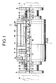
- Fig. 1 is a partial sectional front view, of which upper half if sectioned along the center line.
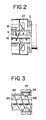
- Fig. 2 is a partial sectional view mainly showing other embodiment of a cooling device.
- Fig. 3 is a partial sectional view of other embodiment to rotate the mixing element.
- The inline mixer of this invention can be applied to inline mixers having various kinds of mixing elements. The following is one of the embodiments, in which this invention is applied to a static mixer.
- In Figs.1 - 3, a main body (1) is so formed that it is connectable with pipe lines (4) by means of flanges (2), (3), having a rotary cylinder (5) within the body. The rotary cylinder may be rotatably supported by various means,and in the drawings, both ends are supported by rotary joint mechanism. Namely, in the drawing, left hand end portion of the rotary cylinder has a flange (6), which is fixed to a flange (8) of a cylindrical rotary shaft (7), and this shaft is supported by bearings (9) such as ball bearings and the like. On the end of the rotary shaft (7), a protecting tube (10) is inserted, and the outer periphery of the protecting tube sheets (11) of Teflon and the like and springs (12) are provided; and seal rings (13), (14) and O-rings (15) are provided between the rotary shaft (7) and the sheet (11) to seal there. In the drawing, the right side of the rotary cylinder is supported by nearly the same construction as that of the left side, and is carried on the main body by a bearing (9) such as ball bearings and the like, and a protecting tube (10) is inserted in its end, and the outer periphery of the protecting tube is provided with sheets (11), a spring (12), and seal rings (13), (14) and an O-ring (15) are provided between the sheet (11) and the rotary cylinder.
- Within the rotary cylinder, a longitudinally extending mixing element (16) is provided. This element (16) has a plurality of wings, with a right twist wind and a left twist wing disposed alternately at the periphery of a shaft, and is fixed to the main body at its both ends. Inside of the rotary shaft (7), an impeller (17) is provided to feed the fluid within the pipe line in the direction of the mixing element (16).
- The rotary cylinder (5) is rotated by a driving means. In the drawing, on the outer periphery of the rotary cylinder, an electro-magnetic coil (18), which generates rotary movable magnetic field, is provided. The whole rotary cylinder or at least a portion corresponding to the electro-magnetic coil is is formed of suitable conductor material such as iron, silicon steel, amorphous and the like, to rotate the rotary cylinder by electro-magnetic induction of the magnetic coil. On the outside of the electro-magnetic coil (18), preferably a jacket (19) is provided, and cooling medium such as water and the like is circulated from an inlet (20) to an outlet (21) to absorb heat generated by the coil.
- In place of a cooling device of water cooling type as shown in the drawing, a cooling device of air cooling type may be provided. In this case, for instance, an air cooling fan may be provided on the outer periphery of the rotary cylinder to send air from the fan to the oil (18) for cooling (Fig. 2). As a driving means, a motor may be used through a belt and gears.
- And, when the electro-magnetic coil (18) is electrified, rotary movable magnetic field is generated, and by electro-magnetic inductive action, the rotary cylinder (5) rotates. When the impeller (17) connected with the rotary cylinder rotates, thereby pumping action is given to the fluid flowing through the pipe line(4), and the fluid is fed in the direction of the mixing element (16). And, as usual, the fluid may be sent by pressure by a separately provided pump, and in this case, the impeller may be eliminated. The fluid sent to the mixing element (16) is divided by the element to inverse as right twist and left twist, and the flowchanges from central portion to the wall portion of the rotary cylinder and vice versa along the twisted surface of the element, thus an axial mixing is effected. Whereupon, because of the rotation of the rotary cylinder, the fluid never stagnate near the wall portion, and in case of non-Newtonian fluid such as pseudo-plastic fluid, plastic fluid and the like, considerable stirring effect can be obtained compared with the usual one.
- While the above embodiment is the case of this invention applied to a static mixer, it is also possible to provide a stirrin blade(23) such as a ribbon screw within a tube (24) as a mixing element and to fix (26) the blade to a rotary cylinder (25) provided in succession to the tube (Fig. 3).
- In such an arrangement, when an electro-magnetic coil (27), which generates rotary movable magnetic field provided on the outer periphery of the rotary cylinder (25), is electrified, the stirring blade (23) is made to rotate within the tube (24) and the smooth flow of the fluid is promoted to enable stirring and mixing.
- As mentioned above, this invention is simple in construction, and may be made compactly, and by rotating the pipe wall with electro-magnetic inductive action, stirring effect may be taken.
- And, if the impeller is provided on the rotary cylinder, the fluid may be sent, so that the usual pump may be eliminated.
Claims (5)
a main body to be fitted on the way of a pipeline;
a mixing element prepared within said main body;
a rotary cylinder surrounding said mixing element; and
a driving means rotating said rotary cylinder.
a main body to be fitted on the way of a pipeline;
a mixing element prepared within said main body;
a rotary cylinder surrounding said mixing element and made of conductor material; and
an electro-magnetic coil being provided on the outer periphery of said rotary cylinder and generating rotary movable magnetic field so as to rotate said rotary cylinder by the electro-magnetic inductive action.
Applications Claiming Priority (2)
| Application Number | Priority Date | Filing Date | Title |
|---|---|---|---|
| JP60256547A JPS62117623A (en) | 1985-11-18 | 1985-11-18 | Inline mixer |
| JP256547/85 | 1985-11-18 |
Publications (3)
| Publication Number | Publication Date |
|---|---|
| EP0223197A2 true EP0223197A2 (en) | 1987-05-27 |
| EP0223197A3 EP0223197A3 (en) | 1988-10-05 |
| EP0223197B1 EP0223197B1 (en) | 1991-08-28 |
Family
ID=17294152
Family Applications (1)
| Application Number | Title | Priority Date | Filing Date |
|---|---|---|---|
| EP86115732A Expired - Lifetime EP0223197B1 (en) | 1985-11-18 | 1986-11-12 | Inline mixer |
Country Status (4)
| Country | Link |
|---|---|
| US (1) | US4729664A (en) |
| EP (1) | EP0223197B1 (en) |
| JP (1) | JPS62117623A (en) |
| DE (1) | DE3681118D1 (en) |
Cited By (3)
| Publication number | Priority date | Publication date | Assignee | Title |
|---|---|---|---|---|
| CN102056654A (en) * | 2008-05-08 | 2011-05-11 | 蓝星环境股份有限公司 | Device for mixing gas into a flowing liquid |
| CN107020030A (en) * | 2017-05-02 | 2017-08-08 | 华南农业大学 | The board-like online medicine mixer of spiral bee-hole and online medicine spraying system mixed in real time |
| CN111043503A (en) * | 2019-12-31 | 2020-04-21 | 贵州南科中控科技有限公司 | Telescoping device for display screen |
Families Citing this family (12)
| Publication number | Priority date | Publication date | Assignee | Title |
|---|---|---|---|---|
| US5887975A (en) * | 1997-09-30 | 1999-03-30 | The Boeing Company | Multiple component in-line paint mixing system |
| US6203183B1 (en) | 1999-04-23 | 2001-03-20 | The Boeing Company | Multiple component in-line paint mixing system |
| US7168846B1 (en) * | 2004-01-20 | 2007-01-30 | Lyco Manufacturing, Inc. | Rotary processing device |
| WO2009123197A1 (en) * | 2008-03-31 | 2009-10-08 | 株式会社日本触媒 | Method of manufacturing particulate water absorbent with water-absorbent resin as main ingredient, and manufacturing apparatus therefor |
| TW201604465A (en) | 2010-06-15 | 2016-02-01 | 拜歐菲樂Ip有限責任公司 | Methods, devices and systems for extraction of thermal energy from a heat conducting metal conduit |
| US8603789B2 (en) | 2011-03-18 | 2013-12-10 | Iogen Energy Corporation | Method for introducing cellulase enzyme to lignocellulosic feedstock slurry |
| TWI525184B (en) | 2011-12-16 | 2016-03-11 | 拜歐菲樂Ip有限責任公司 | Cryogenic injection compositions, systems and methods for cryogenically modulating flow in a conduit |
| TWI583880B (en) | 2013-09-13 | 2017-05-21 | 拜歐菲樂Ip有限責任公司 | Magneto-cryogenic valves, systems and methods for modulating flow in a conduit |
| FR3013993B1 (en) * | 2013-11-29 | 2016-03-04 | Bostik Sa | INSTALLATION AND CORRESPONDING METHOD FOR HOT APPLICATION OF AN ADHESIVE COMPOSITION, DEVICE FOR HEATING A FLUID AND USE THEREOF |
| FR3015315B1 (en) * | 2013-12-19 | 2016-02-12 | Bostik Sa | PROCESS FOR HOT APPLICATION OF SILYLATED ADHESIVE COMPOSITION |
| KR102440432B1 (en) * | 2014-05-30 | 2022-09-05 | 마루젠 세끼유가가꾸 가부시키가이샤 | Apparatus and method for producing cyclic carbonate |
| CN108043271A (en) * | 2017-12-29 | 2018-05-18 | 郑州默尔电子信息技术有限公司 | A kind of feed mixing apparatus based on electromagnetic drive type |
Citations (5)
| Publication number | Priority date | Publication date | Assignee | Title |
|---|---|---|---|---|
| US2826794A (en) * | 1951-07-19 | 1958-03-18 | Junkerather Gewerkshaft | Apparatus for the preparation and mixing of foundry moulding materials |
| CH483275A (en) * | 1967-07-13 | 1969-12-31 | Wuerfel Basler Arnold Kuster | Device for continuous mixing and simultaneous further transport of powder and granulate bulk goods |
| FR2196190A1 (en) * | 1972-08-14 | 1974-03-15 | Tec Group | |
| DE2356595A1 (en) * | 1973-11-13 | 1975-05-22 | Egon R Erdmann | Stationary mixer esp. for milk and fruit products - is long annular chamber containing deflector blades to divide flow |
| JPS5230970A (en) * | 1975-09-04 | 1977-03-09 | Hitachi Ltd | Drum can driving device |
Family Cites Families (8)
| Publication number | Priority date | Publication date | Assignee | Title |
|---|---|---|---|---|
| US3216345A (en) * | 1962-04-09 | 1965-11-09 | Canadian Breweries Ltd | Continuous preparation of brewers' mash |
| FR1532560A (en) * | 1967-05-31 | 1968-07-12 | Fives Lille Cail | Mixer |
| DE2233815A1 (en) * | 1972-07-10 | 1974-01-31 | Basf 6700 Ludwigshafen | DEVICE FOR THE CONTINUOUS TREATMENT AND PROCESSING OF SOLID AND / OR LIQUID MATERIAL |
| CH602172A5 (en) * | 1975-10-10 | 1978-07-31 | Fischer Ag Georg | |
| SU921615A1 (en) * | 1979-08-07 | 1982-04-23 | Коми Государственный Проектный И Научно-Исследовательский Институт Лесной Промышленности | Dispenser |
| US4330216A (en) * | 1980-11-21 | 1982-05-18 | Becton, Dickinson And Company | Gravity-induced stirring device for rotating liquid containers |
| US4444509A (en) * | 1981-04-13 | 1984-04-24 | Sevenson Company | Feed mixing apparatus |
| US4474478A (en) * | 1983-11-30 | 1984-10-02 | Delong George F | Batch mixer for mixing livestock feeds |
-
1985
- 1985-11-18 JP JP60256547A patent/JPS62117623A/en active Granted
-
1986
- 1986-11-12 DE DE8686115732T patent/DE3681118D1/en not_active Expired - Fee Related
- 1986-11-12 EP EP86115732A patent/EP0223197B1/en not_active Expired - Lifetime
- 1986-11-14 US US06/931,240 patent/US4729664A/en not_active Expired - Lifetime
Patent Citations (5)
| Publication number | Priority date | Publication date | Assignee | Title |
|---|---|---|---|---|
| US2826794A (en) * | 1951-07-19 | 1958-03-18 | Junkerather Gewerkshaft | Apparatus for the preparation and mixing of foundry moulding materials |
| CH483275A (en) * | 1967-07-13 | 1969-12-31 | Wuerfel Basler Arnold Kuster | Device for continuous mixing and simultaneous further transport of powder and granulate bulk goods |
| FR2196190A1 (en) * | 1972-08-14 | 1974-03-15 | Tec Group | |
| DE2356595A1 (en) * | 1973-11-13 | 1975-05-22 | Egon R Erdmann | Stationary mixer esp. for milk and fruit products - is long annular chamber containing deflector blades to divide flow |
| JPS5230970A (en) * | 1975-09-04 | 1977-03-09 | Hitachi Ltd | Drum can driving device |
Non-Patent Citations (1)
| Title |
|---|
| PATENT ABSTRACTS OF JAPAN (M-77)[2136], 4th September 1975; & JP-A-52 030 970 (HITACHI SEISAKUSHO K.K.) 09-03-1977 * |
Cited By (5)
| Publication number | Priority date | Publication date | Assignee | Title |
|---|---|---|---|---|
| CN102056654A (en) * | 2008-05-08 | 2011-05-11 | 蓝星环境股份有限公司 | Device for mixing gas into a flowing liquid |
| CN102056654B (en) * | 2008-05-08 | 2014-04-23 | 蓝星环境股份有限公司 | Device for mixing gas into a flowing liquid |
| CN107020030A (en) * | 2017-05-02 | 2017-08-08 | 华南农业大学 | The board-like online medicine mixer of spiral bee-hole and online medicine spraying system mixed in real time |
| CN111043503A (en) * | 2019-12-31 | 2020-04-21 | 贵州南科中控科技有限公司 | Telescoping device for display screen |
| CN111043503B (en) * | 2019-12-31 | 2021-03-30 | 贵州南科中控科技有限公司 | Telescoping device for display screen |
Also Published As
| Publication number | Publication date |
|---|---|
| JPS62117623A (en) | 1987-05-29 |
| EP0223197A3 (en) | 1988-10-05 |
| US4729664A (en) | 1988-03-08 |
| JPH027691B2 (en) | 1990-02-20 |
| EP0223197B1 (en) | 1991-08-28 |
| DE3681118D1 (en) | 1991-10-02 |
Similar Documents
| Publication | Publication Date | Title |
|---|---|---|
| EP0223197A2 (en) | Inline mixer | |
| US7690833B2 (en) | Heat exchange method and apparatus utilizing chaotic advection in a flowing fluid to promote heat exchange | |
| US5141327A (en) | Stirrer | |
| KR100527256B1 (en) | Device for mixing a flowable or pourable medium especially a highly viscous medium | |
| US3650510A (en) | Mixing and aerating apparatus for plastics | |
| US2274274A (en) | Fluid pump and metering device | |
| US4334788A (en) | Pin action mixing pump | |
| US4482253A (en) | Rotary material processor | |
| EP0774293B1 (en) | A cooling device | |
| EP1985357A1 (en) | Method and apparatus for processing liquids under cavitation conditions | |
| US2552889A (en) | Rotor for dispersion machines | |
| US4110059A (en) | Pumping device | |
| US4326811A (en) | Sealess pressurized mixing vessels | |
| US3765481A (en) | Heat exchanger and mixer | |
| JPS61287432A (en) | Pipe line stirring apparatus | |
| EP0220788A2 (en) | Liquid flow mixer | |
| CN210187157U (en) | Reaction kettle | |
| JPS60153930A (en) | Continuous mixing and stirring apparatus for fluid | |
| JPS6212410Y2 (en) | ||
| AU704494B2 (en) | A cooling device | |
| JPS6451131A (en) | Method and apparatus for stirring and mixing fluids | |
| SU1710110A1 (en) | Static mixer | |
| SU1219125A1 (en) | Hydrodynamic radiator | |
| SU1230659A2 (en) | Cavitation mixer | |
| KR910002598Y1 (en) | Mixers for solids |
Legal Events
| Date | Code | Title | Description |
|---|---|---|---|
| PUAI | Public reference made under article 153(3) epc to a published international application that has entered the european phase |
Free format text: ORIGINAL CODE: 0009012 |
|
| AK | Designated contracting states |
Kind code of ref document: A2 Designated state(s): DE FR GB IT |
|
| 17P | Request for examination filed |
Effective date: 19870626 |
|
| PUAL | Search report despatched |
Free format text: ORIGINAL CODE: 0009013 |
|
| AK | Designated contracting states |
Kind code of ref document: A3 Designated state(s): DE FR GB IT |
|
| 17Q | First examination report despatched |
Effective date: 19890928 |
|
| GRAA | (expected) grant |
Free format text: ORIGINAL CODE: 0009210 |
|
| ITF | It: translation for a ep patent filed |
Owner name: BARZANO' E ZANARDO MILANO S.P.A. |
|
| AK | Designated contracting states |
Kind code of ref document: B1 Designated state(s): DE FR GB IT |
|
| REF | Corresponds to: |
Ref document number: 3681118 Country of ref document: DE Date of ref document: 19911002 |
|
| ET | Fr: translation filed | ||
| PLBE | No opposition filed within time limit |
Free format text: ORIGINAL CODE: 0009261 |
|
| STAA | Information on the status of an ep patent application or granted ep patent |
Free format text: STATUS: NO OPPOSITION FILED WITHIN TIME LIMIT |
|
| 26N | No opposition filed | ||
| PGFP | Annual fee paid to national office [announced via postgrant information from national office to epo] |
Ref country code: FR Payment date: 19920930 Year of fee payment: 7 |
|
| PGFP | Annual fee paid to national office [announced via postgrant information from national office to epo] |
Ref country code: GB Payment date: 19921106 Year of fee payment: 7 |
|
| PGFP | Annual fee paid to national office [announced via postgrant information from national office to epo] |
Ref country code: DE Payment date: 19930121 Year of fee payment: 7 |
|
| PG25 | Lapsed in a contracting state [announced via postgrant information from national office to epo] |
Ref country code: GB Effective date: 19931112 |
|
| GBPC | Gb: european patent ceased through non-payment of renewal fee |
Effective date: 19931112 |
|
| PG25 | Lapsed in a contracting state [announced via postgrant information from national office to epo] |
Ref country code: FR Effective date: 19940729 |
|
| PG25 | Lapsed in a contracting state [announced via postgrant information from national office to epo] |
Ref country code: DE Effective date: 19940802 |
|
| REG | Reference to a national code |
Ref country code: FR Ref legal event code: ST |
|
| PG25 | Lapsed in a contracting state [announced via postgrant information from national office to epo] |
Ref country code: IT Free format text: LAPSE BECAUSE OF NON-PAYMENT OF DUE FEES;WARNING: LAPSES OF ITALIAN PATENTS WITH EFFECTIVE DATE BEFORE 2007 MAY HAVE OCCURRED AT ANY TIME BEFORE 2007. THE CORRECT EFFECTIVE DATE MAY BE DIFFERENT FROM THE ONE RECORDED. Effective date: 20051112 |