EP0222979B1 - Femoral component of a hip joint - Google Patents
Femoral component of a hip joint Download PDFInfo
- Publication number
- EP0222979B1 EP0222979B1 EP86110508A EP86110508A EP0222979B1 EP 0222979 B1 EP0222979 B1 EP 0222979B1 EP 86110508 A EP86110508 A EP 86110508A EP 86110508 A EP86110508 A EP 86110508A EP 0222979 B1 EP0222979 B1 EP 0222979B1
- Authority
- EP
- European Patent Office
- Prior art keywords
- femoral component
- component according
- shank
- tie rod
- collar
- Prior art date
- Legal status (The legal status is an assumption and is not a legal conclusion. Google has not performed a legal analysis and makes no representation as to the accuracy of the status listed.)
- Expired - Lifetime
Links
Images


Classifications
-
- A—HUMAN NECESSITIES
- A61—MEDICAL OR VETERINARY SCIENCE; HYGIENE
- A61F—FILTERS IMPLANTABLE INTO BLOOD VESSELS; PROSTHESES; DEVICES PROVIDING PATENCY TO, OR PREVENTING COLLAPSING OF, TUBULAR STRUCTURES OF THE BODY, e.g. STENTS; ORTHOPAEDIC, NURSING OR CONTRACEPTIVE DEVICES; FOMENTATION; TREATMENT OR PROTECTION OF EYES OR EARS; BANDAGES, DRESSINGS OR ABSORBENT PADS; FIRST-AID KITS
- A61F2/00—Filters implantable into blood vessels; Prostheses, i.e. artificial substitutes or replacements for parts of the body; Appliances for connecting them with the body; Devices providing patency to, or preventing collapsing of, tubular structures of the body, e.g. stents
- A61F2/02—Prostheses implantable into the body
- A61F2/30—Joints
- A61F2/32—Joints for the hip
- A61F2/36—Femoral heads ; Femoral endoprostheses
- A61F2/3662—Femoral shafts
-
- A—HUMAN NECESSITIES
- A61—MEDICAL OR VETERINARY SCIENCE; HYGIENE
- A61F—FILTERS IMPLANTABLE INTO BLOOD VESSELS; PROSTHESES; DEVICES PROVIDING PATENCY TO, OR PREVENTING COLLAPSING OF, TUBULAR STRUCTURES OF THE BODY, e.g. STENTS; ORTHOPAEDIC, NURSING OR CONTRACEPTIVE DEVICES; FOMENTATION; TREATMENT OR PROTECTION OF EYES OR EARS; BANDAGES, DRESSINGS OR ABSORBENT PADS; FIRST-AID KITS
- A61F2/00—Filters implantable into blood vessels; Prostheses, i.e. artificial substitutes or replacements for parts of the body; Appliances for connecting them with the body; Devices providing patency to, or preventing collapsing of, tubular structures of the body, e.g. stents
- A61F2/02—Prostheses implantable into the body
- A61F2/30—Joints
- A61F2002/30001—Additional features of subject-matter classified in A61F2/28, A61F2/30 and subgroups thereof
- A61F2002/30316—The prosthesis having different structural features at different locations within the same prosthesis; Connections between prosthetic parts; Special structural features of bone or joint prostheses not otherwise provided for
- A61F2002/30535—Special structural features of bone or joint prostheses not otherwise provided for
- A61F2002/30579—Special structural features of bone or joint prostheses not otherwise provided for with mechanically expandable devices, e.g. fixation devices
Definitions
- the invention relates to a shaft part of a hip joint with an essentially spherical shaft head and a shaft which adjoins this via a collar and which, following the collar, has a curvature in the direction of its lower end and by means of a tensioning device designed as a pull rod in a medullary cavity Thigh bone is attachable.
- Such a shaft part is known from FR-A-243 3 932, which is fastened without cement in a medullary sheath of a femur. It is fastened with the help of screw connections that extend from the collar of the prosthesis towards reinforcement plates that strengthen the femur laterally and medially. These screw connections tighten the collar of the prosthesis in these plates, which are attached to the outside of the femur.
- screw connections are provided which are designed as bone screws and protrude through corresponding holes in the plates and connect them to the bone.
- the lower edge of the collar of the shaft part lies positively on the corresponding resection surface of the bone. If the medullary bone of the femur is not carefully enough adapted to the shaft, so that it has a slight clearance within the medullary cavity, which is to be expected, then movement of the prosthesis within the medullary cavity can only be achieved by a firm fit of the collar the resection area are prevented. However, since this contact surface is comparatively small, and in addition the lower part of the collar is pressed with this section surface only at two opposite points of the collar, it must be expected that the short stem within the medullary cavity loosens very quickly under the considerable alternating loads that act on the femoral head. This creates pain for the patient and very soon a complete loosening and inoperability of the entire shaft part can be expected. Over its entire length, this has no design that could bring about a positive connection between the stem and the bone surrounding it.
- the object of the present invention is therefore to improve the shaft part of a hip joint of the type mentioned in the introduction in such a way that a transmission of the forces introduced into the shaft is largely uniformly ensured over the entire cross section of the shaft.
- the shaft has in its surface rectilinearly extending grooves in its longitudinal direction for positive connection with the bone mass surrounding the shaft surface, and that the shaft at its upper end adjacent to the collar in the medullary cavity with the trained as a pull rod Clamping device can be clamped, which clamping device can be supported in the relaxed state against the shaft on the one hand and the medullary cavity on the other hand.
- the positive connection of the shaft surface with the surrounding bone mass ensures that loosening of the shaft part within the medullary cavity is avoided.
- the bracing of the shaft part of the medullary cavity leads to a firm anchoring and thus to a largely uniform pressure load of the shaft within the medullary cavity. This even pressure load promotes the formation of bone tissue, which forms evenly around the entire shaft. In this way, a balancing between the zones of higher pressure load and lower pressure load can take place.
- grooves extending in the surface in the longitudinal direction of the shaft extend. These grooves significantly enlarge the surface of the shaft part and thus improve an intimate connection between the medullary cavity and the surface of the shaft.
- the shaft is clamped at its upper end adjacent to the collar with a tensioning device in a medullary cavity of a femur surrounding it.
- This tension lies in an area in which only a small force is transmitted from the shaft to the thigh in the case of an untensioned shaft.
- the bracing thus compensates for this unequal pressure load on the shaft, so that a moment of uprighting of the shaft in the medullary cavity is generated by the bracing. This moment ensures that the compressive forces occurring in the inner region of the curvature are reduced and are transmitted from the outer region of the shaft to the bone.
- This pressure equalization results from a frictional connection in the direction of the prosthesis head.
- the uniform loading of the surface of the shaft over its entire cross-section means that loosening of the shaft within the medullary cavity is avoided.
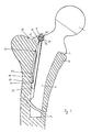
- the collar 3 On its upper side 16 facing the shaft head 1, the collar 3 opens into an annular depression 17 from which the shaft head 1 with its spherical surface 18 rises.
- This spherical surface 18 is rotatably supported in a hip socket, not shown, which is embedded in a pelvic bone, also not shown.
- a recess 19 extends through the shaft 2, which extends in the form of a secant through the outer radius of curvature 11.
- This secant begins approximately in the region of the opening of the outer radius of curvature 11 into the collar 3 and ends in a region in which the outer radius of curvature 11 opens into a straight end piece 2o which extends in the direction of the lower end 9 of the shaft part.
- This straight end piece 2o has a length that is approximately 1.5 times greater than the outer curvature 11.
- the recess 19 is designed as a cavity 21 which is open on its side facing the outer radius of curvature 11. This cavity 21 has a different depth in its cross section.
- This depth is the smallest in the area of the collar 3 and at an end 22 of the cavity 21 opposite the collar. Between the collar 3 and the end 22, the depth of the cavity 21 passes through a maximum 23. In the area of this maximum 23, opposite side walls 24, 25 of the cavity 21 are formed the highest. These side walls 24, 25 converge in the interior of the shaft 2 to form an arc 26 which is opposite an opening 27 of the recess 19.
- a clamping device 28 is guided in this cavity 21.
- This consists essentially of a pull rod 29 and a shield 3o, which is coupled to the pull rod 29 via a catch 31.
- This driver catch 31 is attached to the pull rod 29.
- the driver catch 31 is fastened to a lower end 32 of the pull rod 29 facing away from the collar 3.
- the driver catch 31 is designed in the form of a tooth 33 which extends on the driver catch 31 in a direction facing away from the circular arc 26. This tooth 33 rises in a direction of the pull rod 29 facing away from the end 32.
- the pull rod can be cylindrical, for example, and projects with its upper end 34 facing away from the lower end 32 through a bore 35 provided in the collar 3. This bore 35 extends in the direction of the cavity 21 through the collar 3.
- the bore 35 is widened to form a seat 37.
- This seat is so far embedded in the collar 3 that 3 lateral walls 38 are formed within the collar, on which an elastic intermediate layer 39 is guided is.
- This elastic intermediate layer 39 can consist, for example, of a silicone.
- the upper end 34 of the pull rod 29 projects through this elastic intermediate layer 39 and is supported on the elastic intermediate layer 39 by means of a washer 40 with a clamping nut 41.
- the bore 35 surrounds the pull rod 29 with a play that is large enough to allow movements of the pull rod 29 which are transverse to the longitudinal direction of the pull rod. Such movements are absorbed by the elastic intermediate layer 39.
- the bore 35 is expediently designed in the form of a cone which widens in the direction of the cavity 21, so that the pull rod can carry out pivotal movements within the cavity 21 about its upper end 34.
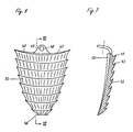
- the shield 3o is provided on its outer surface 42 facing away from the pull rod 29 with teeth 43 which extend in mutually parallel rows transverse to the longitudinal direction of the pull rod 29. These teeth 43 rise with their cutting edges 44 in the direction of the upper end 34 of the pull rod 29.
- the shield 3o is curved in the form of an arc around the pull rod 29. In this way, it receives a curvature 45, which allows the shield 3o to be in large contact with a marrow cavity prepared for receiving the shaft 2.
- the shield 30 With its lower end 46 facing away from the upper end 34, the shield 30 lies on the catch 31. In the direction of its upper end 47, the shield 3o widens like a shield. At the upper end 47 an eyelet 48 is provided which lies approximately on a center line extending through the shield 3o. A bore 49 extends through this eyelet 48, the cross section of which is dimensioned such that the pull rod 29 can pass through it with play.
- the shield 3o with bearing surfaces 5o, 51 rests on the shaft 2 on both sides of the cavity 21. Along these contact surfaces 51 the shield 3o slides in the longitudinal direction of the shaft 2 when it is raised in the direction of the collar 3 with the aid of the pull rod 29.
- two pressure surfaces 52, 53 are formed on the shaft, on which the bearing surfaces 5o, 51 rest. These pressure surfaces 52, 53 are formed at at least two points as inclined planes 54, 55, which rise in the direction of the shield 3o. The elevations of the inclined planes 54, 55 run in the direction of the collar 3.
- the shield 3o coupled to the pull rod 29 via the driver catch 31 is raised with this in the direction of the collar 3, the shield 3o with its contact surfaces 5o, 51 runs on the inclined planes 54, 55 applied to the pressure surfaces 52, 53, so that the shield 3o executes a tilting movement directed away from the pull rod 29 around its lower end 46. It is guided in the longitudinal direction of the pull rod 29 on the eyelet 48. This tilting movement gives the teeth 43 an inclination in the direction of the medullary cavity extending through the femur 13, in the walls of which they can burrow when the clamping nut 41 is further tightened. In this way, a tensioning force which braces the shaft 2 in the medullary cavity is exerted by the medullary cavity on the shaft 2 via the shield 30 and the pull rod 29.
- the collar 3 lies firmly with the teeth 12 on a support surface 56 prepared on the femur 13. These teeth 12 dig into the bearing surface 56 and in this way prevent the shaft part 13 from being able to perform pivoting movements around its end 9 within the medullary cavity of the femur 13.
- 2 grooves 57 are provided in the shaft 2 for further guidance of the shaft anchored in the marrow cavity without cement. These grooves 57 run parallel to one another in the longitudinal direction of the shaft 2.
- the direction of the lower end piece 2o is provided as the longitudinal direction of the shaft 2, the grooves 57 of which extend parallel to the outer surface 58 facing the outer radius of curvature 11.
- the grooves 57 have approximately the same mutually Widths.
- Sharp edges 59 are formed between the individual grooves 57, which cut into the femur 13 when the shaft 2 is inserted into the medullary cavity. In this way, the shaft 2 receives a fixed alignment with respect to the thigh bone 13, without the rotational forces or swiveling movements within the thigh bone 13 being able to be carried out by the forces introduced into the shaft head 1.
- the grooves 57 not only run parallel to one another, but are also aligned in a straight line.
- a correspondingly large recess is first prepared in the area of the medullary cavity.
- the shaft 2 is then inserted into the prepared medullary cavity.
- Both the tie rod 29 and the shield 3o have their respective lower ends 32, 46 inserted as far as possible into the cavity 21.
- the shield 3o lies with its support surfaces 5o, 51 on the pressure surfaces 52, 53 in an area which extends in the direction of the end 46 of the shield 3o below the inclined planes 54, 55.
- the clamping nut 41 is screwed in the direction of the elastic intermediate layer 39 so that a pull is exerted on the pull rod 29.
- the shield 3o runs with its contact surfaces 5o, 51 over the pressure surfaces 52, 53 and reaches the area of the inclined planes 54, 55.
- the inclined planes 54, 55 lift the shield 3o in the direction of the marrow cavity adjacent to the teeth 43, see above that the teeth claw firmly in the medullary cavity of the femur 13 when tightening the clamping nut 41 further.
- the bore 35 which is designed in the form of a cone, permits such pendulum movements of the pull rod 29.
- deformations in the area of the clamping nut 41 can be absorbed by the elastic intermediate layer 39 .
- the recess 19 can also be designed as a closed bore in the direction of the side 7 of the shaft 2. It is only important that the cavity at its lower end 22 is so open due to the formation of the outer radius of curvature 11 that a displacement of the driver catch 31 is possible. This shift must be able to take place over a length that allows the shield 3o to be braced within the marrow cavity.
Abstract
Description
Die Erfindung betrifft einen Schaftteil eines Hüftgelenkes mit einem im wesentlichen kugeligen Schaftkopf und einem sich über einen Kragen an diesen anschließenden Schaft, der im Anschluß an den Kragen in Richtung auf sein unteres Ende eine Krümmung aufweist und mittels einer als Zugstange ausgebildeten Spannvorrichtung in einer Markhöhle eines Oberschenkelknochens befestigbar ist.The invention relates to a shaft part of a hip joint with an essentially spherical shaft head and a shaft which adjoins this via a collar and which, following the collar, has a curvature in the direction of its lower end and by means of a tensioning device designed as a pull rod in a medullary cavity Thigh bone is attachable.
Aus der FR-A-243 3 932 ist ein solcher Schaftteil bekannt, der zementlos in einer Markhülle eines Oberschenkelknochens befestigt wird. Die Befestigung erfolgt mit Hilfe von Schraubverbindungen, die sich vom Kragen der Prothese in Richtung auf Verstärkungsplatten erstrecken, die lateral und medial den Femurknochen stärken. Diese Schraubverbindungen spannen den Kragen der Prothese in diesen Platten, die außen auf dem Femurknochen besfestigt sind. Zur Befestigung der Platten auf dem Femurknochen sind Schraubverbindungen vorgesehen, die als Knochenschrauben ausgebildet sind und durch entsprechende Löcher der Platten hindurchragen und diese mit dem Knochen verbinden.Such a shaft part is known from FR-A-243 3 932, which is fastened without cement in a medullary sheath of a femur. It is fastened with the help of screw connections that extend from the collar of the prosthesis towards reinforcement plates that strengthen the femur laterally and medially. These screw connections tighten the collar of the prosthesis in these plates, which are attached to the outside of the femur. To attach the plates to the femur, screw connections are provided which are designed as bone screws and protrude through corresponding holes in the plates and connect them to the bone.
Der Kragen des Schaftteiles liegt mit seiner Unterkante formschlüssig auf der entsprechenden Resektionsfläche des Knochens auf. Sollte die Markhöhle des Femurknochens nicht sorgfältig genug dem Schaft angepaßt sein, so daß dieser innerhalb der Markhöhle ein, wenn auch nur geringes Spiel aufweist, womit zu rechnen ist, dann kann eine Bewegung der Prothese innerhalb der Markhöhle nur durch einen festen Sitz des Kragens auf der Resektionsfläche unterbunden werden. Da jedoch diese Auflagefläche vergleichsweise klein ist, und außerdem eine Verpressung der Kragenunterseite mit dieser Sektionsfläche nur an zwei einander gegenüberliegenden Stellen des Kragens erfolgt, muß damit gerechnet werden, daß sich der ohnehin recht kurze Stiel innerhalb der Markhöhle unter den erheblichen Wechselbelastungen, die auf den Hüftkopf einwirken, sehr bald lockert. Dadurch entstehen Schmerzen für den Patienten und sehr bald ist mit einer vollkommenen Lockerung und Funktionsunfähigkeit des gesamten Schaftteiles zu rechnen. Dieser besitzt auf seiner gesamten Länge keine Ausbildung, die eine formschlüssige Verbindung des Stiels mit dem ihm umgebenden Knochen herbeiführen könnte.The lower edge of the collar of the shaft part lies positively on the corresponding resection surface of the bone. If the medullary bone of the femur is not carefully enough adapted to the shaft, so that it has a slight clearance within the medullary cavity, which is to be expected, then movement of the prosthesis within the medullary cavity can only be achieved by a firm fit of the collar the resection area are prevented. However, since this contact surface is comparatively small, and in addition the lower part of the collar is pressed with this section surface only at two opposite points of the collar, it must be expected that the short stem within the medullary cavity loosens very quickly under the considerable alternating loads that act on the femoral head. This creates pain for the patient and very soon a complete loosening and inoperability of the entire shaft part can be expected. Over its entire length, this has no design that could bring about a positive connection between the stem and the bone surrounding it.
Aufgabe der vorliegenden Erfindung ist es daher, den Schaftteil eines Hüftgelenkes der einleitend genannten Art so zu verbesseren, daß eine Übertragung der in den Schaft eingeleiteten Kräfte über den gesamtem Querschnitt des Schaftes weitgehend gleichmäßig gewährleistet ist.The object of the present invention is therefore to improve the shaft part of a hip joint of the type mentioned in the introduction in such a way that a transmission of the forces introduced into the shaft is largely uniformly ensured over the entire cross section of the shaft.
Diese Aufgabe wird erfindungsgemäß dadurch gelöst, daß der Schaft in seiner Oberfläche sich in seiner Längsrichtung geradlinig erstreckende Rillen zur formschlüssigen Verbindung mit der die Schaftoberfläche umgebenden Knochenmasse aufweist, und daß der Schaft an seinem dem Kragen benachbarten oberen Ende in der Markhöhle mit der als Zugstange ausgebildeten Spannvorrichtung verspannbar ist, welche Spannvorrichtung im enstpannten Zustand gegenüber dem Schaft einerseits und der Markhöhle andererseits abstützbar ist.This object is achieved in that the shaft has in its surface rectilinearly extending grooves in its longitudinal direction for positive connection with the bone mass surrounding the shaft surface, and that the shaft at its upper end adjacent to the collar in the medullary cavity with the trained as a pull rod Clamping device can be clamped, which clamping device can be supported in the relaxed state against the shaft on the one hand and the medullary cavity on the other hand.
Die formschlüssige Verbindung der Schaftoberfläche mit der umgebenden Knochenmasse sorgt dafür, daß eine Lockerung des Schaftteils innerhalb der Markhöhle vermieden wird. Die Verspannung des Schaftteiles der Markhöhle führt zu einer festen Verankerung und damit zu einer weitgehend gleichmäßigen Druckbelastung des Schaftes innerhalb der Markhöhle. Diese gleichmäßige Druckbelastung fördert im übrigen die Ausbildung von Knochengewebe, das sich gleichmäßig um den gesamten Schaft ausbildet. Auf diese Weise kann ein Ausgleich zwischen den Zonen höherer Druckbelastung und niedriger Druckbelastung erfolgen.The positive connection of the shaft surface with the surrounding bone mass ensures that loosening of the shaft part within the medullary cavity is avoided. The bracing of the shaft part of the medullary cavity leads to a firm anchoring and thus to a largely uniform pressure load of the shaft within the medullary cavity. This even pressure load promotes the formation of bone tissue, which forms evenly around the entire shaft. In this way, a balancing between the zones of higher pressure load and lower pressure load can take place.
Gemäß einer bevorzugten Ausführungsform der Erfindung verlaufen in der Oberfläche in Längsrichtung des Schaftes sich erstreckende Rillen. Diese Rillen vergrössern die Oberfläche des Schaftteils erheblich und verbessern damit eine innige Verbindung zwischen der Markhöhle und der Oberfläche des Schaftes.According to a preferred embodiment of the invention, grooves extending in the surface in the longitudinal direction of the shaft extend. These grooves significantly enlarge the surface of the shaft part and thus improve an intimate connection between the medullary cavity and the surface of the shaft.
Diese innige Verbindung verhindert eine Lokkerung des Schaftes. Außerdem wird durch die Rillung die Oberfläche des Schaftes vergrößert, so daß dadurch eine Verminderung der Flächenpressung eintritt.This intimate connection prevents the shaft from locating. In addition, the surface of the shaft is increased by the grooving, so that there is a reduction in the surface pressure.
Gemäß einer weiteren bevorzugten Ausführungsform der Erfindung ist der Schaft an seinem dem Kragen benachbarten oberen Ende mit einer Spannvorrichtung in einer ihn umgebenden Markhöhle eines Oberschenkelknochens verspannt. Diese Verspannung liegt in einem Bereich, in dem bei einem unverspannten Schaft nur geringe Kräfte vom Schaft auf den Oberschenkel übertragen werden. Die Verspannung gleicht damit diese ungleiche Druckbelastung des Schaftes aus, so daß von der Verspannung ein den Schaft in der Markhöhle aufrichtendes Moment erzeugt wird. Dieses Moment sorgt dafür, daß die im inneren Bereich der Krümmung auftretenden Druckkräfte vermindert und von dem äußeren Bereich des Schaftes auf den Knochen übertragen werden. Dieser Druckausgleich entsteht durch einen in Richtung auf den Prothesenkopf verlaufenden Kraftschluß. Die gleichmäßige Belastung der Oberfläche des Schaftes über dessen gesamten Querschnitt führt dazu, daß Lockerungen des Schaftes innerhalb der Markhöhle vermieden werden.According to a further preferred embodiment of the invention, the shaft is clamped at its upper end adjacent to the collar with a tensioning device in a medullary cavity of a femur surrounding it. This tension lies in an area in which only a small force is transmitted from the shaft to the thigh in the case of an untensioned shaft. The bracing thus compensates for this unequal pressure load on the shaft, so that a moment of uprighting of the shaft in the medullary cavity is generated by the bracing. This moment ensures that the compressive forces occurring in the inner region of the curvature are reduced and are transmitted from the outer region of the shaft to the bone. This pressure equalization results from a frictional connection in the direction of the prosthesis head. The uniform loading of the surface of the shaft over its entire cross-section means that loosening of the shaft within the medullary cavity is avoided.
Weitere Einzelheiten der Erfindung ergeben sich aus der nachfolgenden ausführlichen Beschreibung und den beigefügten Zeichnungen, in denen bevorzugte Ausführungsformen der Erfindung beispielsweise veranschaulicht sind.Further details of the invention will become apparent from the following detailed description and the accompanying drawings, in which preferred embodiments of the invention are illustrated, for example.
In den Zeichnungen zeigen:
- Fig. 1:
- eine Seitenansicht eines Schaftteils,
- Fig. 2:
- einen Querschnitt durch einen Schaftteil entsprechend der Schnittlinie II-II in Figur 1 in vergrößerter Darstellung,
- Fig. 3:
- einen Längsschnitt durch einen Oberschenkelknochen mit eingebautem Schaftteil,
- Fig. 4:
- einen Querschnitt durch einen Schaftteil entsprechend der Schnittlinie IV-IV in Figur 1,
- Fig. 5:
- einen Querschnitt durch einen Schaftteil entsprechend der Schnittlinie V-V in Figur 1,
- Fig. 6:
- eine räumliche Darstellung eines Schildes und
- Fig. 7:
- einen Längsschnitt durch ein Schild entsprechend der Schnittlinie VII-VII in
Figur 6
- Fig. 1:
- a side view of a shaft part,
- Fig. 2:
- 3 shows a cross section through a shaft part according to section line II-II in FIG. 1 in an enlarged view,
- Fig. 3:
- a longitudinal section through a thigh bone with a built-in shaft part,
- Fig. 4:
- 3 shows a cross section through a shaft part according to section line IV-IV in FIG. 1,
- Fig. 5:
- 2 shows a cross section through a shaft part according to section line VV in FIG. 1,
- Fig. 6:
- a spatial representation of a sign and
- Fig. 7:
- a longitudinal section through a shield according to the section line VII-VII in Figure 6
Auf seiner dem Schaftkopf 1 zugewandten Oberseite 16 mündet der Kragen 3 in eine ringförmigen Mulde 17 ein, aus der sich der Schaftkopf 1 mit seiner kugeligen Oberfläche 18 erhebt. Diese kugelige Oberfläche 18 ist in einer nicht dargestellten Hüftpfanne drehbar gelagert, die in einem ebenfalls nicht dargestellen Beckenknochen eingelassen ist.On its
Im Bereich des äußeren Krümmungsradius 11 erstreckt sich durch den Schaft 2 eine Ausnehmung 19, die in Form einer Sekante sich durch den äußeren Krümmungsradius 11 erstreckt. Diese Sekante beginnt in etwa im Bereich der Einmündung des äußeren Krümmungsradius 11 in den Kragen 3 und endet in einem Bereich, in dem der äußere Krümmungsradius 11 in ein sich in Richtung auf das untere Ende 9 des Schaftteils erstreckendes grades Endstück 2o einmündet. Dieses gerade Endstück 2o besitzt eine Länge, die in etwa 1,5 mal größer als die Außenkrümmung 11 ist. Die Ausnehmung 19 ist als eine Höhlung 21 ausgebildet, die auf ihrer dem äußeren Kürmmungsradius 11 zugewandten Seite offen ist. Diese Höhlung 21 besitzt in ihrem Querschnitt eine unterschiedliche Tiefe. Diese Tiefe ist im Bereich des Kragens 3 und an einem dem Kragen gegenüberliegenden Ende 22 der Höhlung 21 am kleinsten. Zwischen dem Kragen 3 und dem Ende 22 durchschreitet die Tiefe der Höhlung 21 ein Maximum 23. Im Bereich dieses Maximums 23 sind einander gegenüberliegende Seitenwandungen 24, 25 der Höhlung 21 am höchsten ausgebildet. Diese Seitenwandungen 24, 25 laufen im Inneren des Schafts 2 zu einem Kreisbogen 26 zusammen, der einer Öffnung 27 der Ausnehmung 19 gegenüberliegt. In dieser Höhlung 21 wird eine Spannvorrichtung 28 geführt. Diese besteht im wesentlichen aus einer Zugstange 29 und einem Schild 3o, das über eine Mitnehmerraste 31 an die Zugstange 29 angekoppelt ist. Diese Mitnehmerraste 31 ist an der Zugstange 29 befestigt. Die Befestigung der Mitnehmerraste 31 erfolgt an einem dem Kragen 3 abgewandten unteren Ende 32 der Zugstange 29. Die Mitnehmerraste 31 ist in Form eines Zahnes 33 ausgebildet, der sich in einer vom Kreisbogen 26 abgewandten Richtung auf der Mitnehmerraste 31 erstreckt. Dieser Zahn 33 erhebt sich in eine vom Ende 32 abgewandte Richtung der Zugstange 29 aufwärts.In the area of the outer radius of curvature 11, a
Die Zugstange kann beispielsweise zylindrisch ausgebildet sein und ragt mit ihrem dem unteren Ende 32 abgewandten oberen Ende 34 durch eine im Kragen 3 vorgesehene Bohrung 35. Diese Bohrung 35 erstreckt sich in Richtung der Höhlung 21 durch den Kragen 3.The pull rod can be cylindrical, for example, and projects with its upper end 34 facing away from the
Auf ihrem der Höhlung 21 abgewandten oberen Seite 36 ist die Bohrung 35 zu einer Sitzfläche 37 erweitert. Diese Sitzfläche ist in den Kragen 3 soweit eingelassen, daß innerhalb des Kragens 3 seitliche Wandungen 38 ausgebildet sind, an denen eine elastische Zwischenlage 39 gegeführt ist. Diese elastische Zwischenlage 39 kann beispielsweise aus einem Silikon bestehen. Durch diese elastische Zwischenlage 39 ragt das obere Ende 34 der Zugstange 29 hindurch und stützt sich über eine Scheibe 4o mit einer Spannmutter 41 auf der elastischen Zwischenlage 39 ab. Die Bohrung 35 umgibt die Zugstange 29 mit einem Spiel, das groß genug ist, Bewegungen der Zugstange 29 zuzulassen, die quer zur Längsrichtung der Zugstange verlaufen. Derartige Bewegungen werden von der elastischen Zwischenlage 39 aufgenommen. Zweckmäßigerweise ist die Bohrung 35 in Form eines sich in Richtung auf die Höhlung 21 erweiternden Kegels ausgebildet, so daß die Zugstange um ihr oberes Ende 34 Schwenkbewegungen innerhalb derHöhlung 21 ausführen kann.On its
Der Schild 3o ist auf seiner der Zugstange 29 abgewandten Außenfläche 42 mit Zähnen 43 versehen, die sich in einander parallel verlaufenden Reihen quer zur Längsrichtung der Zugstange 29 erstrecken. Diese Zähne 43 erheben sich mit ihren Schneidkanten 44 in Richtung auf das obere Ende 34 der Zugstange 29. Dabei ist der Schild 3o in Form eines Kreisbogens um die Zugstange 29 gewölbt. Es erhält auf diese Weise eine Wölbung 45, die eine großflächige Anlage des Schildes 3o an einer für die Aufnahme des Schaftes 2 vorbereiteten Markhöhle gestattet.The shield 3o is provided on its
Mit seinem dem oberen Ende 34 abgewandten unteren Ende 46 liegt der Schild 3o auf der Mitnehmerraste 31 auf. In Richtung auf sein oberes Ende 47 erweitert sich der Schild 3o schildförmig. Am oberen Ende 47 ist eine Öse 48 vorgesehen, die in etwa auf einer sich durch den Schild 3o erstreckenden Mittellinie liegt. Durch diese Öse 48 erstreckt sich eine Bohrung 49, deren Querschnitt so bemessen ist, daß die Zugstange 29 durch sie hindurch mit Spiel verlaufen kann.With its
Beidseits der Höhlung 21 liegt der Schild 3o mit Auflageflächen 5o, 51 auf dem Schaft 2 auf. Entlang dieser Auflageflächen 51 gleitet der Schild 3o in Längsrichtung des Schaftes 2, wenn er mit Hilfe der Zugstange 29 in Richtung auf den Kragen 3 angehoben wird. Zu diesem Zwecke sind auf dem Schaft 2 Druckflächen 52, 53 ausgebildet, auf denen die Auflageflächen 5o, 51 aufliegen. Diese Druckflächen 52, 53 sind an mindestens zwei Stellen als schiefe Ebenen 54, 55 ausgebildet, die sich in Richtung auf den Schild 3o erheben. Die Erhebungen der schiefen Ebenen 54, 55 verlaufen in Richtung auf den Kragen 3. Wird der über die Mitnehmerraste 31 an die Zugstange 29 angekoppelte Schild 3o mit dieser in Richtung auf den Kragen 3 angehoben, so läuft der Schild 3o mit seinen Auflageflächen 5o, 51 auf die auf den Druckflächen 52, 53 aufgebrachten schiefen Ebenen 54, 55 auf, so daß der Schild 3o eine von der Zugstange 29 weggerichtete Kippbewegung um ihr unteres Ende 46 vollzieht. Sie wird dabei in Längsrichtung der Zugstange 29 an der Öse 48 geführt. Durch diese Kippbewegung erhalten die Zähne 43 eine Neigung in Richtung auf die sich durch den Oberschenkelknochen 13 erstreckende Markhöhle, in deren Wandungen sie sich beim weiteren Anziehen der Spannmutter 41 eingraben können. Auf diese Weise wird über den Schild 3o und die Zugstange 29 eine den Schaft 2 in der Markhöhle verspannende Spannkraft von der Markhöhle auf den Schaft 2 ausgeübt.The shield 3o with bearing
Darüber hinaus liegt der Kragen 3 mit den Zähnen 12 fest auf einer am Oberschenkelknochen 13 vorbereiteten Auflagefläche 56 an. Diese Zähne 12 graben sich in die Auflagefläche 56 ein und verhindern auf diese Weise, daß der Schaftteil innerhalb der Markhöhle des Oberschenkelknochens 13 Schwenkbewegungen um sein Ende 9 ausführen kann. Schließlich sind zur weiteren Führung des zementlos in der Markhöhle verankerten Schaftes 2 Rillen 57 im Schaft 2 vorgesehen. Diese Rillen 57 verlaufen in Längsrichtung des Schaftes 2 einander parallel. Dabei ist als Längsrichtung des Schaftes 2 die Richtung des unteren Endstückes 2o vorgesehen, zu deren dem äuseren Krümmungsradius 11 zugewandten Außenfläche 58 die Rillen 57 parallel verlaufen. Dabei besitzen die Rillen 57 einander etwa gleichbleibende Breiten. Zwischen den einzelnen Rillen 57 sind scharfe Kanten 59 ausgebildet, die sich in den Oberschenkelknochen 13 hineinschneiden, wenn der Schaft 2 in die Markhöhle eingesetzt wird. Auf diese Weise erhält der Schaft 2 eine feste Ausrichtung bezüglich des Oberschenkelknochens 13,ohne daß durch die in den Schaftkopf 1 eingeleiteten Kräfte Dreh- oder Schwenkbewegungen innerhalb des Oberschenkelknochens 13 ausgeführt werden können. Die Rillen 57 verlaufen nicht nur parallel zueinander, sondern sind auch geradlinig ausgerichtet.In addition, the
Wenn der Schaftteil in einen Oberschenkelknochen 13 eingesetzt werden soll, wird zunächst eine entsprechend große Ausnehmung im Bereich der Markhöhle vorbereitet. Sodann wird der Schaft 2 in die vorbereitete Markhöhle eingesetzt. Dabei ist sowohl die Zugstange 29 als auch der Schild 3o mit ihren jeweiligen unteren Enden 32, 46 soweit wie möglich in die Höhlung 21 eingefahren. Der Schild 3o liegt mit seinen Auflageflächen 5o, 51 auf den Druckflächen 52, 53 in einem Bereich auf, der sich in Richtung auf das Ende 46 des Schildes 3o unterhalb der schiefen Ebenen 54, 55 erstreckt. Nachdem die Rillen 57 mit ihren scharfen Kanten 59 und die Zähne 12 mit ihren unteren Flächen 14 sich fest im Oberschenkelknochen 13 verankert haben, wird die Spannmutter 41 in Richtung auf die elastische Zwischenlage 39 verschraubt, so daß ein Zug auf die Zugstange 29 ausgeübt wird. Diese gleitet durch die Höhlung 21 in Richtung auf den Kragen 3 und nimmt dabei den Schild 3o über die Mitnehmerraste 31 mit. Der Schild 3o läuft mit seinen Auflageflächen 5o, 51 über die Druckflächen 52, 53 und gelangt in den Bereich der schiefen Ebenen 54, 55. Die schiefen Ebenen 54, 55 heben den Schild 3o in Richtung auf die den Zähnen 43 benachbarte Markhöhle ab, so daß sich die Zähne beim weiteren Anziehen der Spannmutter 41 fest in der Markhöhle des Oberschenkelknochens 13 verkrallen. Auf diese Weise wird eine Lockerung des Schildes 3o vermieden und der Schaft 2 in der Markhöhle verspannt. Durch diese Verspannung sind die über den äußeren Krümmungsradius 11 in den Oberschenkelknochen 13 eingeleiteten Kräfte etwa gleich groß denjenigen, die über die inneren Krümmungsradius in den Oberschenkelknochen 13 eingeleitet werden. Sollte die Zugstange 29 mit ihrem oberen Ende 34 zu weit aus dem Kragen 3 herausstehen, so wird das überstehende Ende mit einem entsprechenden Werkzeug abgeschnitten. Falls im Rahmen einer Wechseloperation der Schaftteil aus der Markhöhle herausgenommen werden muß,kann die Spannmutter 41 von der Zugstange 29 abgeschraubt und diese in die Höhlung 21 zurückgestoßen werden. Sodann kann der Schaftteil aus der Markhöhle herausgezogen werden, so daß die Zugstange 29 mit ihrem oberen Ende 34 durch die Bohrung 35 hindurchgleitet.If the shaft part is to be inserted into a
Sollten während des Verspannens der Zugstange 29 Bewegungen der Zugstange um ihr oberes Ende 34 notwendig werden, so gestattet die in Form eines Kegels ausgebildete Bohrung 35 derartige Pendelbewegungen der Zugstange 29. Darüber hinaus können Verformungen im Bereich der Spannmutter 41 durch die elastische Zwischenlage 39 aufgenommen werden.If, during tensioning of the
Die Ausnehmung 19 kann auch als eine in Richtung auf die Seite 7 des Schaftes 2 geschlossene Bohrung ausgebildet sein. Dabei ist lediglich wichtig, daß die Höhlung an ihrem unteren Ende 22 aufgrund der Ausbildung des äußeren Krümmungsradius 11 soweit offen ist, daß eine Verschiebung der Mitnehmerraste 31 möglich ist. Diese Verschiebung muß über eine Länge stattfinden können, die eine Verspannung des Schildes 3o innerhalb der Markhöhle gestattet.The
Claims (29)
- A femoral component of a hip joint comprising a substantially spherical femoral head (1) and a shank (2) which is connected thereto by way of a collar (3) and which adjoining the collar (3) has a curvature (8) in a direction towards its lower end (9) and which can be fixed in a marrow cavity of a femur (13) by means of a clamping device (28) in the form of a tie rod (29), characterised in that in its surface the shank (2) has grooves (27) extending rectilinearly in its longitudinal direction for positive connection to the bone material surrounding the shank surface, and that at its upper end adjacent the collar (3) the shank (2) can be braced in the marrow cavity with the clamping device (28) which is in the form of a tie rod (29), which clamping device in the tightened condition can be supported relative to the shank (2) on the one hand and the marrow cavity on the other hand.
- A femoral component according to claim 1 characterised in that the tie rod (29), for applying a clamping force, has a clamping end which extends through a bore (35) in the collar (3), a clamping nut (41) which is screwed on to the clamping end bearing against the side of the collar which is remote from the shank (2).
- A femoral component according to claim 2 characterised in that the bore (35) is of a longitudinal section which enlarges in the form of a cone in a direction towards the end of the shank (2).
- A femoral component according to claims 2 and 3 characterised in that the clamping nut (41) lies on a seat surface (37) which supports it over a large area and which is let into the collar (3) transversely to the longitudinal direction of the tie rod (29).
- A femoral component according to claim 4 characterised in that an elastic intermediate member (39) is disposed between the seat surface (37) and the clamping nut (41).
- A femoral component according to clam 5 characterised in that the seat surface (37) is provided at the end of a recess which is disposed in the collar (3) and which accommodates both the intermediate member (39) and also the clamping nut (41).
- A femoral component according to claims 1 to 6 characterised in that the tie rod (29) extends through an opening (19) in the shank (2), which extends in the longitudinal direction of the latter.
- A femoral component according to claim 7 characterised in that the opening (19) is in the form of a cavity (21) which is of substantially U-shaped cross-section and is open at an outside surface (58), which is towards it, of the shank (2).
- A femoral component according to claim 8 characterised in that the cavity (21) accommodates the tie rod (29).
- A femoral component according to claims 8 and 9 characterised in that provided in the cavity (21) is an inclined plane which presses the tie rod (29) against the marrow cavity when the tie rod is tightened and which rises on a floor of the cavity (21) remote from the outside surface (58) of the shank (2) and which has an inclination in the direction of the femoral head (1).
- A femoral component according to claims 8 to 10 characterised in that provided on the tie rod (29) is an inclined plane which faces towards the inclined plane provided on the floor of the cavity (21), and the inclinations of the inclined planes correspond to each other.
- A femoral component according to clams 7 to 11 characterised in that the opening (19) is in the form of a bore which immediately adjoins the bore (35) provided in the collar (3) and is in the form of a cavity which is open at the surface of the shank (2) immediately beneath the curvature (8) in the direction of the end (9) of the shank (2).
- A femoral component according to claims 1 to 12 characterised in that the tie rod (29) has a pressure surface which is towards the marrow cavity, on the side of the tie rod which is remote from the shank (2).
- A femoral component according to claim 13 characterised in that the pressure surface is in the form of raised portions, each of which has a sharp cutting edge which is towards the marrow cavity.
- A femoral component according to claim 14 characterised in that the raised portions are in the form of teeth, the cutting edges of which project out of a surface of the tie rod (29), which is towards the marrow cavity.
- A femoral component according to claim 15 characterised in that the teeth extend transversely to the longitudinal direction of the tie rod (29) over the width thereof.
- A femoral component according to claim 15 characterised in that the teeth extend in immediate succession over the entire surface of the tie rod (29), which is in the form of a pressure surface.
- A femoral component according to clam 15 characterised in that the teeth (43) are arranged on a plate member (30) which extends on the pressure surface of the tie rod (29).
- A femoral component according to claim 18 characterised in that the plate member (30) rests on an entrainment detent (31) which is fixed to a lower end (32), which is remote from the clamping nut (41), of the tie rod (29), and projects out of the cavity (21).
- A femoral component according to claims 18 and 19 characterised in that the plate member (30) is supported with its rear side towards the tie rod (29) on contact surfaces (50, 51) which are provided on both sides of the tie rod (29) on an outside surface which defines the shank (2).
- A femoral component according to claim 20 characterised in that each of the two contact surfaces has at least one inclined plane (54, 55) which rises in a direction towards the collar (3) and against which the plate member (30) is supported with pressure surfaces (52, 53).
- A femoral component according to claim 21 characterised in that the pressure surfaces (52, 53) are provided on a rear side of the plate member (30), which is towards the shank (2), and are in the form of inclined planes which are adapted to the inclined planes (54, 55) provided on the contact surfaces (50, 51).
- A femoral component according to claim 22 characterised in that the inclined planes which are provided on the pressure surfaces (52, 53) of the plate member (30) have an inclination in a direction towards the lower end (46) of the plate member (30), which is remote from the clamping nut (41).
- A femoral component according to claim 23 characterised in that the plate member (30) has an eye (48) at its upper end (47) which is remote from its lower end (46).
- A femoral component according to claims 22 to 24 characterised in that the plate member (30) has a curvature in a direction towards the shank (2) and converges in a narrowing configuration in a direction towards its lower end (46) in the form of a plate member.
- A femoral component according to claims 1 to 25 characterised in that, on its underside which is towards the shank (2) the collar (3) is provided with cutting edges which are towards a contact surface (56) against which the collar (3) bears with its underside.
- A femoral component according to claim 26 characterised in that the cutting edges are in the form of teeth (12).
- A femoral component according to claim 27 characterised in that each tooth (12) is of a longitudinal extent which extends transversely to the direction of a notional plane defined by the curvature (8) of the shank (2).
- A femoral component according to claims 27 and 28 characterised in that each tooth (12) has a steeper rise on its flank which is towards an inner radius of the curvature (8), than on its other flank.
Priority Applications (1)
| Application Number | Priority Date | Filing Date | Title |
|---|---|---|---|
| AT86110508T ATE77927T1 (en) | 1985-08-06 | 1986-07-30 | SHAFT PART OF A HIP JOINT. |
Applications Claiming Priority (2)
| Application Number | Priority Date | Filing Date | Title |
|---|---|---|---|
| DE19853528151 DE3528151A1 (en) | 1985-08-06 | 1985-08-06 | SOCKET PART OF A HIP JOINT |
| DE3528151 | 1985-08-06 |
Publications (3)
| Publication Number | Publication Date |
|---|---|
| EP0222979A2 EP0222979A2 (en) | 1987-05-27 |
| EP0222979A3 EP0222979A3 (en) | 1988-05-04 |
| EP0222979B1 true EP0222979B1 (en) | 1992-07-08 |
Family
ID=6277812
Family Applications (1)
| Application Number | Title | Priority Date | Filing Date |
|---|---|---|---|
| EP86110508A Expired - Lifetime EP0222979B1 (en) | 1985-08-06 | 1986-07-30 | Femoral component of a hip joint |
Country Status (3)
| Country | Link |
|---|---|
| EP (1) | EP0222979B1 (en) |
| AT (1) | ATE77927T1 (en) |
| DE (2) | DE3528151A1 (en) |
Families Citing this family (9)
| Publication number | Priority date | Publication date | Assignee | Title |
|---|---|---|---|---|
| FR2606997A1 (en) * | 1986-08-25 | 1988-05-27 | Gilles Crespy | SELF-BLOCKED MECHANICAL FEMALE PROSTHESIS AND METHOD OF IMPLEMENTING THE SAME |
| DE3775707D1 (en) * | 1986-10-25 | 1992-02-13 | Paulo Gallinaro | Hip joint prosthesis. |
| DE3701198A1 (en) * | 1987-01-15 | 1988-07-28 | Buse Harry | HIPSTER IMPLANT |
| DE8703465U1 (en) * | 1987-03-07 | 1987-04-16 | Kuenne, Hermann, Dr.Med., 4782 Erwitte, De | |
| FR2620022A1 (en) * | 1987-09-08 | 1989-03-10 | Teinturier Pierre | TOTAL JOINT PROSTHESIS, ESPECIALLY HIP |
| DE8712420U1 (en) * | 1987-09-14 | 1987-12-10 | Felmet, Gernot, Dr.Med., 6990 Bad Mergentheim, De | |
| US4936863A (en) * | 1988-05-13 | 1990-06-26 | Hofmann Aaron A | Hip prosthesis |
| DE3912753A1 (en) * | 1989-04-19 | 1990-10-25 | Joachim Dr Moebius | Thigh part of a hip joint endoprosthesis |
| FR2647335A1 (en) * | 1989-05-23 | 1990-11-30 | Bousquet Gilles | INTRAMEDULAR ROD FOR PROSTHESIS |
Family Cites Families (7)
| Publication number | Priority date | Publication date | Assignee | Title |
|---|---|---|---|---|
| DE8411765U1 (en) * | 1984-09-27 | Howmedica International, Inc., 2301 Schönkirchen | Hip joint prosthesis | |
| FR1278359A (en) * | 1961-01-13 | 1961-12-08 | Maison Drapier | Improvement in femoral prostheses |
| DE2611985C3 (en) * | 1976-03-20 | 1981-08-13 | Baumann, Friedrich, Prof. Dr.Med., 8858 Neuburg | Femoral head endoprosthesis |
| DE2832555A1 (en) * | 1978-07-25 | 1980-02-07 | Sigri Elektrographit Gmbh | Hip joint prosthesis |
| DE2839093C3 (en) * | 1978-09-08 | 1981-10-01 | Reimer, Hans, Dr., 5609 Hückeswagen | Thigh part of a hip joint prosthesis |
| FR2529077B1 (en) * | 1982-06-29 | 1985-01-18 | Lord Gerald | NEW BONE PROSTHESIS AND ITS OBTAINMENT |
| EP0145939A3 (en) * | 1983-11-30 | 1985-07-24 | Protek AG | Cement-free blade-shaped shaft for a hip joint prosthesis |
-
1985
- 1985-08-06 DE DE19853528151 patent/DE3528151A1/en not_active Withdrawn
-
1986
- 1986-07-30 DE DE8686110508T patent/DE3685940D1/en not_active Expired - Fee Related
- 1986-07-30 AT AT86110508T patent/ATE77927T1/en not_active IP Right Cessation
- 1986-07-30 EP EP86110508A patent/EP0222979B1/en not_active Expired - Lifetime
Also Published As
| Publication number | Publication date |
|---|---|
| ATE77927T1 (en) | 1992-07-15 |
| EP0222979A3 (en) | 1988-05-04 |
| EP0222979A2 (en) | 1987-05-27 |
| DE3528151A1 (en) | 1987-02-19 |
| DE3685940D1 (en) | 1992-08-13 |
Similar Documents
| Publication | Publication Date | Title |
|---|---|---|
| DE4435497C1 (en) | Modular bone implant with socket | |
| EP1415621B1 (en) | Shoulder prothesis | |
| EP0845251B1 (en) | Construction kit for a modular femoral head prosthesis, especially a reoperation prosthesis, and femoral head prosthesis made from such a kit | |
| EP0942692B1 (en) | Femur part of a knee joint prosthesis | |
| DE69729608T2 (en) | Fixing system for a modular knee prosthesis | |
| EP2023862B1 (en) | Shoulder prosthesis comprising a protrusion on the base plate | |
| EP0243298B1 (en) | Construction kit for a stem prosthesis | |
| DE60033876T2 (en) | Modular tibial insert for a prosthetic system | |
| EP0920844B1 (en) | Endoprosthesis for the - at least - partial replacement of a tibia | |
| EP1951161B1 (en) | Basis-platform for an artificial shoulder joint | |
| EP0895463B1 (en) | Implant to secure a sinew replacement | |
| EP0279830B1 (en) | Modular-construction endoprosthesis for replacing a part of the pelvis in the hip region | |
| DE3722853C2 (en) | ||
| WO1992020298A1 (en) | Implant with pressure surface | |
| WO1995032674A1 (en) | Forked bone plate | |
| EP0540559A1 (en) | Artificial vertebra | |
| DE3023999A1 (en) | DEVICE FOR FIXING AND PRESSING FRACTURES | |
| DE3504495A1 (en) | SACRAL FIXING DEVICE | |
| EP0249594A1 (en) | Adhesive-less glenoid cavity construction for surgical appliances as well as a device for implantation. | |
| EP0134406A2 (en) | Intramedullary fixation device | |
| WO2005030065A1 (en) | Device for connecting a longitudinal carrier to a bone | |
| EP0222979B1 (en) | Femoral component of a hip joint | |
| DE3426947C2 (en) | Thigh part of a hip joint endoprosthesis | |
| WO2001019265A1 (en) | Repositioning device for bone fragments | |
| WO1999020194A1 (en) | External fixing device for broken bones, especially for extremities |
Legal Events
| Date | Code | Title | Description |
|---|---|---|---|
| PUAI | Public reference made under article 153(3) epc to a published international application that has entered the european phase |
Free format text: ORIGINAL CODE: 0009012 |
|
| AK | Designated contracting states |
Kind code of ref document: A2 Designated state(s): AT BE CH DE FR GB IT LI LU NL SE |
|
| PUAL | Search report despatched |
Free format text: ORIGINAL CODE: 0009013 |
|
| AK | Designated contracting states |
Kind code of ref document: A3 Designated state(s): AT BE CH DE FR GB IT LI LU NL SE |
|
| 17P | Request for examination filed |
Effective date: 19881017 |
|
| 17Q | First examination report despatched |
Effective date: 19900322 |
|
| GRAA | (expected) grant |
Free format text: ORIGINAL CODE: 0009210 |
|
| AK | Designated contracting states |
Kind code of ref document: B1 Designated state(s): AT BE CH DE FR GB IT LI LU NL SE |
|
| PG25 | Lapsed in a contracting state [announced via postgrant information from national office to epo] |
Ref country code: IT Free format text: LAPSE BECAUSE OF FAILURE TO SUBMIT A TRANSLATION OF THE DESCRIPTION OR TO PAY THE FEE WITHIN THE PRE;WARNING: LAPSES OF ITALIAN PATENTS WITH EFFECTIVE DATE BEFORE 2007 MAY HAVE OCCURRED AT ANY TIME BEFORE 2007. THE CORRECT EFFECTIVE DATE MAY BE DIFFERENT FROM THE ONE RECORDED.SCRIBED TIME-LIMIT Effective date: 19920708 Ref country code: NL Effective date: 19920708 Ref country code: SE Effective date: 19920708 Ref country code: BE Effective date: 19920708 |
|
| REF | Corresponds to: |
Ref document number: 77927 Country of ref document: AT Date of ref document: 19920715 Kind code of ref document: T |
|
| PG25 | Lapsed in a contracting state [announced via postgrant information from national office to epo] |
Ref country code: AT Effective date: 19920730 |
|
| PG25 | Lapsed in a contracting state [announced via postgrant information from national office to epo] |
Ref country code: LU Free format text: LAPSE BECAUSE OF NON-PAYMENT OF DUE FEES Effective date: 19920731 |
|
| REF | Corresponds to: |
Ref document number: 3685940 Country of ref document: DE Date of ref document: 19920813 |
|
| GBT | Gb: translation of ep patent filed (gb section 77(6)(a)/1977) | ||
| ET | Fr: translation filed | ||
| NLV1 | Nl: lapsed or annulled due to failure to fulfill the requirements of art. 29p and 29m of the patents act | ||
| PLBE | No opposition filed within time limit |
Free format text: ORIGINAL CODE: 0009261 |
|
| STAA | Information on the status of an ep patent application or granted ep patent |
Free format text: STATUS: NO OPPOSITION FILED WITHIN TIME LIMIT |
|
| 26N | No opposition filed | ||
| REG | Reference to a national code |
Ref country code: GB Ref legal event code: IF02 |
|
| REG | Reference to a national code |
Ref country code: GB Ref legal event code: 732E |
|
| REG | Reference to a national code |
Ref country code: CH Ref legal event code: PUE Owner name: WALDEMAR LINK (GMBH & CO.) Free format text: GMT GESELLSCHAFT FUER MEDIZINISCHE TECHNIK MBH#HOLSTENSTRASSE 2#HAMBURG 50 (DE) -TRANSFER TO- WALDEMAR LINK (GMBH & CO.)#BARKHAUSENWEG 10#22339 HAMBURG (DE) Ref country code: CH Ref legal event code: NV Representative=s name: ISLER & PEDRAZZINI AG |
|
| PGFP | Annual fee paid to national office [announced via postgrant information from national office to epo] |
Ref country code: GB Payment date: 20030710 Year of fee payment: 18 |
|
| PGFP | Annual fee paid to national office [announced via postgrant information from national office to epo] |
Ref country code: FR Payment date: 20030721 Year of fee payment: 18 |
|
| PGFP | Annual fee paid to national office [announced via postgrant information from national office to epo] |
Ref country code: CH Payment date: 20030728 Year of fee payment: 18 |
|
| PGFP | Annual fee paid to national office [announced via postgrant information from national office to epo] |
Ref country code: DE Payment date: 20030923 Year of fee payment: 18 |
|
| REG | Reference to a national code |
Ref country code: FR Ref legal event code: TP |
|
| PG25 | Lapsed in a contracting state [announced via postgrant information from national office to epo] |
Ref country code: GB Free format text: LAPSE BECAUSE OF NON-PAYMENT OF DUE FEES Effective date: 20040730 |
|
| PG25 | Lapsed in a contracting state [announced via postgrant information from national office to epo] |
Ref country code: CH Free format text: LAPSE BECAUSE OF NON-PAYMENT OF DUE FEES Effective date: 20040731 Ref country code: LI Free format text: LAPSE BECAUSE OF NON-PAYMENT OF DUE FEES Effective date: 20040731 |
|
| PG25 | Lapsed in a contracting state [announced via postgrant information from national office to epo] |
Ref country code: DE Free format text: LAPSE BECAUSE OF NON-PAYMENT OF DUE FEES Effective date: 20050201 |
|
| REG | Reference to a national code |
Ref country code: CH Ref legal event code: PL |
|
| GBPC | Gb: european patent ceased through non-payment of renewal fee |
Effective date: 20040730 |
|
| PG25 | Lapsed in a contracting state [announced via postgrant information from national office to epo] |
Ref country code: FR Free format text: LAPSE BECAUSE OF NON-PAYMENT OF DUE FEES Effective date: 20050331 |
|
| REG | Reference to a national code |
Ref country code: FR Ref legal event code: ST |