EP0221750B1 - Bremsanordnung und drehbarer Nocken dazu - Google Patents
Bremsanordnung und drehbarer Nocken dazu Download PDFInfo
- Publication number
- EP0221750B1 EP0221750B1 EP19860308355 EP86308355A EP0221750B1 EP 0221750 B1 EP0221750 B1 EP 0221750B1 EP 19860308355 EP19860308355 EP 19860308355 EP 86308355 A EP86308355 A EP 86308355A EP 0221750 B1 EP0221750 B1 EP 0221750B1
- Authority
- EP
- European Patent Office
- Prior art keywords
- brake
- cam member
- rotary
- assembly
- support members
- Prior art date
- Legal status (The legal status is an assumption and is not a legal conclusion. Google has not performed a legal analysis and makes no representation as to the accuracy of the status listed.)
- Expired
Links
Images

Classifications
-
- F—MECHANICAL ENGINEERING; LIGHTING; HEATING; WEAPONS; BLASTING
- F16—ENGINEERING ELEMENTS AND UNITS; GENERAL MEASURES FOR PRODUCING AND MAINTAINING EFFECTIVE FUNCTIONING OF MACHINES OR INSTALLATIONS; THERMAL INSULATION IN GENERAL
- F16D—COUPLINGS FOR TRANSMITTING ROTATION; CLUTCHES; BRAKES
- F16D51/00—Brakes with outwardly-movable braking members co-operating with the inner surface of a drum or the like
- F16D51/16—Brakes with outwardly-movable braking members co-operating with the inner surface of a drum or the like shaped as brake-shoes pivoted on a fixed or nearly-fixed axis
- F16D51/18—Brakes with outwardly-movable braking members co-operating with the inner surface of a drum or the like shaped as brake-shoes pivoted on a fixed or nearly-fixed axis with two brake-shoes
- F16D51/20—Brakes with outwardly-movable braking members co-operating with the inner surface of a drum or the like shaped as brake-shoes pivoted on a fixed or nearly-fixed axis with two brake-shoes extending in opposite directions from their pivots
- F16D51/22—Brakes with outwardly-movable braking members co-operating with the inner surface of a drum or the like shaped as brake-shoes pivoted on a fixed or nearly-fixed axis with two brake-shoes extending in opposite directions from their pivots mechanically actuated
-
- F—MECHANICAL ENGINEERING; LIGHTING; HEATING; WEAPONS; BLASTING
- F16—ENGINEERING ELEMENTS AND UNITS; GENERAL MEASURES FOR PRODUCING AND MAINTAINING EFFECTIVE FUNCTIONING OF MACHINES OR INSTALLATIONS; THERMAL INSULATION IN GENERAL
- F16D—COUPLINGS FOR TRANSMITTING ROTATION; CLUTCHES; BRAKES
- F16D65/00—Parts or details
- F16D65/14—Actuating mechanisms for brakes; Means for initiating operation at a predetermined position
- F16D65/16—Actuating mechanisms for brakes; Means for initiating operation at a predetermined position arranged in or on the brake
- F16D65/22—Actuating mechanisms for brakes; Means for initiating operation at a predetermined position arranged in or on the brake adapted for pressing members apart, e.g. for drum brakes
-
- F—MECHANICAL ENGINEERING; LIGHTING; HEATING; WEAPONS; BLASTING
- F16—ENGINEERING ELEMENTS AND UNITS; GENERAL MEASURES FOR PRODUCING AND MAINTAINING EFFECTIVE FUNCTIONING OF MACHINES OR INSTALLATIONS; THERMAL INSULATION IN GENERAL
- F16D—COUPLINGS FOR TRANSMITTING ROTATION; CLUTCHES; BRAKES
- F16D2125/00—Components of actuators
- F16D2125/18—Mechanical mechanisms
- F16D2125/20—Mechanical mechanisms converting rotation to linear movement or vice versa
- F16D2125/22—Mechanical mechanisms converting rotation to linear movement or vice versa acting transversely to the axis of rotation
- F16D2125/28—Cams; Levers with cams
- F16D2125/30—Cams; Levers with cams acting on two or more cam followers, e.g. S-cams
-
- F—MECHANICAL ENGINEERING; LIGHTING; HEATING; WEAPONS; BLASTING
- F16—ENGINEERING ELEMENTS AND UNITS; GENERAL MEASURES FOR PRODUCING AND MAINTAINING EFFECTIVE FUNCTIONING OF MACHINES OR INSTALLATIONS; THERMAL INSULATION IN GENERAL
- F16D—COUPLINGS FOR TRANSMITTING ROTATION; CLUTCHES; BRAKES
- F16D2125/00—Components of actuators
- F16D2125/18—Mechanical mechanisms
- F16D2125/44—Mechanical mechanisms transmitting rotation
- F16D2125/56—Shafts for transmitting torque directly
Definitions
- This invention relates generally to an improved brake assembly of the type employing an "S" shaped rotary cam member and frictional linings for braking a rotating brake drum and more particularly where the cam member is provided with an improvement enabling an attractive increase in the thickness of the brake linings providing the assembly with an attractively extended working life.
- Brake assemblies employing various types of rotary cam members for urging a frictional lining against a rotating brake drum to stop the drum from rotating have been known for many years particularly in vehicular applications where the brake drum is a part of the vehicle wheel assembly such as disclosed in United States Patents 1,865,042 and 3,837,446, the disclosures of which are included herein by reference.
- brake assemblies employing a rotary cam member having an "S" shaped configuration such as disclosed in United States Patent 3,497,037, assigned to the assignee of the present invention and the disclosure of which is incorporated herein by reference.
- Such assemblies generally feature a pair of opposed brake shoes comprising support arms pivotally mounted at one end and having opposed spaced-apart free-ends with each having a layer of frictional material secured to a side thereof facing towards the brake drum.
- the rotary cam member has a central rotational axis intermediate the support member free-ends and resilient biasing means, such as coiled springs, are employed to urge the support member free-ends against the cam member.
- the cam member is commonly mounted on a shaft journaled for rotation that has a suitable crank arm secured to it that is operatively connected to the brake such as by mechanical linkage or air or hydraulic cylinder components. Engagement of the brake by the operator causes the crank arm to rotate the shaft and the cam member which, in turn, spreads the support members apart for a distance to insure frictional engagement between the brake linings and brake drum sufficient to stop its rotation.
- the working life of the assembly is a function of both the wearability of the frictional lining and its thickness of which the latter is addressed by the present invention.
- the maximum initial thickness of the frictional lining for a given brake drum is the distance between the support members and the brake drum reduced by an initial desired clearance between the lining and the brake drum when the brake is in a disengaged condition. With the brakes disengaged, the support member free-ends generally lie on opposite sides of the cam member in a plane through its rotational axis. The maximum distance between the support members and the brake drum in the brake disengaged condition is determined by the breadth of the cam member in a region adjacent to and bridging its rotational axis.
- GB 1 281 746 discloses a brake assembly in which a greater expansion of the brake shoes is achieved.
- the brake assembly disclosed in this prior art document comprises two opposed brake shoes, each comprising a support member which carries a brake lining, and a rotary cam member located between the free ends of the two support members.
- the cam member includes a web portion and a flange portion substantially perpendicular to the web portion, and has camming surfaces thereon which urge apart the free ends of the support members when the cam member is rotated.
- the rotary S-cam member disclosed in the prior art document has three separate camming surfaces which engage with rollers on the ends of the brake shoes each having three cam engaging surfaces, of two different diameters. This involves the machining of several complex components, which is both time consuming and costly, in order to achieve a greater expansion of the brake shoes.
- the present invention addresses the problem of providing brake linings of increased thickness for conventional brake drums for brake assemblies utilizing "S" shaped cam members and provides a means of substantially increasing their thickness without altering the function of the cam or the displacements involved in providing effective braking which, in turn, provides the brake assembly with attractively extended working life.
- a brake assembly for breaking a rotary brake drum comprising two opposed brake shoes each comprising a support member carrying a brake lining, and a rotary cam member located between free ends of the two support members, the cam member including a web portion and a flange portion lying in a plane substantially perpendicular to the web portion, said cam member having opposed convex camming surfaces thereon of generally spiral form which urge the free ends of the support members apart when the cam member is rotated from a rest position, characterised in that said camming surfaces lie exclusively on the opposed major surfaces of the web portion of the cam member, and the flange portion of the cam member carries no camming surfaces.
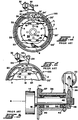
- Brake assembly 100 of FIGURE I is a conventional type brake assembly commonly employed for example for braking a vehicular wheel.
- Assembly 100 has a pair of opposed arcuate brake shoes 4 and 4' respectively comprising support members 6 and 6' that are pivotly mounted at pin 8 at one end and have respective opposed spaced-apart free-ends 10 and 10' at the opposite end.
- rollers 24 and 24' are respectively rotatably mounted at free-ends 10 and 10' of support members 6 and 6' for engagement with the rotary cam member and the words "free-end" as used herein includes such rollers where utilized in the assembly.
- Brake assembly 100 is used to brake generally circular rotary brake drum 2 which includes a central opening 33 in plate 34 thereof for receiving the axle shaft and which is held stationary to the axle by suitable bolts 12. Brake assembly 100 is surrounded by circular rotary brake drum 2 and remains stationary while brake drum 2 rotates about brake shoes 4 and 4'.
- Support members 6 and 6' have respective transverse flanges 22 and 22' to which are respectively secured dual brake lining pads 20 and 20' on the side thereof facing towards brake drum 2.
- Dual brake lining pads 20 and 20' are made from a suitable friction material well known to those skilled in the art of braking rotary brake drum and which are secured to support flanges 22 and 22' by bonding or rivets or other suitable techniques well known to those skilled in the art.
- Assembly 100 includes a conventional rotary "S" shaped cam member 14 well known to those skilled in vehicular brake assembly art.
- Cam member 14 has a central rotational axis "A" shown in FIGURE 3 that is disposed intermediate free-ends 10 and 10' in the brake disengaged condition.
- Cam member 14 is mounted on and is rotated by shaft 16 shown in FIGURES I to 3.
- Rollers 24 and 24' of brake shoes 4 and 4' are respectively urged against opposite sides of cam member 14 by suitable resilient biasing means such as coiled springs 18 having their opposite ends secured to support members 6 and 6' of brake shoes 4 and 4' as shown in FIGURE I.
- Assembly 100 is shown in a brake disengaged condition in FIGURE I and in a brake engaged condition in FIGURE 2.
- FIGURE I here is an initial desired clearance "C” between dual brake lining pads 20 and 20' and brake drum 2 in the brake disengaged condition.
- Rotary cam member 14 is rotated by any suitable means operable to rotate cam member in the rotary direction and angular required to effectively stop drum 2 from rotating upon engagement of the braking by an operator.
- cam member 14 rotates clockwise from a brake disengaged condition in FIGURE I to a brake engaged condition in FIGURE 2. As evident in FIGURE 2, cam member 14 is able to rotate even further in a clockwise direction to make up for wear of brake pads 20 and 20'.
- FIGURES I, 2 and 3 Although suitable mechanical linkages or hydraulic or pneumatic systems may be used to rotate cam member 14 in response to engagement of the brake, a commonly employed pneumatic system is shown in FIGURES I, 2 and 3 for illustrative purposes.
- cam member 14 is secured to one end of shaft 16.
- Shaft 16 is rotatably mounted to housing 36 by spaced-apart bearings 38 which in turn is secured to plate 34 of brake drum 2 by suitable bolts 37. Suitable seals 40 may be included for protecting bearings 38 from contamination.
- the opposite end of shaft 16 contains splines 42 to which one end of eccentric crank arm 28 is secured and held axially by suitable means such as "C" clip 46.
- the opposite end of arm 28 is pivotly connected to rod 30 which is caused to move reciprocally by pneumatic bellows 32 shown in FIGURES I and 2.
- Cam member 14 shown in greater detail in FIGURE 4A, is of the conventional type hereinbefore used having a generally disc shaped transverse cross-section at any point as shown in FIGURE 3.
- Cam member 14 has a pair of diametrically opposed arms 48 and 50 which respectively spiral in the same rotational direction outwardly away from central rotational axis "A" of cam member 14 and shaft 16 to respective peripheral ends 56 and 58.
- Arms 48 and 50 are oriented and are provided with respective diametrically opposed convex curved surfaces 52 and 54 facing in the same rotational direction that are adapted to respectively engage rollers 24 and 24' of free-ends 10 and 10' of support member 6 and 6' and to move brake shoes 4 and 4' away from each other the required distance upon engagement of the brake.
- the minimum breadth of width of cam member 14 in a distance "R” of contact between cam member 14 bridging rotational axis "A” and rollers 24 and 24' is determinative of thickness "Ti", of brake pads 20 and 20 ' as shown in FIGURE I when the brakes are in a disengaged condition.
- the minimum breadth of cam member 14 at axis "A” is represented by the distance 2d i , which is relatively large due to the disc shaped construction heretofore historically used for such "S" shaped cam members.
- the initial maximum thickness T i of brake pads 20 and 20' is generally the maximum distance between the outward facing surfaces of flanges 22 and 22 ' of support members 6 and 6' and brake drum 2 reduced by a desired initial clearance "C' when the brakes are in a disengaged condition with the maximum distance between flanges 22 and 22' and brake drum 2 being a function of the breadth of cam member 14 in the distance "R" of contact hereinbefore described.
- FIGURES 4B and 4C show an embodiment 150 of an improved rotary "S" shaped cam member that is adapted to enable a substantial increase in the thickness of the brake lining pads of assembly 100.
- the breadth of cam member 150 in distance "R” of contact with rollers 24 and 24' bridging rotational axis "A” has been reduced from the conventional disc shaped cross-section to a web shaped configuration such as web 6 shown in section 80-80 of FIGURE 4C having a minimum width 2d 2 at axis "A' that is substantially smaller than width 2d 1 previously described.
- Web 60 has apposed surfaces 63 and 65 which face away from each other and extend outwardly away from axis "A" and merge respectively with initial convex surfaces 52 and 54 at a distance sufficiently inward of peripheral ends 56 and 58 to insure the outward displacements of brake shoes 4 and 4' caused by rotation of cam member 150 remain substantially the same towards the latter part of the braking stroke.
- web 60 includes at least one transverse flange 62 adapted to provide web 60 with strength sufficient for suitable operation of cam member 150 in brake assemblies of the type herein described.
- Web 60 may have flanges 62 and 68 at its opposite edges to provide a "U" type cross section or have a flange 68 without flanges 62.
- web 60 has at least transverse flange 62 as the end thereof spaced apart from shaft 16.
- flange 62 may have any suitable shape provided it imparts web 60 the strength required, flange 62 preferably has an "S" shaped configuration as shown in FIGURE 4B and is preferably integral with web 60.
- Improved rotary "S" shaped cam member 150 is shown disposed intermediate free-ends 10 and 10' of brake shoes 4 and 4 ' of brake assembly 200 in FIGURE 5. It can immediately be seen that providing cam member 150 with a web shaped configuration in distance "R" of contact with free-ends 10 and 10' in the brake disengaged condition has enabled free-ends 10 and 10' (including rollers 24 and 24') to move towards each other by the distance 2d 1 - 2d 2 which in turn has enabled support members 6 and 6 ' to pivot about pin 8 and move towards each other to enable the thickness of frictional brake pads 20 and 20' to be increased to thickness T 2 while maintaining initial clearance "C" between pads 20 and 20' and brake drum 2.
Landscapes
- Engineering & Computer Science (AREA)
- General Engineering & Computer Science (AREA)
- Mechanical Engineering (AREA)
- Braking Arrangements (AREA)
Claims (1)
- Eine Bremsanordnung (200) zum Bremsen einer Drehbremstrommel (2) wobei folgendes vorgesehen ist:zwei entgegengesetzt liegende Bremsschuhe, deren jeder ein einen Bremsbelag (20, 20') tragendes Tragglied (4, 4') und ein Drehnockenglied (150) angeordnet zwischen freien Enden (10, 10') der beiden Tragglieder (4, 4') aufweist, wobei das Nockenglied (150) einen Stegteil (60) und einen Flanschteil (62, 68) umfasst, und zwar in einer Ebene im wesentlichen senkrecht zu dem Stegteil (60) liegend, wobei das Nockenglied (150) entgegengesetzt liegende, konvexe Nockenoberflächen (63, 65) von im ganzen spiralförmiger Gestalt darauf aufweist, welche die freien Enden (10, 10') der Tragglieder (4, 4') auseinander drücken, wenn das Nockenglied (150) aus einer Ruheposition heraus verdreht wird, dadurch gekennzeichnet, daß die Nockenoberfläche (63, 65) ausschließlich auf dem entgegengesetzt liegenden Hauptoberflächen des Stegteil (60) des Nockenglieds (150) liegen, und daß der Flanschteil (62, 68) des Nockenglieds (150) keine Nockenoberfläche trägt.
Applications Claiming Priority (2)
| Application Number | Priority Date | Filing Date | Title |
|---|---|---|---|
| US79181285A | 1985-10-28 | 1985-10-28 | |
| US791812 | 1991-11-13 |
Publications (2)
| Publication Number | Publication Date |
|---|---|
| EP0221750A1 EP0221750A1 (de) | 1987-05-13 |
| EP0221750B1 true EP0221750B1 (de) | 1990-01-31 |
Family
ID=25154862
Family Applications (1)
| Application Number | Title | Priority Date | Filing Date |
|---|---|---|---|
| EP19860308355 Expired EP0221750B1 (de) | 1985-10-28 | 1986-10-27 | Bremsanordnung und drehbarer Nocken dazu |
Country Status (3)
| Country | Link |
|---|---|
| EP (1) | EP0221750B1 (de) |
| CA (1) | CA1277606C (de) |
| DE (1) | DE3668677D1 (de) |
Cited By (1)
| Publication number | Priority date | Publication date | Assignee | Title |
|---|---|---|---|---|
| CN106168261A (zh) * | 2015-05-18 | 2016-11-30 | 阿文美驰技术有限责任公司 | 具有带槽凸轮轴的制动器组件 |
Families Citing this family (2)
| Publication number | Priority date | Publication date | Assignee | Title |
|---|---|---|---|---|
| US5638928A (en) * | 1995-12-07 | 1997-06-17 | Rockwell International Corporation | Brake center tracking roller and cam arrangement |
| US7175009B2 (en) | 2004-07-20 | 2007-02-13 | Bendix Spicer Foundation Brake Llc | Cam actuated drum brake |
Family Cites Families (6)
| Publication number | Priority date | Publication date | Assignee | Title |
|---|---|---|---|---|
| US1865042A (en) * | 1928-12-22 | 1932-06-28 | George E Pellissier | Brake for motor vehicles |
| US3497037A (en) * | 1968-03-08 | 1970-02-24 | Eaton Yale & Towne | Stop mechanism for a cam brake |
| GB1306229A (de) * | 1969-05-20 | 1973-02-07 | ||
| GB1281746A (en) * | 1969-08-13 | 1972-07-12 | Fruehauf Corp | Expanding mechanism for internal shoe drum brakes |
| SE368611B (de) * | 1972-03-22 | 1974-07-08 | Linde Int Ab | |
| GB1589002A (en) * | 1978-04-26 | 1981-05-07 | Magyar Vagon Es Gepgyar | Expander for internal shoe drum brakes |
-
1986
- 1986-10-17 CA CA000520739A patent/CA1277606C/en not_active Expired - Lifetime
- 1986-10-27 EP EP19860308355 patent/EP0221750B1/de not_active Expired
- 1986-10-27 DE DE8686308355T patent/DE3668677D1/de not_active Expired - Lifetime
Cited By (1)
| Publication number | Priority date | Publication date | Assignee | Title |
|---|---|---|---|---|
| CN106168261A (zh) * | 2015-05-18 | 2016-11-30 | 阿文美驰技术有限责任公司 | 具有带槽凸轮轴的制动器组件 |
Also Published As
| Publication number | Publication date |
|---|---|
| EP0221750A1 (de) | 1987-05-13 |
| DE3668677D1 (de) | 1990-03-08 |
| CA1277606C (en) | 1990-12-11 |
Similar Documents
| Publication | Publication Date | Title |
|---|---|---|
| US4044864A (en) | Disc brake | |
| US4256209A (en) | Axially displaceable brake disc | |
| EP0258625B1 (de) | S-Nocken für Trommelbremse | |
| US20080099174A1 (en) | Brake caliper | |
| US5947234A (en) | Disc brake | |
| US4476968A (en) | Expanding shoe drum brake | |
| US20040222053A1 (en) | Pad retraction spring for a brake shoe assembly and a disc brake assembly | |
| US3917032A (en) | Single mount and guide pin for a caliper of a disc brake assembly | |
| KR100471910B1 (ko) | 일체형 주차브레이크를 갖는 다중 디스크 브레이크장치 | |
| US6520296B1 (en) | Multiple disc brake system | |
| CA2023237C (en) | Brake having anchor bearing on spider | |
| EP0145977B1 (de) | Scheibenbremse entgegengesetzt schwingbare Zylinder und Bremssattel aufweisend | |
| US6189659B1 (en) | Disk brake | |
| JPH11513468A (ja) | 車両用ディスクブレーキ装置 | |
| US4353442A (en) | Brake shoe and brake assembly for automotive vehicles | |
| EP0221750B1 (de) | Bremsanordnung und drehbarer Nocken dazu | |
| EP0816706A2 (de) | Bimodale Trommelbremse mit einem Feststellbremshebel, der um eine zur Bremsträgerplatte senkrecht stehende Achse dreht | |
| US3998296A (en) | Anti-rattle spring for a motor vehicle disc brake | |
| US3780835A (en) | Disc brakes for vehicles | |
| US2873005A (en) | Disc brake for vehicles | |
| CA1076494A (en) | Brake assembly | |
| US4039054A (en) | Disc brakes for vehicles | |
| EP1321690A1 (de) | Trommelbremse mit bremsschuh mit mehreren freiheitsgraden | |
| JPS5917292B2 (ja) | 摺動キヤリパデイスクブレ−キ | |
| US4480725A (en) | Spot type brake with floating caliper |
Legal Events
| Date | Code | Title | Description |
|---|---|---|---|
| PUAI | Public reference made under article 153(3) epc to a published international application that has entered the european phase |
Free format text: ORIGINAL CODE: 0009012 |
|
| AK | Designated contracting states |
Kind code of ref document: A1 Designated state(s): DE FR GB |
|
| 17P | Request for examination filed |
Effective date: 19870619 |
|
| 17Q | First examination report despatched |
Effective date: 19880506 |
|
| GRAA | (expected) grant |
Free format text: ORIGINAL CODE: 0009210 |
|
| AK | Designated contracting states |
Kind code of ref document: B1 Designated state(s): DE FR GB |
|
| REF | Corresponds to: |
Ref document number: 3668677 Country of ref document: DE Date of ref document: 19900308 |
|
| ET | Fr: translation filed | ||
| PLBI | Opposition filed |
Free format text: ORIGINAL CODE: 0009260 |
|
| 26 | Opposition filed |
Opponent name: BERGISCHE ACHSENFABRIK FR. KOTZ & SOEHNE Effective date: 19900905 |
|
| PLAB | Opposition data, opponent's data or that of the opponent's representative modified |
Free format text: ORIGINAL CODE: 0009299OPPO |
|
| R26 | Opposition filed (corrected) |
Opponent name: BERGISCHE ACHSENFABRIK FR. KOTZ & SOEHNE Effective date: 19900905 |
|
| PGFP | Annual fee paid to national office [announced via postgrant information from national office to epo] |
Ref country code: GB Payment date: 19910926 Year of fee payment: 6 |
|
| PGFP | Annual fee paid to national office [announced via postgrant information from national office to epo] |
Ref country code: FR Payment date: 19911021 Year of fee payment: 6 |
|
| PGFP | Annual fee paid to national office [announced via postgrant information from national office to epo] |
Ref country code: DE Payment date: 19911030 Year of fee payment: 6 |
|
| RDAG | Patent revoked |
Free format text: ORIGINAL CODE: 0009271 |
|
| STAA | Information on the status of an ep patent application or granted ep patent |
Free format text: STATUS: PATENT REVOKED |
|
| 27W | Patent revoked |
Effective date: 19920424 |
|
| GBPR | Gb: patent revoked under art. 102 of the ep convention designating the uk as contracting state |