EP0221730A1 - Abrasive entrained high pressure fluid jet apparatus and method of use - Google Patents
Abrasive entrained high pressure fluid jet apparatus and method of use Download PDFInfo
- Publication number
- EP0221730A1 EP0221730A1 EP86308228A EP86308228A EP0221730A1 EP 0221730 A1 EP0221730 A1 EP 0221730A1 EP 86308228 A EP86308228 A EP 86308228A EP 86308228 A EP86308228 A EP 86308228A EP 0221730 A1 EP0221730 A1 EP 0221730A1
- Authority
- EP
- European Patent Office
- Prior art keywords
- concrete
- high pressure
- rock
- pressure fluid
- cutting
- Prior art date
- Legal status (The legal status is an assumption and is not a legal conclusion. Google has not performed a legal analysis and makes no representation as to the accuracy of the status listed.)
- Withdrawn
Links
Images


Classifications
-
- B—PERFORMING OPERATIONS; TRANSPORTING
- B26—HAND CUTTING TOOLS; CUTTING; SEVERING
- B26F—PERFORATING; PUNCHING; CUTTING-OUT; STAMPING-OUT; SEVERING BY MEANS OTHER THAN CUTTING
- B26F3/00—Severing by means other than cutting; Apparatus therefor
-
- B—PERFORMING OPERATIONS; TRANSPORTING
- B28—WORKING CEMENT, CLAY, OR STONE
- B28D—WORKING STONE OR STONE-LIKE MATERIALS
- B28D1/00—Working stone or stone-like materials, e.g. brick, concrete or glass, not provided for elsewhere; Machines, devices, tools therefor
Definitions
- This invention relates in general to an apparatus and method for cutting and breaking rock, concrete and other high strength materials, and in particular to an abrasive entrained high pressure fluid jet cutting apparatus for cutting and breaking rock, concrete and other high strength materials having a greater compressive strength than tensile strength.
- materials such as rock, ore, coal, concrete and asphalt
- mechanical tools which cause fractures by overcoming the compressive strength, impact resistance, or shear strength of the materials involved.
- asphalt and concrete pavements are usually fractured today by pneumatic, hydraulic or drop weight hammers.
- Rotary cutters are widely used to shear off coal.
- Pneumatic or hydraulic impactors are used to break up rock and ores.
- Rotary or percussive drills are used today for drilling holes in rock.
- High pressure waterjets pulsed or continuous, have found use in cutting, slitting, and breaking porous and/or brittle materials such as rock and concrete.
- the waterjet processes have many advantages over existing mechanical techniques in the areas of efficiency, noise generation, dust generation, tool wear, vibration and shocks.
- Pulsed waterjets can be particularly effective in fracturing rock, ores, concrete and other brittle materials, by overcoming the tensile strength of the materials instead of the compressive strength dealt with by the conventional mechanical techniques. Since the tensile strength of the cited materials is considerably lower than their respective compressive strength, the energy required to fracture these materials with waterjets is therefore, comparatively lower.
- the depth of hole drilled by the fluid must be sufficiently deep if a large amount of material is to be fractured with one pulse.
- To drill such a deep hole in hard rock and concrete requires a substantial amount of fluid energy.
- the pulsed jet generator must be so large that its use in the field, particularly in urban areas, becomes troublesome and impractical.
- a size reduction of pulsed waterjet devices without sacrificing capabilities has not been successful to date.
- the difficulty in devising a compact pulsed waterjet device for breaking concrete or rock is related to the fluid power required to drill a hole of sufficient depth; relatively little power is required to generate hoop stresses inside the hole once it is made. Drilling holes in hard concrete and rock with fluid jets is not an easy task.
- the present invention is an abrasive entrained high pressure fluid jet apparatus having a first smaller biasing means for maintaining the abrasive entrained high pressure fluid jet apparatus at a perdetermined distance away from material to be cut or broken and a receiving means for receiving an operator executed larger second bias in the opposite direction.
- the method of the invention includes cutting a pilot hole within rock, concrete, or other material to a predetermined depth less than the depth of said material, shutting off the source of abrasive granules to the high pressure fluid jet apparatus and building up pressure within said pilot hole in excess of the tensile strength of the material.
- Abrasive entrained high pressure fluid jet hammer apparatus 10 includes rigid cylindrical conduit 12 for passing pressurized water from an external source (not shown) through a flexible hose 14 to nozzle 16.
- Nozzle 16 is described in detail in concurrently filed our European patent application No. ........, (Representatives reference no. 28181) entitled “Abrasive Entrained High Pressure Fluid Jet Nozzle” and filed on the same day as the present application.
- Nozzle 16 is a novel high pressure fluid jet nozzle having a means for generating a predetermined pattern of high pressure fluid streams to entrain abrasive granules within the interior of the predetermined pattern of high pressure fluid streams to prevent wear of the exit orifice of the nozzle.
- Nozzle 16 further includes a valve means for preventing wetting and caking of the abrasive granules in the vicinity of the predetermined pattern of high pressure fluid streams.
- abrasive entrained high pressure fluid jet hammer apparatus 10 further includes a hand operated high pressure fluid supply valve 18 to control the flow of high pressure fluid, a nozzle shroud 22 enveloping nozzle 16, support frame 24 in rigid communication with shroud 22, and support means 26 in rigid communication with support frame 24, which may be, for example as shown in the preferred embodiment, axle 32 and support wheel 34.
- Abrasive entrained high pressure fluid jet hammer apparatus 10 further includes first smaller biasing means 42, which may be for example the helical spring shown in the preferred embodiment, disposed between cylindrical conduit and nozzle combination 52 and support frame 24 for biasing cylindrical conduit/nozzle combination 52 in the upward direction and receiving means 62 which may be for example the shoulder support shown in the preferred embodiment for receiving a second larger bias such as for example the weight of an operator in the downward direction so as to overcome first biasing means 42.
- first smaller biasing means 42 which may be for example the helical spring shown in the preferred embodiment, disposed between cylindrical conduit and nozzle combination 52 and support frame 24 for biasing cylindrical conduit/nozzle combination 52 in the upward direction
- receiving means 62 which may be for example the shoulder support shown in the preferred embodiment for receiving a second larger bias such as for example the weight of an operator in the downward direction so as to overcome first biasing means 42.
- High pressure fluid jet hammer apparatus 10 further includes handle bar 64 adjustably mounted around the middle of cylindrical conduit 12, abrasive hose 66 for transporting abrasive granules from an external reservoir (not shown) to nozzle 16 and hand lever 68 and cable 72 for operating the abrasive granule valve means of nozzle 16 as described in the above referenced European patent application.
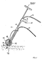
- Figure 1 illustrates the position of high pressure fluid jet hammer apparatus 10 at a predetermined angle from the vertical position (approximately 30 degrees) for applying an abrasive entrained waterjet to cut concrete, rock or other high strength material such as the concrete material 78 shown.
- Figure 2 illustrates high pressure fluid jet hammer apparatus 10 in the vertical position having a large biasing means such as the operator's weight overcoming biasing means 42 to position nozzle 16 and nozzle tip 82 vertically against the entrance to a cut pilot hole 84 within the concrete material 78 for applying the breaking mode of the novel method for breaking concrete according to the teachings of the invention.
- High pressure fluid jet hammer apparatus 10 is pushed to overcome first biasing means 42 and shroud 22 is buffeted against the concrete material 78.
- the tip 82 of nozzle 16 is compressed against the entrance 84 of pilot hole 82 by the bias force of the operator's weight, thus hindering the escape of fluid trapped inside the hole and enhancing the buildup of fluid pressure inside the hole to cause fracturing of the surrounding high strength material.
- Equipment system 100 consists of a suitable pump system 102 such as for example a triplex crankshift pump 104 capable of delivering water at a peak pressure of up to 20,000 psi in rotating communication with an engine or motor shown generally at 106 which may be for instance a diesel engine or an electric motor of suitable power rating and an abrasive feed and dispensing system 108.
- a suitable pump system 102 such as for example a triplex crankshift pump 104 capable of delivering water at a peak pressure of up to 20,000 psi in rotating communication with an engine or motor shown generally at 106 which may be for instance a diesel engine or an electric motor of suitable power rating and an abrasive feed and dispensing system 108.
- Both high pressure pump 102 and abrasive systems 108 are connected to high pressure flow jet hammer apparatus 10 through suitable high pressure fluid hose 112 and abrasive hose 114, respectively.
- Feed water, or other suitable fluid is fed to pump system 102 through filter 122 to remove particulates.
- the pressurized water is transported to water hammer apparatus 10 via high pressure hose 112 through by-pass valve 124 and pressure regulating means 126, by-pass valve 124 having a return connection through by-pass conduit 128 to pump system 102.
- Flexible hoses are currently available for system pressures of 20,000 psi, rigid metallic tubing being required if the system pressure is substantially higher than 20,000 psi.
- abrasives which could be sand, garnet, metallic slag or other industrial abrasives, are stored in a metallic abrasive tank 132.
- the abrasives are urged through abrasive hose 114 by means of the vacuum generated inside the nozzle of the high pressure hammer apparatus 10 by the high speed fluid jets (not shown but described in detail in the above-referenced, concurrently filed, co-pending application No. ........, reference as 28181
- This suction power can be as high as 20 to 30 inches of mercury and is powerful enough to bring heavy abrasives from a distant tank to the nozzle without the need for an external power supply, For excessively long distance or excessively heavy abrasives, however, an external supply of compressed air can be used.
- Valve means 134 is attached to abrasive tank 132 to adjust a desired flow rate.
- garnet abrasives can cut high strength concrete to a depth greater than 6 inches when the nozzle is moved along the surface of the pavement at a speed of about 6 inches per minute using the nominal orifice nozzle of this invention as described in the above referenced European patent application.
- the cut or slot using high pressure hammer apparatus 10 is typically very clean and substantially straight; spalling of concrete or aggregate is rarely encountered.
- the apparatus is held by an operator with one hand holding the water valve handle and operating the water valve actuating lever 28, while the other hand is holding the handle 64 and operating abrasive valve actuating lever 68.
- the shoulder support of the apparatus is butted against the operators shoulder or upper arm to thereby provide the downward bias discussed earlier.
- the abrasive fluid jet nozzle is positioned very close to the surface of the pavement, the stand off distance between the pavement and the nozzle is maintained by the support means 26 which may be for example support wheel 24 and is adjustable. It is desired that the water hammer apparatus is held and operated at an angle of about 70 to 80 degrees to the pavement surface and is advanced with the fluid jet leading the nozzle as shown in Figure 3.
- the high pressure fluid hammer apparatus of this invention can be used with the fluid jet trailing the nozzle or at a vertical position.
- the difference in cutting performance does not deviate much if the impingement angle is changed within a predetermined range of +/- 30°.
- the depth of cut can be adjusted by changing one of several system parameters, including system pressure, abrasive type and/or feed rate, nozzle stand off distance and nozzle traverse speed. This built in system flexibility is unmatched by any conventional material cutting methods.
- a patch of pavement In many pavement cutting operations, a patch of pavement must be removed to gain access to the soil and to buried systems such as cables and pipes.
- the apparatus of this invention can be used to make the perimeter cuts that delineate the area to be removed. The cuts may be through the entire thickness of the pavement such that the cut pads could be lifted with a suitable anchor system.
- a patch of concrete to be removed is outlined by perimeter cuts made with the abrasive entrained high pressure fluid jet hammer apparatus of the invention.
- To break this patch of concrete with the fluid hammer of the invention involves drilling partial depth holes by applying the abrasive water jet at a stationary position for a perscribed amount of time, such as 10 seconds or less, and by shutting off the abrasive supply after a hole of desired depth has been achieved.
- the cessation of abrasive flow stops the drilling operation as a water jet alone cannot drill concrete rapidly at water pressures of 20,000 psi or less.
- the operator would then use the receiving means for receiving the bias of his weight on the high pressure fluid jet hammer apparatus 10 to overcome the bias of the smaller first biasing means to insert the nozzle tip within the pilot hole as discussed earlier.
- the perimeter cuts should also be made to a partial depth.
- the reason is to avoid water jet penetration into the soil or underlying material to wash away pavement support.
- the water can be readily syphoned away with a suction system if it is kept on the surface of the pavement. This way only the water that was consumed in the breaking of the pavement would be lost into the subsoil.
- the efficiency of the breaking operation of the process of this invention is related to the force applied to the apparatus to keep the tip of the nozzle on top of the hole and how well the tip fits the hole. This explains why the tip of the nozzle cone should be convexly tapered externally.
- the amount of taper and the outside diameter of the nozzle cone are determined basically by the configuration of the waterjet bundle issued by the orifices.
- the significant advantages of this process as compared to existing methods of using jackhammers to break concrete are as follows: * Much higher productivity as each shot can remove substantially large amounts of concrete * No shock to underlying structures or to the operator * A single tool for cutting and breaking.
- the process of this invention involves the creation of pilot holes with abrasive-entrained waterjet, cutting slots with the same abrasive-entrained waterjet, and breaking concrete or rock with straight waterjet by generating high loop stresses inside the pilot holes.
- the suitable apparatus for applying this process could be the handheld device described herein; it could also be in the form of a mounted device.
Abstract
For breaking and cutting a material having greater compressive than tensile strength, such as concrete, high pressure water from a hose (14) passes through a shaft (12) to a nozzle (16) where it entrains abrasive granules from a hose (66) also connected to the nozzle (16). The upper end of the shaft (12) has a shoulder support for pressure downwards, and the lower end has a support frame (24) with a support wheel (34) which runs over the surface of the material to be broken and cut. A spring (42) biases the shaft (12) and nozzle (16) combination upwardly from the support frame (24) to which a shroud (22) surrounding the nozzle is attached. A pilot hole (84) is cut first, then the tip (82) of the nozzle (16) is pressed sealingly against the mouth (84) of the hole (82) so that fluid pressure built up in the hole (82) fractures the surrounding material.
Description
- This invention relates in general to an apparatus and method for cutting and breaking rock, concrete and other high strength materials, and in particular to an abrasive entrained high pressure fluid jet cutting apparatus for cutting and breaking rock, concrete and other high strength materials having a greater compressive strength than tensile strength.
- In mining and demolition, it is necessary to fracture hard materials including coals, ores, rocks and concrete. Further, in repairing roads and bridges, deteriorated concrete must be removed prior to laying a fresh layer of concrete. Many utility systems in urban areas are installed beneath steet pavements and require frequent breaking of the pavement for purpose of installation and repair.
- Currently, materials such as rock, ore, coal, concrete and asphalt, are commonly fractured with mechanical tools which cause fractures by overcoming the compressive strength, impact resistance, or shear strength of the materials involved. For example, asphalt and concrete pavements are usually fractured today by pneumatic, hydraulic or drop weight hammers. Rotary cutters are widely used to shear off coal. Pneumatic or hydraulic impactors are used to break up rock and ores. Rotary or percussive drills are used today for drilling holes in rock.
- Since these conventional tools all function on impacting or shearing the materials with a mechanical cutter, impactor, or moil, they have some common problems. These problems included wear and tear of the tool, generation of dust, generation of noise and shock, and lack of efficiency. Consequently, efforts have been directed toward the development of improved techniques and equipment for breaking hard and brittle minerals.
- High pressure waterjets, pulsed or continuous, have found use in cutting, slitting, and breaking porous and/or brittle materials such as rock and concrete. The waterjet processes have many advantages over existing mechanical techniques in the areas of efficiency, noise generation, dust generation, tool wear, vibration and shocks. Pulsed waterjets can be particularly effective in fracturing rock, ores, concrete and other brittle materials, by overcoming the tensile strength of the materials instead of the compressive strength dealt with by the conventional mechanical techniques. Since the tensile strength of the cited materials is considerably lower than their respective compressive strength, the energy required to fracture these materials with waterjets is therefore, comparatively lower.
- An apparatus and process based on the pressure extrusion technique for producing high velocity waterjet pulses for fracturing rocks and concrete is in U.S. Patent No. 4,074,858. Suitable thrust-generators for use with the high pressure waterjet apparatus as disclosed in U.S. Patent No. 4,074,858 have been described in the U.S. Patent Nos. 3,999,384 and 4,052,850. A more advanced high pressure pulsed waterjet generator is described in the U.S. Patent No. 4,190,202. These patents indicate that concrete and rocks can be readily fractured if the waterjet can drill a deep hole in such materials and have sufficient fluid energy left to build up pressure inside the hole. The depth of hole drilled by the fluid must be sufficiently deep if a large amount of material is to be fractured with one pulse. To drill such a deep hole in hard rock and concrete requires a substantial amount of fluid energy. As a result, the pulsed jet generator must be so large that its use in the field, particularly in urban areas, becomes troublesome and impractical. A size reduction of pulsed waterjet devices without sacrificing capabilities has not been successful to date. The difficulty in devising a compact pulsed waterjet device for breaking concrete or rock is related to the fluid power required to drill a hole of sufficient depth; relatively little power is required to generate hoop stresses inside the hole once it is made. Drilling holes in hard concrete and rock with fluid jets is not an easy task. It has been known that a certain amount of fluid energy, which is translated in waterjet terms as pressure and flow rate, is required to remove a given amount of concrete or rock. This energy requirement is also called the specific energy for material removal. The harder the concrete or rock, the greater the fluid energy that is required. To drill a small hole of useful depth in concrete, such as 6 to 8 inches, is known to require a high level of fluid energy that a compact pulsed waterjet generator simply cannot provide. In fact, the requirement of high specific energy is the basic reason why high-pressure waterjets have not found practical applications in cutting, slotting or drilling hard concrete and rocks. The ability of high-pressure waterjets in removing hard materials can be drastically improved if abrasives could be incorporated into the waterjets. However, this is difficult to implement without sacrificing the waterjet's quality as coherence of waterjets and abrasive entrainment are conflicting issues. Thus, this known idea of adding abrasives into waterjets has had limited success as a useful process; existing pro- cesses are useful for cleaning metals but cannot cut hard materials. Accordingly, it would be desirable to have a means and method for breaking and cutting rock, concrete and other high strength materials by the use of abrasive entrained high pressure fluid jet apparatus for overcoming the tensile strength of said materials rather than their compressive strength.
- Briefly the present invention is an abrasive entrained high pressure fluid jet apparatus having a first smaller biasing means for maintaining the abrasive entrained high pressure fluid jet apparatus at a perdetermined distance away from material to be cut or broken and a receiving means for receiving an operator executed larger second bias in the opposite direction. The method of the invention includes cutting a pilot hole within rock, concrete, or other material to a predetermined depth less than the depth of said material, shutting off the source of abrasive granules to the high pressure fluid jet apparatus and building up pressure within said pilot hole in excess of the tensile strength of the material.
- The invention may be better understood and further advantages and uses thereof more readily apparent by means of the following detailed description of exemplary embodiments, taken in connection with the following drawings, in which:
- Figure 1 is a side elevational view of a hand held abrasive entrained fluid jet hammer apparatus, constructed according to the teachings of the invention, illustrating the support means and first smaller biasing means for biasing the high pressure conduit and nozzle combination in a first predetermined direction and the receiving means for the application of a second larger bias in the opposite direction;
- Figure 2 is a front elevational view of the hand held abrasive entrained high pressure fluid jet hammer apparatus of Figure 1;
- Figure 3 is a schematic view illustrating the major components of an abrasive entrained high pressure fluid jet hammer apparatus including the high pressure fluid pumping station and an abrasive granular feed station;
- Figure 4 is a cross-sectional view of typical concrete material illustrating a method for breaking high strength material according to the teachings of the invention; and
- Figure 5 is a top view of the concrete material of Figure 4 illustrating the placement of pilot holes according to the method of the invention for breaking high strength materials.
- Referring now to the drawings and to Figure 1, in particular there is shown a side elevational view of a hand held abrasive entrained high pressure fluid hammer apparatus for applying an abrasive waterjet to cut or break rock and concrete. Abrasive entrained high pressure fluid jet hammer apparatus 10 includes rigid
cylindrical conduit 12 for passing pressurized water from an external source (not shown) through aflexible hose 14 tonozzle 16. Nozzle 16 is described in detail in concurrently filed our European patent application No. ........, (Representatives reference no. 28181) entitled "Abrasive Entrained High Pressure Fluid Jet Nozzle" and filed on the same day as the present application. - Nozzle 16 is a novel high pressure fluid jet nozzle having a means for generating a predetermined pattern of high pressure fluid streams to entrain abrasive granules within the interior of the predetermined pattern of high pressure fluid streams to prevent wear of the exit orifice of the nozzle.
Nozzle 16 further includes a valve means for preventing wetting and caking of the abrasive granules in the vicinity of the predetermined pattern of high pressure fluid streams. - Referring now to Figures 1 and 2, abrasive entrained high pressure fluid jet hammer apparatus 10 further includes a hand operated high pressure
fluid supply valve 18 to control the flow of high pressure fluid, anozzle shroud 22 envelopingnozzle 16,support frame 24 in rigid communication withshroud 22, and support means 26 in rigid communication withsupport frame 24, which may be, for example as shown in the preferred embodiment,axle 32 andsupport wheel 34. Abrasive entrained high pressure fluid jet hammer apparatus 10 further includes first smaller biasing means 42, which may be for example the helical spring shown in the preferred embodiment, disposed between cylindrical conduit andnozzle combination 52 andsupport frame 24 for biasing cylindrical conduit/nozzle combination 52 in the upward direction and receivingmeans 62 which may be for example the shoulder support shown in the preferred embodiment for receiving a second larger bias such as for example the weight of an operator in the downward direction so as to overcome first biasing means 42. High pressure fluid jet hammer apparatus 10 further includeshandle bar 64 adjustably mounted around the middle ofcylindrical conduit 12,abrasive hose 66 for transporting abrasive granules from an external reservoir (not shown) tonozzle 16 andhand lever 68 andcable 72 for operating the abrasive granule valve means ofnozzle 16 as described in the above referenced European patent application. - Figure 1 illustrates the position of high pressure fluid jet hammer apparatus 10 at a predetermined angle from the vertical position (approximately 30 degrees) for applying an abrasive entrained waterjet to cut concrete, rock or other high strength material such as the
concrete material 78 shown. Figure 2 illustrates high pressure fluid jet hammer apparatus 10 in the vertical position having a large biasing means such as the operator's weight overcoming biasing means 42 to positionnozzle 16 andnozzle tip 82 vertically against the entrance to a cut pilot hole 84 within theconcrete material 78 for applying the breaking mode of the novel method for breaking concrete according to the teachings of the invention. High pressure fluid jet hammer apparatus 10 is pushed to overcome first biasing means 42 andshroud 22 is buffeted against theconcrete material 78. Thetip 82 ofnozzle 16 is compressed against the entrance 84 ofpilot hole 82 by the bias force of the operator's weight, thus hindering the escape of fluid trapped inside the hole and enhancing the buildup of fluid pressure inside the hole to cause fracturing of the surrounding high strength material. - Referring now to Figure 3 there is shown a schematic view of the equipment system that can be used with the abrasive entrained high pressure fluid jet hammer apparatus of the invention to drill, cut or slot concrete, asphalt, pavement, rock and other high strength materials.
Equipment system 100 consists of asuitable pump system 102 such as for example atriplex crankshift pump 104 capable of delivering water at a peak pressure of up to 20,000 psi in rotating communication with an engine or motor shown generally at 106 which may be for instance a diesel engine or an electric motor of suitable power rating and an abrasive feed and dispensingsystem 108. Bothhigh pressure pump 102 andabrasive systems 108 are connected to high pressure flow jet hammer apparatus 10 through suitable high pressurefluid hose 112 andabrasive hose 114, respectively. Feed water, or other suitable fluid, is fed to pumpsystem 102 through filter 122 to remove particulates. After going throughcrankshaft pump 104 the pressurized water is transported to water hammer apparatus 10 viahigh pressure hose 112 through by-pass valve 124 and pressure regulating means 126, by-pass valve 124 having a return connection through by-pass conduit 128 to pumpsystem 102. Flexible hoses are currently available for system pressures of 20,000 psi, rigid metallic tubing being required if the system pressure is substantially higher than 20,000 psi. - Referring again now to Figure 3, selected abrasives, which could be sand, garnet, metallic slag or other industrial abrasives, are stored in a metallic
abrasive tank 132. The abrasives are urged throughabrasive hose 114 by means of the vacuum generated inside the nozzle of the high pressure hammer apparatus 10 by the high speed fluid jets (not shown but described in detail in the above-referenced, concurrently filed, co-pending application No. ........, reference as 28181 - This suction power can be as high as 20 to 30 inches of mercury and is powerful enough to bring heavy abrasives from a distant tank to the nozzle without the need for an external power supply, For excessively long distance or excessively heavy abrasives, however, an external supply of compressed air can be used. Valve means 134 is attached to
abrasive tank 132 to adjust a desired flow rate. - For cutting concrete and asphalt pavement, a sharp glacial sand and garnet have been found to be particularly effective. At feed rates of about 1 to 2 lbs. per minute in water pressures of 20,000 psi, garnet abrasives can cut high strength concrete to a depth greater than 6 inches when the nozzle is moved along the surface of the pavement at a speed of about 6 inches per minute using the nominal orifice nozzle of this invention as described in the above referenced European patent application. The cut or slot using high pressure hammer apparatus 10 is typically very clean and substantially straight; spalling of concrete or aggregate is rarely encountered.
- Referring now to Figures 1, 2, and 3, during the cutting operation, the apparatus is held by an operator with one hand holding the water valve handle and operating the water
valve actuating lever 28, while the other hand is holding thehandle 64 and operating abrasivevalve actuating lever 68. The shoulder support of the apparatus is butted against the operators shoulder or upper arm to thereby provide the downward bias discussed earlier. The abrasive fluid jet nozzle is positioned very close to the surface of the pavement, the stand off distance between the pavement and the nozzle is maintained by the support means 26 which may be forexample support wheel 24 and is adjustable. It is desired that the water hammer apparatus is held and operated at an angle of about 70 to 80 degrees to the pavement surface and is advanced with the fluid jet leading the nozzle as shown in Figure 3. However, the high pressure fluid hammer apparatus of this invention can be used with the fluid jet trailing the nozzle or at a vertical position. The difference in cutting performance does not deviate much if the impingement angle is changed within a predetermined range of +/- 30°. The depth of cut can be adjusted by changing one of several system parameters, including system pressure, abrasive type and/or feed rate, nozzle stand off distance and nozzle traverse speed. This built in system flexibility is unmatched by any conventional material cutting methods. - In many pavement cutting operations, a patch of pavement must be removed to gain access to the soil and to buried systems such as cables and pipes. In such operations, the apparatus of this invention can be used to make the perimeter cuts that delineate the area to be removed. The cuts may be through the entire thickness of the pavement such that the cut pads could be lifted with a suitable anchor system. Referring now to Figure 4, a patch of concrete to be removed is outlined by perimeter cuts made with the abrasive entrained high pressure fluid jet hammer apparatus of the invention. To break this patch of concrete with the fluid hammer of the invention involves drilling partial depth holes by applying the abrasive water jet at a stationary position for a perscribed amount of time, such as 10 seconds or less, and by shutting off the abrasive supply after a hole of desired depth has been achieved. The cessation of abrasive flow stops the drilling operation as a water jet alone cannot drill concrete rapidly at water pressures of 20,000 psi or less. The operator would then use the receiving means for receiving the bias of his weight on the high pressure fluid jet hammer apparatus 10 to overcome the bias of the smaller first biasing means to insert the nozzle tip within the pilot hole as discussed earlier. At this point, high hoop stresses are generated in the concrete around the hole, thus causing tensile failures as the tensile strength of concrete is considerably lower than its compressive strength. When the holes are of suitable depth in reference to the thickness of the slab involved and are properly spaced in relationship to each other and to the available free edges, the entire patch can be broken with a minimum number of shots as illustrated in Figure 5 at
numbers 201 through 205 inclusive. The exact spacing of these pilot holes to each other and to the perimeter are governed by several factors, including the system perimeters and the concrete strength. It should be noted that the pilot holes must not be drilled through the entire thickness of the concrete as pressure cannot be built inside the hole as the waterjet would simply be ejected to the underlying soil or material. In many applications the perimeter cuts should also be made to a partial depth. The reason is to avoid water jet penetration into the soil or underlying material to wash away pavement support. The water can be readily syphoned away with a suction system if it is kept on the surface of the pavement. This way only the water that was consumed in the breaking of the pavement would be lost into the subsoil. - The efficiency of the breaking operation of the process of this invention is related to the force applied to the apparatus to keep the tip of the nozzle on top of the hole and how well the tip fits the hole. This explains why the tip of the nozzle cone should be convexly tapered externally. The amount of taper and the outside diameter of the nozzle cone are determined basically by the configuration of the waterjet bundle issued by the orifices. The significant advantages of this process as compared to existing methods of using jackhammers to break concrete are as follows:
* Much higher productivity as each shot can remove substantially
large amounts of concrete
* No shock to underlying structures or to the operator
* A single tool for cutting and breaking. - In conclusion, what has been disclosed is a novel and useful method for cutting, breaking and removing concrete, rock, and other brittle materials. The process of this invention involves the creation of pilot holes with abrasive-entrained waterjet, cutting slots with the same abrasive-entrained waterjet, and breaking concrete or rock with straight waterjet by generating high loop stresses inside the pilot holes. The suitable apparatus for applying this process could be the handheld device described herein; it could also be in the form of a mounted device.
Claims (5)
1. An abrasive entrained fluid jet hammer apparatus for cutting and breaking rock and concrete, comprising;
a) a high pressure fluid nozzle in fluid communication with and rigidly attached at one end to a high pressure fluid shaft;
b) a frame having a support shroud circumventing said high pressure fluid shaft and high pressure fluid nozzle combination;
c) a first biasing means disposed between said support shroud and said high pressure fluid shaft and high pressure fluid nozzle combination for biasing said high pressure fluid jet nozzle and high pressure shaft combination within said frame shroud in a direction away from the work piece;
d) means for moving said high pressure fluid jet hammer apparatus along the surface of said rock and concrete; and
e) biasing support in rigid communication at a predetermined location along said high pressure fluid shaft for receiving a second biasing means operating in the opposite direction of said first biasing means.
2. A method for cutting and breaking rock, concrete and other high strength materials, by means of an abrasive entrained fluid jet hammer apparatus, comprising;
a) First cutting a pilot hole to a predetermined depth within said rock, concrete or other high strength material, by means of an abrasive entrained high pressure fluid jet stream of a predetermined configuration;
b) shutting off the abrasive granules to the high pressure fluid jet stream while biasing said abrasive entrained fluid jet hammer apparatus against said pilot hole to build up fluid pressure within said pilot hole to generate hoop stress within said rock, concrete, or other high strength material of a sufficient magnitude to break said rock, concrete, or other high strength material.
3. The method of claim 2 for cutting and breaking rock, concrete and other high strength materials further including the step of cutting a slot in the rock, concrete, and other high strength materials prior to step b) shutting off the abrasive granules to the high pressure fluid jet stream while biasing said abrasive entrained fluid jet hammer apparatus against said pilot hole to build up fluid pressure within said pilot hole to generate hoop stress within said rock, concrete, or other high strength material of a sufficient magmitude to break said rock, concrete, or other high strength material.
4. The method of claim 3 wherein the step of cutting a slot in the rock, concrete or other high strength material includes cutting the slot to a partial depth to provide a break point for the rock, concrete or other high strength material.
5. The method of claim 3 wherein the step of cutting a slot in the rock, concrete or other high strength material includes cutting the slot to a full depth through the rock concrete or other high strength material to insure a break point of said material.
Applications Claiming Priority (2)
| Application Number | Priority Date | Filing Date | Title |
|---|---|---|---|
| US79005185A | 1985-10-22 | 1985-10-22 | |
| US790051 | 2001-02-21 |
Publications (1)
| Publication Number | Publication Date |
|---|---|
| EP0221730A1 true EP0221730A1 (en) | 1987-05-13 |
Family
ID=25149501
Family Applications (1)
| Application Number | Title | Priority Date | Filing Date |
|---|---|---|---|
| EP86308228A Withdrawn EP0221730A1 (en) | 1985-10-22 | 1986-10-22 | Abrasive entrained high pressure fluid jet apparatus and method of use |
Country Status (1)
| Country | Link |
|---|---|
| EP (1) | EP0221730A1 (en) |
Cited By (5)
| Publication number | Priority date | Publication date | Assignee | Title |
|---|---|---|---|---|
| US5016717A (en) * | 1989-03-14 | 1991-05-21 | Aqua-Vac Locators, Inc. | Vacuum excavator |
| DE19848437C2 (en) * | 1998-10-21 | 2002-09-19 | Doris Krug-Becker | Process for the restoration of damaged grouting of paving |
| WO2007066186A1 (en) * | 2005-12-08 | 2007-06-14 | Csir | Brittle material fracturing system |
| EP2420339A1 (en) * | 2010-08-16 | 2012-02-22 | Shouichi Shibuya | Cutting apparatus and cutting method |
| WO2017042686A1 (en) * | 2016-07-05 | 2017-03-16 | Universidad Tecnológica De Panamá | Pressurized-fluid abrasive cutting apparatus |
Citations (8)
| Publication number | Priority date | Publication date | Assignee | Title |
|---|---|---|---|---|
| DE1427781A1 (en) * | 1966-11-21 | 1969-01-30 | Woma Appbau W Maasberg & Co Gm | Cutting device for cutting and drilling artificial or natural stones, in particular concrete |
| US3792907A (en) * | 1972-04-10 | 1974-02-19 | Inst Gas Technology | Process for removing asphalt topping from pavement substrate |
| US3796371A (en) * | 1972-05-19 | 1974-03-12 | Atlas Copco Ab | Jet piercing device |
| US3880354A (en) * | 1971-12-23 | 1975-04-29 | Chemetron Corp | Method and apparatus for controlling heat effect in metal cutting operations |
| US4074858A (en) * | 1976-11-01 | 1978-02-21 | Institute Of Gas Technology | High pressure pulsed water jet apparatus and process |
| GB1527063A (en) * | 1976-03-22 | 1978-10-04 | Franz N | Method and nozzle assembly for fluid jet penetration of a work material |
| GB1591250A (en) * | 1976-11-24 | 1981-06-17 | Atlas Copco Ab | Method and device for breaking a hard compact material |
| GB2095722A (en) * | 1981-03-31 | 1982-10-06 | Univ Exeter The | Forming an erosive jet |
-
1986
- 1986-10-22 EP EP86308228A patent/EP0221730A1/en not_active Withdrawn
Patent Citations (8)
| Publication number | Priority date | Publication date | Assignee | Title |
|---|---|---|---|---|
| DE1427781A1 (en) * | 1966-11-21 | 1969-01-30 | Woma Appbau W Maasberg & Co Gm | Cutting device for cutting and drilling artificial or natural stones, in particular concrete |
| US3880354A (en) * | 1971-12-23 | 1975-04-29 | Chemetron Corp | Method and apparatus for controlling heat effect in metal cutting operations |
| US3792907A (en) * | 1972-04-10 | 1974-02-19 | Inst Gas Technology | Process for removing asphalt topping from pavement substrate |
| US3796371A (en) * | 1972-05-19 | 1974-03-12 | Atlas Copco Ab | Jet piercing device |
| GB1527063A (en) * | 1976-03-22 | 1978-10-04 | Franz N | Method and nozzle assembly for fluid jet penetration of a work material |
| US4074858A (en) * | 1976-11-01 | 1978-02-21 | Institute Of Gas Technology | High pressure pulsed water jet apparatus and process |
| GB1591250A (en) * | 1976-11-24 | 1981-06-17 | Atlas Copco Ab | Method and device for breaking a hard compact material |
| GB2095722A (en) * | 1981-03-31 | 1982-10-06 | Univ Exeter The | Forming an erosive jet |
Cited By (5)
| Publication number | Priority date | Publication date | Assignee | Title |
|---|---|---|---|---|
| US5016717A (en) * | 1989-03-14 | 1991-05-21 | Aqua-Vac Locators, Inc. | Vacuum excavator |
| DE19848437C2 (en) * | 1998-10-21 | 2002-09-19 | Doris Krug-Becker | Process for the restoration of damaged grouting of paving |
| WO2007066186A1 (en) * | 2005-12-08 | 2007-06-14 | Csir | Brittle material fracturing system |
| EP2420339A1 (en) * | 2010-08-16 | 2012-02-22 | Shouichi Shibuya | Cutting apparatus and cutting method |
| WO2017042686A1 (en) * | 2016-07-05 | 2017-03-16 | Universidad Tecnológica De Panamá | Pressurized-fluid abrasive cutting apparatus |
Similar Documents
| Publication | Publication Date | Title |
|---|---|---|
| US4111490A (en) | Method and apparatus for channel cutting of hard materials using high velocity fluid jets | |
| US3427763A (en) | Method of treating solid surfaces | |
| US5765965A (en) | Apparatus for in situ installation of underground containment barriers under contaminated lands | |
| US4673312A (en) | Method and apparatus for the underground installation of pipelines | |
| JPS611794A (en) | Method and apparatus for crushing rock | |
| WO1994019547A1 (en) | Method and apparatus for in situ installation of underground containment barriers under contaminated lands | |
| US5957624A (en) | Apparatus and method for in Situ installation of underground containment barriers under contaminated lands | |
| CA2135565A1 (en) | Method of cutting high strength materials with water soluble abrasives | |
| JP2012503114A (en) | Method and apparatus for cracking rock material | |
| US4474252A (en) | Method and apparatus for drilling generally horizontal bores | |
| EP0251660B1 (en) | Method and apparatus for soil excavation and the like | |
| EP0221730A1 (en) | Abrasive entrained high pressure fluid jet apparatus and method of use | |
| EP1930087A1 (en) | Method of spray application, and spray apparatus, for bentonite material | |
| CN114651109A (en) | Method and apparatus for drilling and positioning an orifice support sleeve into a blast hole | |
| EP0482019B1 (en) | Method and apparatus for cutting erosive materials using high pressure water means | |
| CN109162717B (en) | Mining and tunnel engineering hydraulic tunneling method and equipment thereof | |
| JPH03169976A (en) | Deflection angle rotary water jet gun for chipping reinforced concrete | |
| Abudayyeh et al. | Concrete bridge demolition methods and equipment | |
| CA2076217A1 (en) | Method of and an apparatus for material-removing working by means of multiple jets | |
| Ciccu | Water jet in rock and mineral engineering | |
| JPH06100057B2 (en) | Dust prevention method in tunnel excavation method | |
| JP2006341504A (en) | Apparatus for and method of removing slope covering | |
| JP2016196781A (en) | Method to open hole on sheath tube used in investigation on precast concrete grout filling and re-injection | |
| TW294758B (en) | The digging construction method and device for tunnel | |
| KR960009279B1 (en) | Hammer drill machine and tunnel excavating method |
Legal Events
| Date | Code | Title | Description |
|---|---|---|---|
| PUAI | Public reference made under article 153(3) epc to a published international application that has entered the european phase |
Free format text: ORIGINAL CODE: 0009012 |
|
| AK | Designated contracting states |
Kind code of ref document: A1 Designated state(s): AT BE CH DE ES FR GB GR IT LI LU NL SE |
|
| STAA | Information on the status of an ep patent application or granted ep patent |
Free format text: STATUS: THE APPLICATION IS DEEMED TO BE WITHDRAWN |
|
| 18D | Application deemed to be withdrawn |
Effective date: 19871113 |
|
| RIN1 | Information on inventor provided before grant (corrected) |
Inventor name: YIE, GENE G. |