EP0220813B1 - Method for sealing the discharge tubes of metal halide high pressure discharge lamps - Google Patents
Method for sealing the discharge tubes of metal halide high pressure discharge lamps Download PDFInfo
- Publication number
- EP0220813B1 EP0220813B1 EP86306645A EP86306645A EP0220813B1 EP 0220813 B1 EP0220813 B1 EP 0220813B1 EP 86306645 A EP86306645 A EP 86306645A EP 86306645 A EP86306645 A EP 86306645A EP 0220813 B1 EP0220813 B1 EP 0220813B1
- Authority
- EP
- European Patent Office
- Prior art keywords
- seal
- glassy
- arc tube
- sealing
- crystalline
- Prior art date
- Legal status (The legal status is an assumption and is not a legal conclusion. Google has not performed a legal analysis and makes no representation as to the accuracy of the status listed.)
- Expired - Lifetime
Links
- 238000007789 sealing Methods 0.000 title claims description 36
- 229910001507 metal halide Inorganic materials 0.000 title claims description 32
- 150000005309 metal halides Chemical class 0.000 title claims description 32
- 238000000034 method Methods 0.000 title claims description 23
- 238000010438 heat treatment Methods 0.000 claims description 21
- 239000011195 cermet Substances 0.000 claims description 20
- 239000000203 mixture Substances 0.000 claims description 19
- VYPSYNLAJGMNEJ-UHFFFAOYSA-N Silicium dioxide Chemical compound O=[Si]=O VYPSYNLAJGMNEJ-UHFFFAOYSA-N 0.000 claims description 18
- PNEYBMLMFCGWSK-UHFFFAOYSA-N aluminium oxide Inorganic materials [O-2].[O-2].[O-2].[Al+3].[Al+3] PNEYBMLMFCGWSK-UHFFFAOYSA-N 0.000 claims description 12
- CPLXHLVBOLITMK-UHFFFAOYSA-N magnesium oxide Inorganic materials [Mg]=O CPLXHLVBOLITMK-UHFFFAOYSA-N 0.000 claims description 9
- 229910052681 coesite Inorganic materials 0.000 claims description 8
- 229910052906 cristobalite Inorganic materials 0.000 claims description 8
- 238000004519 manufacturing process Methods 0.000 claims description 8
- QSHDDOUJBYECFT-UHFFFAOYSA-N mercury Chemical compound [Hg] QSHDDOUJBYECFT-UHFFFAOYSA-N 0.000 claims description 8
- 229910052753 mercury Inorganic materials 0.000 claims description 8
- 239000000377 silicon dioxide Substances 0.000 claims description 8
- 229910052682 stishovite Inorganic materials 0.000 claims description 8
- 229910052905 tridymite Inorganic materials 0.000 claims description 8
- 229910052593 corundum Inorganic materials 0.000 claims description 7
- 235000012239 silicon dioxide Nutrition 0.000 claims description 7
- 229910001845 yogo sapphire Inorganic materials 0.000 claims description 7
- 229910010293 ceramic material Inorganic materials 0.000 claims description 6
- 238000001816 cooling Methods 0.000 claims description 5
- GWEVSGVZZGPLCZ-UHFFFAOYSA-N Titan oxide Chemical compound O=[Ti]=O GWEVSGVZZGPLCZ-UHFFFAOYSA-N 0.000 claims description 4
- MCMNRKCIXSYSNV-UHFFFAOYSA-N Zirconium dioxide Chemical compound O=[Zr]=O MCMNRKCIXSYSNV-UHFFFAOYSA-N 0.000 claims description 4
- 239000003566 sealing material Substances 0.000 claims description 3
- QDOXWKRWXJOMAK-UHFFFAOYSA-N dichromium trioxide Chemical compound O=[Cr]O[Cr]=O QDOXWKRWXJOMAK-UHFFFAOYSA-N 0.000 claims description 2
- 239000002667 nucleating agent Substances 0.000 claims description 2
- 239000000919 ceramic Substances 0.000 description 14
- 239000007789 gas Substances 0.000 description 11
- 238000006243 chemical reaction Methods 0.000 description 7
- XKRFYHLGVUSROY-UHFFFAOYSA-N Argon Chemical compound [Ar] XKRFYHLGVUSROY-UHFFFAOYSA-N 0.000 description 6
- 239000011521 glass Substances 0.000 description 4
- 239000000463 material Substances 0.000 description 4
- 238000005245 sintering Methods 0.000 description 4
- DGAQECJNVWCQMB-PUAWFVPOSA-M Ilexoside XXIX Chemical compound C[C@@H]1CC[C@@]2(CC[C@@]3(C(=CC[C@H]4[C@]3(CC[C@@H]5[C@@]4(CC[C@@H](C5(C)C)OS(=O)(=O)[O-])C)C)[C@@H]2[C@]1(C)O)C)C(=O)O[C@H]6[C@@H]([C@H]([C@@H]([C@H](O6)CO)O)O)O.[Na+] DGAQECJNVWCQMB-PUAWFVPOSA-M 0.000 description 3
- 229910052786 argon Inorganic materials 0.000 description 3
- 229910052708 sodium Inorganic materials 0.000 description 3
- 239000011734 sodium Substances 0.000 description 3
- PXHVJJICTQNCMI-UHFFFAOYSA-N Nickel Chemical compound [Ni] PXHVJJICTQNCMI-UHFFFAOYSA-N 0.000 description 2
- ATJFFYVFTNAWJD-UHFFFAOYSA-N Tin Chemical compound [Sn] ATJFFYVFTNAWJD-UHFFFAOYSA-N 0.000 description 2
- 239000011230 binding agent Substances 0.000 description 2
- 150000001649 bromium compounds Chemical class 0.000 description 2
- 150000003841 chloride salts Chemical class 0.000 description 2
- 229910052738 indium Inorganic materials 0.000 description 2
- APFVFJFRJDLVQX-UHFFFAOYSA-N indium atom Chemical compound [In] APFVFJFRJDLVQX-UHFFFAOYSA-N 0.000 description 2
- 150000004694 iodide salts Chemical class 0.000 description 2
- 239000000126 substance Substances 0.000 description 2
- 229910052716 thallium Inorganic materials 0.000 description 2
- BKVIYDNLLOSFOA-UHFFFAOYSA-N thallium Chemical compound [Tl] BKVIYDNLLOSFOA-UHFFFAOYSA-N 0.000 description 2
- 229910052718 tin Inorganic materials 0.000 description 2
- CDBYLPFSWZWCQE-UHFFFAOYSA-L Sodium Carbonate Chemical compound [Na+].[Na+].[O-]C([O-])=O CDBYLPFSWZWCQE-UHFFFAOYSA-L 0.000 description 1
- QCWXUUIWCKQGHC-UHFFFAOYSA-N Zirconium Chemical compound [Zr] QCWXUUIWCKQGHC-UHFFFAOYSA-N 0.000 description 1
- 230000015572 biosynthetic process Effects 0.000 description 1
- 238000010924 continuous production Methods 0.000 description 1
- 238000005336 cracking Methods 0.000 description 1
- -1 for example Substances 0.000 description 1
- 239000005350 fused silica glass Substances 0.000 description 1
- 239000012535 impurity Substances 0.000 description 1
- 238000011065 in-situ storage Methods 0.000 description 1
- RLIUKKHIBMHFOK-UHFFFAOYSA-N indium sodium Chemical compound [Na].[In] RLIUKKHIBMHFOK-UHFFFAOYSA-N 0.000 description 1
- 239000004615 ingredient Substances 0.000 description 1
- 238000011835 investigation Methods 0.000 description 1
- 229960003671 mercuric iodide Drugs 0.000 description 1
- YFDLHELOZYVNJE-UHFFFAOYSA-L mercury diiodide Chemical compound I[Hg]I YFDLHELOZYVNJE-UHFFFAOYSA-L 0.000 description 1
- 239000007769 metal material Substances 0.000 description 1
- 229910044991 metal oxide Inorganic materials 0.000 description 1
- 150000004706 metal oxides Chemical class 0.000 description 1
- 229910052759 nickel Inorganic materials 0.000 description 1
- 238000000746 purification Methods 0.000 description 1
- 229910052594 sapphire Inorganic materials 0.000 description 1
- 239000010980 sapphire Substances 0.000 description 1
- 239000005394 sealing glass Substances 0.000 description 1
- 229910052596 spinel Inorganic materials 0.000 description 1
- 239000011029 spinel Substances 0.000 description 1
- PGAPATLGJSQQBU-UHFFFAOYSA-M thallium(i) bromide Chemical compound [Tl]Br PGAPATLGJSQQBU-UHFFFAOYSA-M 0.000 description 1
- 229910052726 zirconium Inorganic materials 0.000 description 1
Images



Classifications
-
- C—CHEMISTRY; METALLURGY
- C04—CEMENTS; CONCRETE; ARTIFICIAL STONE; CERAMICS; REFRACTORIES
- C04B—LIME, MAGNESIA; SLAG; CEMENTS; COMPOSITIONS THEREOF, e.g. MORTARS, CONCRETE OR LIKE BUILDING MATERIALS; ARTIFICIAL STONE; CERAMICS; REFRACTORIES; TREATMENT OF NATURAL STONE
- C04B37/00—Joining burned ceramic articles with other burned ceramic articles or other articles by heating
- C04B37/02—Joining burned ceramic articles with other burned ceramic articles or other articles by heating with metallic articles
- C04B37/023—Joining burned ceramic articles with other burned ceramic articles or other articles by heating with metallic articles characterised by the interlayer used
- C04B37/025—Joining burned ceramic articles with other burned ceramic articles or other articles by heating with metallic articles characterised by the interlayer used consisting of glass or ceramic material
-
- C—CHEMISTRY; METALLURGY
- C04—CEMENTS; CONCRETE; ARTIFICIAL STONE; CERAMICS; REFRACTORIES
- C04B—LIME, MAGNESIA; SLAG; CEMENTS; COMPOSITIONS THEREOF, e.g. MORTARS, CONCRETE OR LIKE BUILDING MATERIALS; ARTIFICIAL STONE; CERAMICS; REFRACTORIES; TREATMENT OF NATURAL STONE
- C04B37/00—Joining burned ceramic articles with other burned ceramic articles or other articles by heating
- C04B37/003—Joining burned ceramic articles with other burned ceramic articles or other articles by heating by means of an interlayer consisting of a combination of materials selected from glass, or ceramic material with metals, metal oxides or metal salts
- C04B37/005—Joining burned ceramic articles with other burned ceramic articles or other articles by heating by means of an interlayer consisting of a combination of materials selected from glass, or ceramic material with metals, metal oxides or metal salts consisting of glass or ceramic material
-
- H—ELECTRICITY
- H01—ELECTRIC ELEMENTS
- H01J—ELECTRIC DISCHARGE TUBES OR DISCHARGE LAMPS
- H01J61/00—Gas-discharge or vapour-discharge lamps
- H01J61/02—Details
- H01J61/36—Seals between parts of vessels; Seals for leading-in conductors; Leading-in conductors
- H01J61/361—Seals between parts of vessel
- H01J61/363—End-disc seals or plug seals
-
- H—ELECTRICITY
- H01—ELECTRIC ELEMENTS
- H01J—ELECTRIC DISCHARGE TUBES OR DISCHARGE LAMPS
- H01J9/00—Apparatus or processes specially adapted for the manufacture, installation, removal, maintenance of electric discharge tubes, discharge lamps, or parts thereof; Recovery of material from discharge tubes or lamps
- H01J9/24—Manufacture or joining of vessels, leading-in conductors or bases
- H01J9/32—Sealing leading-in conductors
-
- C—CHEMISTRY; METALLURGY
- C04—CEMENTS; CONCRETE; ARTIFICIAL STONE; CERAMICS; REFRACTORIES
- C04B—LIME, MAGNESIA; SLAG; CEMENTS; COMPOSITIONS THEREOF, e.g. MORTARS, CONCRETE OR LIKE BUILDING MATERIALS; ARTIFICIAL STONE; CERAMICS; REFRACTORIES; TREATMENT OF NATURAL STONE
- C04B2237/00—Aspects relating to ceramic laminates or to joining of ceramic articles with other articles by heating
- C04B2237/02—Aspects relating to interlayers, e.g. used to join ceramic articles with other articles by heating
- C04B2237/10—Glass interlayers, e.g. frit or flux
-
- C—CHEMISTRY; METALLURGY
- C04—CEMENTS; CONCRETE; ARTIFICIAL STONE; CERAMICS; REFRACTORIES
- C04B—LIME, MAGNESIA; SLAG; CEMENTS; COMPOSITIONS THEREOF, e.g. MORTARS, CONCRETE OR LIKE BUILDING MATERIALS; ARTIFICIAL STONE; CERAMICS; REFRACTORIES; TREATMENT OF NATURAL STONE
- C04B2237/00—Aspects relating to ceramic laminates or to joining of ceramic articles with other articles by heating
- C04B2237/30—Composition of layers of ceramic laminates or of ceramic or metallic articles to be joined by heating, e.g. Si substrates
- C04B2237/32—Ceramic
- C04B2237/34—Oxidic
- C04B2237/343—Alumina or aluminates
-
- C—CHEMISTRY; METALLURGY
- C04—CEMENTS; CONCRETE; ARTIFICIAL STONE; CERAMICS; REFRACTORIES
- C04B—LIME, MAGNESIA; SLAG; CEMENTS; COMPOSITIONS THEREOF, e.g. MORTARS, CONCRETE OR LIKE BUILDING MATERIALS; ARTIFICIAL STONE; CERAMICS; REFRACTORIES; TREATMENT OF NATURAL STONE
- C04B2237/00—Aspects relating to ceramic laminates or to joining of ceramic articles with other articles by heating
- C04B2237/30—Composition of layers of ceramic laminates or of ceramic or metallic articles to be joined by heating, e.g. Si substrates
- C04B2237/40—Metallic
- C04B2237/401—Cermets
-
- C—CHEMISTRY; METALLURGY
- C04—CEMENTS; CONCRETE; ARTIFICIAL STONE; CERAMICS; REFRACTORIES
- C04B—LIME, MAGNESIA; SLAG; CEMENTS; COMPOSITIONS THEREOF, e.g. MORTARS, CONCRETE OR LIKE BUILDING MATERIALS; ARTIFICIAL STONE; CERAMICS; REFRACTORIES; TREATMENT OF NATURAL STONE
- C04B2237/00—Aspects relating to ceramic laminates or to joining of ceramic articles with other articles by heating
- C04B2237/30—Composition of layers of ceramic laminates or of ceramic or metallic articles to be joined by heating, e.g. Si substrates
- C04B2237/40—Metallic
- C04B2237/405—Iron metal group, e.g. Co or Ni
-
- C—CHEMISTRY; METALLURGY
- C04—CEMENTS; CONCRETE; ARTIFICIAL STONE; CERAMICS; REFRACTORIES
- C04B—LIME, MAGNESIA; SLAG; CEMENTS; COMPOSITIONS THEREOF, e.g. MORTARS, CONCRETE OR LIKE BUILDING MATERIALS; ARTIFICIAL STONE; CERAMICS; REFRACTORIES; TREATMENT OF NATURAL STONE
- C04B2237/00—Aspects relating to ceramic laminates or to joining of ceramic articles with other articles by heating
- C04B2237/50—Processing aspects relating to ceramic laminates or to the joining of ceramic articles with other articles by heating
- C04B2237/76—Forming laminates or joined articles comprising at least one member in the form other than a sheet or disc, e.g. two tubes or a tube and a sheet or disc
-
- C—CHEMISTRY; METALLURGY
- C04—CEMENTS; CONCRETE; ARTIFICIAL STONE; CERAMICS; REFRACTORIES
- C04B—LIME, MAGNESIA; SLAG; CEMENTS; COMPOSITIONS THEREOF, e.g. MORTARS, CONCRETE OR LIKE BUILDING MATERIALS; ARTIFICIAL STONE; CERAMICS; REFRACTORIES; TREATMENT OF NATURAL STONE
- C04B2237/00—Aspects relating to ceramic laminates or to joining of ceramic articles with other articles by heating
- C04B2237/50—Processing aspects relating to ceramic laminates or to the joining of ceramic articles with other articles by heating
- C04B2237/76—Forming laminates or joined articles comprising at least one member in the form other than a sheet or disc, e.g. two tubes or a tube and a sheet or disc
- C04B2237/765—Forming laminates or joined articles comprising at least one member in the form other than a sheet or disc, e.g. two tubes or a tube and a sheet or disc at least one member being a tube
-
- C—CHEMISTRY; METALLURGY
- C04—CEMENTS; CONCRETE; ARTIFICIAL STONE; CERAMICS; REFRACTORIES
- C04B—LIME, MAGNESIA; SLAG; CEMENTS; COMPOSITIONS THEREOF, e.g. MORTARS, CONCRETE OR LIKE BUILDING MATERIALS; ARTIFICIAL STONE; CERAMICS; REFRACTORIES; TREATMENT OF NATURAL STONE
- C04B2237/00—Aspects relating to ceramic laminates or to joining of ceramic articles with other articles by heating
- C04B2237/50—Processing aspects relating to ceramic laminates or to the joining of ceramic articles with other articles by heating
- C04B2237/84—Joining of a first substrate with a second substrate at least partially inside the first substrate, where the bonding area is at the inside of the first substrate, e.g. one tube inside another tube
Definitions
- This invention relates to the manufacture of high pressure metal halide discharge lamps. More particularly the invention relates to a method of producing a metal halide discharge lamp having a ceramic arc tube and to a method of sealing electrically conducting cermet end closure members to arc tubes for such lamps.
- One of the problems facing the designer of a high pressure metal halide lamp intended for operation at low power 150 watts, and less is that of achieving adequate partial pressure of the metal halides, for example, the iodides, chlorides and bromides of tin, sodium indium and thallium. This generally requires the lamp to be arranged to operate at a relatively high minimum arc tube temperature (cool spot temperature) which becomes progressively more difficult to achieve as the designed input power of the lamp is reduced.
- metal halide lamps utilise fused silica envelopes.
- arc tubes made of light transmitting ceramic material, for example, polycrystalline alumina, sapphire or a spinel can withstand high temperatures, are less reactive than silica and can easily be made in small sizes.
- Ceramic arc tubes offer the potential of lamps operating at cool spot temperatures above 600°C and between 700°C and up to 1,000°C. The ability to operate at such high temperatures would enable the arc gap to be reduced, hence providing a more compact lamp. This would also mean the volt drop of the lamp could be reduced to between 80 to 130 volts.
- the lamp could be run on commercially available control gear, for example, control gear which has been developed for use with high pressure sodium discharge lamp. For the first time, therefore, ceramic metal halide lamps could become commercially viable propositions.
- metal halide resistant sealing compositions comprising Mg0, Si02 and A1203, for example, those disclosed in our EPO publication 55049 produce glassy seals which soften at about 700 o C and, therefore, would appear to be unsuitable for use in lamps designed to operate between 700°C and 1,000°C.
- the present invention provides a method of manufacturing a high pressure metal halide discharge lamp having an arc tube of light transmitting ceramic material, said lamp being adapted to operate between 700°C and up to about 1,000°C and have a fill comprising a metal halide dose, mercury and a rare gas and wherein at least one electrically conductive cermet end closure member is sealed to an end of the arc tube by means of a rapidly formed high softening temperature crystalline seal, said method comprising the steps of first forming a glassy seal and then converting the glassy seal to a crystalline seal.
- Sealing of the dose within the arc tube envelope during lamp manufacture can comprise various stages, however, the most important stage is the final sealing step which takes place after the dose has been placed in the arc tube. If this is not successful, the volatile dose can be partially or completely lost so that lamp operation is affected or leaking dose material could even contaminate the seal material as the seal is being formed.
- a method of manufacturing a high pressure metal halide discharge lamp adapted to operate between 700°C and up to about 1000°C, the lamp including an arc tube of light transmitting ceramic material having a fill comprising a metal halide dose, mercury and rare gas; wherein the final sealing of the arc tube is accomplished by means of a final sealing step wherein sealing composition is formed into a glassy seal and then converted to a crystalline seal, the final sealing step being accomplished in less than four minutes so that loss of fill, is avoided.
- a high pressure metal halide discharge lamp adapted to operate between 700°C and up to 1000°C the discharge lamp comprising an arc tube of light transmitting ceramic material, electrodes spaced in said arc tube by an arc gap of less than 10mm, the arc tube containing a metal halide dose, mercury and a rare gas for starting the lamp sealed within the ceramic arc tube by electrically conductive cermet end closure members in which the electrodes are located, at least one of the cermet end closure members being sealed to the end of the arc tube by means of a rapidly formed high softening temperature cyrstalline seal.
- glassy seals can be converted to a more refractory seal having a more crystalline structure. This can be accomplished by additional heat treatment for several hours at a temperature of up to 1,000°C. The components have to be held under pressure at about 700°C for 30 minutes followed by further heating still under pressure at 950°C for an hour or more.
- processing times are roughly comparable with published patented processes for converting glasses to the crystalline state.
- processing times of between five and eight hours are mentioned while one or two hours is mentioned in UK patent 1048289. It is emphasised these two patents are not concerned with producing seals in metal halide lamps.
- EP-A-60582 describes a gas discharge lamp formed from two or more parts, at least one of which consists of an oxidic material, which is bonded by a metal oxide (cermet) to a metallic material.
- cermet metal oxide
- seals vary in their ability to convert from a glassy state to a fully crystalline state depending on their composition. In each case it is necessary to subject the glassy seals to a carefully controlled heating schedule. This should be arranged to subject the glassy seals to a temperature of at least 1125°C and up to about 1200°C. Maximum rate of conversion is found to take place at 1150+or-25°C and when fully crystalline some seals can withstand temperatures of between 1300°C and 1360°C without softening.
- Such seals are referred to herein as rapidly formed high softening temperature crystalline seals and this type of seal, therefore, is eminently suitable for use in metal halide discharge lamps wherein the temperature at the ends of the arc tube is of the order 1000°C.
- a method of manufacturing a high pressure metal halide discharge lamp having an arc tube of light transmitting ceramic material said lamp being adapted to operate between 700°C and up to about 1000°C and having a fill comprising a metal halide dose, mercury and a rare gas and wherein at least one electrically conductive cermet end closure member is sealed to an end of the arc tube by means of a crystalline seal
- said method comprising the steps of first forming a glassy seal from a sealing composition comprising MgO, SiO2, Al2O3 sealing material, and then converting the glassy seal to the crystalline seal characterised in that the crystalline seal is formed by subjecting the glassy seal to a temperature of at least 1125°C and up to about 1200°C, and wherein the respective steps of forming the glassy seal and of converting the glassy seal to the crystalline seal have a combined time of less than 4 minutes.
- FIG. 1 there is shown an end closure assembly 10 comprising an electrically conducting cermet end closure member 11 having electrically conductive members 12 and 13 embedded therein.
- Member 12 forms a lead-in member and member 13 forms a shank support for electrode 14.
- Sealing glass or frit 15 comprising by weight 20% Al2O3; 28% MgO and 52% SiO2 is pressed into a ring together with a PVA or other suitable binder. This binder is subsequently removed by baking in air. Ring 15 is deposited on cermet member 11 by premelting in a manner similar to that disclosed in our EPO publication 55049. Alternatively purification of the sealing composition to remove undesirable gases and substances can be done by heating under vacuum. As an alternative, frit ring 15 may be melted in situ with the arc tube.
- Cermet assembly 10 is placed loosely on top of first end 16 of an empty polycrystalline alumina arc tube 17 as shown in figure 2, that is, as yet no dose is placed within the arc tube 17.
- the ends of the arc tube have first been formed by having a ceramic sealing element sintered within the arc tube in a well known manner to form a monolith structure.
- Bell jar 18 is placed over the loose assembly of cermet member 11 and arc tube 17. The bell jar is then evacuated or may be filled with a rare gas such as argon.
- the cermet member 11 is maintained in position by application of load W as indicated by the arrows, which can be achieved by a simple weight or spring loaded device or equivalent such as bellows.
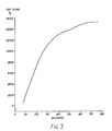
- the assembly is then heated, for example by RF power, within the bell jar 18 to a temperature of about 1500°C over a period of approximately 75 secs as per the heating schedule shown in Figure 3. This ensures the sealing composition 15 is heated to at least 1350°C which is necessary to form a glassy seal.
- the formed seal is then quenched by removing the heat and allowing the seal to cool naturally.
- the discharge arc tube 17 complete with cermet end closure assembly 10 sealed thereto by a glassy seal is inverted and the selected metal halide dose placed within the arc tube.
- This dose comprises 6.4 mg/cc of arc tube volume of sodium iodiode; 1.4 mg/cc of thallium bromide; 0.43 mg/cc of mercuric iodide; 0.21/mg/cc of indium and includes mercury in an amount between 5 to 30 mg per cc of arc tube volume, and, of course, the addition of the rare gas, Argon, between 1 to 300 Torr to aid starting.
- Suitable metal halides are the iodides, chlorides and bromides of tin, sodium, indium and thallium.
- cermet end closure assembly 10 plus sealing composition 15 is placed on top of the second end 19.
- the second end seal that is the final seal, is then completed by first using the procedure described above for obtaining the first end glassy seal.
- the second end or final glassy seal can be produced also in 75 secs.
- This sealing time for a glassy seal is extremely short. It does not include a cooling period and, therefore, can be compared directly with the sealing time of four minutes disclosed in EPO publication No 55049.
- the extremely short sealing time allows the dose to be sealed successfully within the arc tube without loss of fill due to volatilisation despite the proximity of the heating devices.
- some heat sinking can be used to facilitate the process.
- the glassy seals are converted to high softening temperature crystalline seals by subjecting them to a further heating schedule as shown in Figure 4.
- This is to be carried out in an atmosphere of rare gas, for example, argon. It is essential that the glassy seal or seals be heated to a minimum temperature of 1125°C and up to about 1200°C. In this example the measured temperature at the top of the cermet member 11, that is the cap temperature, was taken up to 1300°C so that the required temperature at the seal was achieved.
- the particular heating schedule used for conversion is shown in Figure 4. Because the conversion is so rapid, taking place in the last 10 seconds of the overall heating schedule of 60 seconds, the volatile dose does not escape even though the seal material is heated to a relatively soft glassy state while being converted.
- heating schedule which produces a crystalline seal in a single stage using a sealing composition sightly more refractory than the sealing compositions used with the heating schedules of figures 3 and 4.
- the cap temperature was 1620°C and the single sealing step was completed in 80 seconds.
- both ends of the arc tube are sealed using high softening-temperature crystalline seals.
- One end may be sealed by some other method, for example, direct sintering.
- Direct sintering of an electrically conductive cermet member to an insulating ceramic member in an end closure member for a discharge lamp is disclosed in our U.K. Patent 1571084.
- Direct sintering is also disclosed in the article "New structure of Ceramic Metal halide lamps there characteristics" by H. Kitagawa, S.Yamayaki and K. Takatsu of the Iwasaki Electric Company Limited, Japan presented at the I.E.S. Conference in Japan, May 27th 1985 which describes an investigation into an experimental metal halide lamp. The experimental lamp was life tested to 1,000 hours only and then analysed.
- FIG. 6 shows there is shown an arc tube having one end sealed by direct sintering.
- reference numeral 20 is a shaped polycrystalline alumina arc tube having a first end 21 closed by means of an electrically conductive cermet member 22 sintered directly to the alumina arc tube wall 23. Cermet member is complete with lead in 24 and electrode 25.
- the other end 26 is made in accordance with the present invention wherein electrically conductive cermet end member 27 is sealed within the ends of the arc tube envelope by means of an MgO, SiO2, A12O3 sealing composition converted from a glassy seal to a crystalline seal represented by reference number 28 and thickened line 29. Cermet member 27 is also complete with lead in 30 and electrode 31. Prior to the second end 26 being sealed the metal halide dose, plus some mercury and rare gas is inserted within the arc tube 20. A shaped ceramic arc tube has the advantage of providing a useful shielding of the dose behind the electrode, in contrast to the squared off ones of the embodiment of figure 2.
- a high pressure metal halide discharge lamp 32 in accordance with the present invention.
- This comprises a polycrystalline alumina discharge arc tube 33 which can be either of the monolith structure or a shaped envelope as described and complete with sealed in metal halide dose, mercury and rare gas.
- Arc tube 33 is supported on a nickel frame 34 within outer elliptical envelope 35 which is of soft glass, for example, soda glass.
- the outer envelope 35 is evacuated.
- the frame 34 includes leads 36, 37 sealed within glass flare 38. Getter rings 39, 40 are included to remove impurities and Edison screw attachment 41 completes the assembly.
- sealing compositions comprising MgO, SiO2, Al2O3 can be used in the practice of the present invention, for example, those sealing compositions disclosed in our EPO patent publication 55049.
- Preferred compositions comprise by weight from 51 to 62% SiO2, from 13 to 21% Al2O3 and from 25 to 28% MgO.
- the sealing compositions optionally may include up to 5% by weight of nucleating agents such as titania, zirconia or chromia to aid conversion, A particularly preferred composition by weight is 28.00% MgO, 20.00% Al2O3 and 52.00% SiO2.
- Another preferred composition because it is more refractory is by weight 13.1% MgO; 33.2% Al2O3; 36.5% and between 17.2% to 20% zirconium which is used in the heating schedule shown in Figure 5.
- high softening-temperature crystalline seal the term is meant to include any predominant degree of crystallinity which results in a seal which softens at the high temperature of between 1300°C and 1360°C and does not soften at any lower temperature. It would be preferable if 100% crystallinity was obtained for all such high temperature seals.
Landscapes
- Chemical & Material Sciences (AREA)
- Engineering & Computer Science (AREA)
- Ceramic Engineering (AREA)
- Materials Engineering (AREA)
- Structural Engineering (AREA)
- Organic Chemistry (AREA)
- Manufacturing & Machinery (AREA)
- Vessels And Coating Films For Discharge Lamps (AREA)
- Manufacture Of Electron Tubes, Discharge Lamp Vessels, Lead-In Wires, And The Like (AREA)
Description
- This invention relates to the manufacture of high pressure metal halide discharge lamps. More particularly the invention relates to a method of producing a metal halide discharge lamp having a ceramic arc tube and to a method of sealing electrically conducting cermet end closure members to arc tubes for such lamps. One of the problems facing the designer of a high pressure metal halide lamp intended for operation at low power 150 watts, and less is that of achieving adequate partial pressure of the metal halides, for example, the iodides, chlorides and bromides of tin, sodium indium and thallium. This generally requires the lamp to be arranged to operate at a relatively high minimum arc tube temperature (cool spot temperature) which becomes progressively more difficult to achieve as the designed input power of the lamp is reduced. Conventionally metal halide lamps utilise fused silica envelopes. On the other hand arc tubes made of light transmitting ceramic material, for example, polycrystalline alumina, sapphire or a spinel can withstand high temperatures, are less reactive than silica and can easily be made in small sizes. Ceramic arc tubes offer the potential of lamps operating at cool spot temperatures above 600°C and between 700°C and up to 1,000°C. The ability to operate at such high temperatures would enable the arc gap to be reduced, hence providing a more compact lamp. This would also mean the volt drop of the lamp could be reduced to between 80 to 130 volts. Thus the lamp could be run on commercially available control gear, for example, control gear which has been developed for use with high pressure sodium discharge lamp. For the first time, therefore, ceramic metal halide lamps could become commercially viable propositions.
- A main problem in making high pressure metal halide lamps with ceramic arc tube (hereinafter referred to as ceramic lamps) of small dimensions say of the
order 20 to 30mm in overall length with thearc gap 10 mm or less in length, is that of making the final seal without loss of volatile fill substances. Sealing such ceramic lamps involves heating parts of the ceramic arc tube to a high temperature, perhaps 1600°C and with such compact arc tubes the dose is only a short distance away. A further problem is that metal halide resistant sealing compositions comprising Mg0, Si0₂ and A1₂0₃, for example, those disclosed in our EPO publication 55049 produce glassy seals which soften at about 700oC and, therefore, would appear to be unsuitable for use in lamps designed to operate between 700°C and 1,000°C. - In its broadest aspect the present invention provides a method of manufacturing a high pressure metal halide discharge lamp having an arc tube of light transmitting ceramic material, said lamp being adapted to operate between 700°C and up to about 1,000°C and have a fill comprising a metal halide dose, mercury and a rare gas and wherein at least one electrically conductive cermet end closure member is sealed to an end of the arc tube by means of a rapidly formed high softening temperature crystalline seal, said method comprising the steps of first forming a glassy seal and then converting the glassy seal to a crystalline seal.
- In this specification where reference is made to a rapidly formed crystalline seal we mean that during formation of the seal it is not heated to a softened state for an excessive time which would allow the dose to escape. We do not exclude the possibility that the total sealing process may include longer periods during which the seal is not softened.
- Sealing of the dose within the arc tube envelope during lamp manufacture can comprise various stages, however, the most important stage is the final sealing step which takes place after the dose has been placed in the arc tube. If this is not successful, the volatile dose can be partially or completely lost so that lamp operation is affected or leaking dose material could even contaminate the seal material as the seal is being formed.
- According to a further aspect of the present invention there is provided a method of manufacturing a high pressure metal halide discharge lamp adapted to operate between 700°C and up to about 1000°C, the lamp including an arc tube of light transmitting ceramic material having a fill comprising a metal halide dose, mercury and rare gas; wherein the final sealing of the arc tube is accomplished by means of a final sealing step wherein sealing composition is formed into a glassy seal and then converted to a crystalline seal, the final sealing step being accomplished in less than four minutes so that loss of fill, is avoided.
- According to yet a further aspect of the invention there is provided a high pressure metal halide discharge lamp adapted to operate between 700°C and up to 1000°C the discharge lamp comprising an arc tube of light transmitting ceramic material, electrodes spaced in said arc tube by an arc gap of less than 10mm, the arc tube containing a metal halide dose, mercury and a rare gas for starting the lamp sealed within the ceramic arc tube by electrically conductive cermet end closure members in which the electrodes are located, at least one of the cermet end closure members being sealed to the end of the arc tube by means of a rapidly formed high softening temperature cyrstalline seal.
- As disclosed in our EPO publication No. 55049 glassy seals can be converted to a more refractory seal having a more crystalline structure. This can be accomplished by additional heat treatment for several hours at a temperature of up to 1,000°C. The components have to be held under pressure at about 700°C for 30 minutes followed by further heating still under pressure at 950°C for an hour or more. These processing times are roughly comparable with published patented processes for converting glasses to the crystalline state. In UK patent 1544779 processing times of between five and eight hours are mentioned while one or two hours is mentioned in UK patent 1048289. It is emphasised these two patents are not concerned with producing seals in metal halide lamps. During development work on producing high temperature operating ceramic metal halide lamps we have found that glassy seals can be converted to crystalline seals unexpectedly rapidly thereby allowing the complete production of crystalline seals in one and a half minutes or less. While it might be obvious that from a general production point of view that it would be desirable to reduce somewhat the processing times disclosed in our aforesaid EPO publication 55049 it is indeed surprising that it can be done in such a short space of time to produce rapidly formed crystalline seals. Even more surprising is the finding that arc tubes can stand the large amounts of heat required to melt the sealing material and applied to the arc tube in such a short period of time without cracking.
- EP-A-60582 describes a gas discharge lamp formed from two or more parts, at least one of which consists of an oxidic material, which is bonded by a metal oxide (cermet) to a metallic material.
- We have found that seals vary in their ability to convert from a glassy state to a fully crystalline state depending on their composition. In each case it is necessary to subject the glassy seals to a carefully controlled heating schedule. This should be arranged to subject the glassy seals to a temperature of at least 1125°C and up to about 1200°C. Maximum rate of conversion is found to take place at 1150+or-25°C and when fully crystalline some seals can withstand temperatures of between 1300°C and 1360°C without softening. Such seals are referred to herein as rapidly formed high softening temperature crystalline seals and this type of seal, therefore, is eminently suitable for use in metal halide discharge lamps wherein the temperature at the ends of the arc tube is of the
order 1000°C. - According to the invention there is provided a method of manufacturing a high pressure metal halide discharge lamp having an arc tube of light transmitting ceramic material, said lamp being adapted to operate between 700°C and up to about 1000°C and having a fill comprising a metal halide dose, mercury and a rare gas and wherein at least one electrically conductive cermet end closure member is sealed to an end of the arc tube by means of a crystalline seal, said method comprising the steps of first forming a glassy seal from a sealing composition comprising MgO, SiO₂, Al₂O₃ sealing material, and then converting the glassy seal to the crystalline seal characterised in that the crystalline seal is formed by subjecting the glassy seal to a temperature of at least 1125°C and up to about 1200°C, and wherein the respective steps of forming the glassy seal and of converting the glassy seal to the crystalline seal have a combined time of less than 4 minutes.
- One embodiment of the invention will now be described by way of example only and with reference to the accompanying drawings wherein:
- Figure 1 shows an end closure assembly used in the invention,
- Figure 2 shows diagrammatically the assembly of an end closure member to the end of a discharge arc tube used in practice of the invention,
- Figure 3 is a heating schedule used to obtain glassy seals in the practice of the invention,
- Figure 4 is a heating schedule to convert glassy seals to crystalline seals in accordance with the invention,
- Figure 5 is a heating schedule which produces a crystalline seal in a single step.
- Figure 6 is a shaped arc tube having one end only sealed in accordance with the invention, and
- Figure 7 is a high pressure metal halide discharge lamp in accordance with the invention.
- In Figure 1 there is shown an
end closure assembly 10 comprising an electrically conducting cermetend closure member 11 having electricallyconductive members 12 and 13 embedded therein. Member 12 forms a lead-in member andmember 13 forms a shank support forelectrode 14. Sealing glass or frit 15 comprising byweight 20% Al₂O₃; 28% MgO and 52% SiO₂ is pressed into a ring together with a PVA or other suitable binder. This binder is subsequently removed by baking in air. Ring 15 is deposited oncermet member 11 by premelting in a manner similar to that disclosed in our EPO publication 55049. Alternatively purification of the sealing composition to remove undesirable gases and substances can be done by heating under vacuum. As an alternative,frit ring 15 may be melted in situ with the arc tube. -
Cermet assembly 10 is placed loosely on top offirst end 16 of an empty polycrystallinealumina arc tube 17 as shown in figure 2, that is, as yet no dose is placed within thearc tube 17. The ends of the arc tube have first been formed by having a ceramic sealing element sintered within the arc tube in a well known manner to form a monolith structure. Bell jar 18 is placed over the loose assembly ofcermet member 11 and arctube 17. The bell jar is then evacuated or may be filled with a rare gas such as argon. Thecermet member 11 is maintained in position by application of load W as indicated by the arrows, which can be achieved by a simple weight or spring loaded device or equivalent such as bellows. The assembly is then heated, for example by RF power, within thebell jar 18 to a temperature of about 1500°C over a period of approximately 75 secs as per the heating schedule shown in Figure 3. This ensures thesealing composition 15 is heated to at least 1350°C which is necessary to form a glassy seal. The formed seal is then quenched by removing the heat and allowing the seal to cool naturally. - The
discharge arc tube 17 complete with cermetend closure assembly 10 sealed thereto by a glassy seal is inverted and the selected metal halide dose placed within the arc tube. This dose comprises 6.4 mg/cc of arc tube volume of sodium iodiode; 1.4 mg/cc of thallium bromide; 0.43 mg/cc of mercuric iodide; 0.21/mg/cc of indium and includes mercury in an amount between 5 to 30 mg per cc of arc tube volume, and, of course, the addition of the rare gas, Argon, between 1 to 300 Torr to aid starting. Suitable metal halides are the iodides, chlorides and bromides of tin, sodium, indium and thallium. Other metal halides may be used provided they are chemically compatible with the ceramic arc tube. For compact arc tubes envisaged by the present invention; that is, arc tubes having overall lengths not greater than 30 mm and down to 20 mm with arc gaps between 5 to 8 mm and not greater than 10 mm, and with arc tube diameter of 7.35 mm the dose would be only 11 to 12 mm from the heating devices used in the sealing procedure which, of course, considerably exacerbates the volatilisation problem. Once the fill has been placed in the arc tube, cermetend closure assembly 10 plussealing composition 15 is placed on top of thesecond end 19. The second end seal; that is the final seal, is then completed by first using the procedure described above for obtaining the first end glassy seal. By following this procedure the second end or final glassy seal can be produced also in 75 secs. This sealing time for a glassy seal is extremely short. It does not include a cooling period and, therefore, can be compared directly with the sealing time of four minutes disclosed in EPO publication No 55049. The extremely short sealing time allows the dose to be sealed successfully within the arc tube without loss of fill due to volatilisation despite the proximity of the heating devices. Although it is believed the success of the present invention is primarily due to the rapidity by which the final seal is made some heat sinking can be used to facilitate the process. - To complete the final seal the glassy seals are converted to high softening temperature crystalline seals by subjecting them to a further heating schedule as shown in Figure 4. This is to be carried out in an atmosphere of rare gas, for example, argon. It is essential that the glassy seal or seals be heated to a minimum temperature of 1125°C and up to about 1200°C. In this example the measured temperature at the top of the
cermet member 11, that is the cap temperature, was taken up to 1300°C so that the required temperature at the seal was achieved. The particular heating schedule used for conversion is shown in Figure 4. Because the conversion is so rapid, taking place in the last 10 seconds of the overall heating schedule of 60 seconds, the volatile dose does not escape even though the seal material is heated to a relatively soft glassy state while being converted. Since the actual conversion from a glassy state to a crystalline state has been observed to take place in the last 10 seconds of the 60 seconds heating schedule we believe other heating schedules could be devised to achieve run-up to conversion more quickly. It is believed, therefore that the process of conversion from a glassy state to a crystalline state could be accomplished in less than one minute. This excludes the cooling period because although a cooling step may be included the rate of cooling is relatively unimportant. It may be desirable to have a continuous process wherein the two heating stages would be applied in sequence. In figure 5 there is shown a heating schedule which produces a crystalline seal in a single stage using a sealing composition sightly more refractory than the sealing compositions used with the heating schedules of figures 3 and 4. In this case the cap temperature was 1620°C and the single sealing step was completed in 80 seconds. - It is not essential that both ends of the arc tube are sealed using high softening-temperature crystalline seals. One end may be sealed by some other method, for example, direct sintering. Direct sintering of an electrically conductive cermet member to an insulating ceramic member in an end closure member for a discharge lamp is disclosed in our U.K. Patent 1571084. Direct sintering is also disclosed in the article "New structure of Ceramic Metal halide lamps there characteristics" by H. Kitagawa, S.Yamayaki and K. Takatsu of the Iwasaki Electric Company Limited, Japan presented at the I.E.S. Conference in Japan, May 27th 1985 which describes an investigation into an experimental metal halide lamp. The experimental lamp was life tested to 1,000 hours only and then analysed. On a lamp operating at between 800°C to 900°C damage to the lower end of the lamp is reported in the article as being very severe. In figure 6 shows there is shown an arc tube having one end sealed by direct sintering. In figure 6,
reference numeral 20 is a shaped polycrystalline alumina arc tube having afirst end 21 closed by means of an electricallyconductive cermet member 22 sintered directly to the aluminaarc tube wall 23. Cermet member is complete with lead in 24 andelectrode 25. Theother end 26 is made in accordance with the present invention wherein electrically conductivecermet end member 27 is sealed within the ends of the arc tube envelope by means of an MgO, SiO₂, A1₂O₃ sealing composition converted from a glassy seal to a crystalline seal represented byreference number 28 and thickenedline 29.Cermet member 27 is also complete with lead in 30 andelectrode 31. Prior to thesecond end 26 being sealed the metal halide dose, plus some mercury and rare gas is inserted within thearc tube 20. A shaped ceramic arc tube has the advantage of providing a useful shielding of the dose behind the electrode, in contrast to the squared off ones of the embodiment of figure 2. - In Figure 7 there is shown a high pressure metal halide discharge lamp 32 in accordance with the present invention. This comprises a polycrystalline alumina
discharge arc tube 33 which can be either of the monolith structure or a shaped envelope as described and complete with sealed in metal halide dose, mercury and rare gas.Arc tube 33 is supported on anickel frame 34 within outerelliptical envelope 35 which is of soft glass, for example, soda glass. Theouter envelope 35 is evacuated. Theframe 34 includes leads 36, 37 sealed withinglass flare 38. Getter rings 39, 40 are included to remove impurities andEdison screw attachment 41 completes the assembly. - It is believed a wide range of sealing compositions comprising MgO, SiO₂, Al₂O₃ can be used in the practice of the present invention, for example, those sealing compositions disclosed in our EPO patent publication 55049. Preferred compositions comprise by weight from 51 to 62% SiO₂, from 13 to 21% Al₂O₃ and from 25 to 28% MgO. Also as disclosed therein the sealing compositions optionally may include up to 5% by weight of nucleating agents such as titania, zirconia or chromia to aid conversion, A particularly preferred composition by weight is 28.00% MgO, 20.00% Al₂O₃ and 52.00% SiO₂. Another preferred composition because it is more refractory is by weight 13.1% MgO; 33.2% Al₂O₃; 36.5% and between 17.2% to 20% zirconium which is used in the heating schedule shown in Figure 5. While we have used the term high softening-temperature crystalline seal the term is meant to include any predominant degree of crystallinity which results in a seal which softens at the high temperature of between 1300°C and 1360°C and does not soften at any lower temperature. It would be preferable if 100% crystallinity was obtained for all such high temperature seals.
- Although it is not inconceivable that other methods of sealing may not be found in the future it is the considered opinion of the inventors that successful sealing of metal halide lamps, especially the higher operating temperature compact lamps of the present invention, successful sealing will depend very largely, if not completely, on the extremely short sealing times disclosed herein.
- In the above description it will be appreciated that there will be variations in procedure depending on the actual ingredients of the sealing compositions used and lamp specification.
Claims (8)
- A method of manufacturing a high pressure metal halide discharge lamp having an arc tube of light transmitting ceramic material, said lamp being adapted to operate between 700°C and up to about 1000°C and having a fill comprising a metal halide dose, mercury and a rare gas and wherein at least one electrically conductive cermet end closure member is sealed to an end of the arc tube by means of a crystalline seal, said method comprising the steps of first forming a glassy seal from a sealing composition comprising MgO, SiO₂, Al₂O₃ sealing material and then converting the glassy seal to the crystalline seal characterised in that the crystalline seal is formed by subjecting the glassy seal to a temperature of at least 1125°C and up to about 1200°C, and wherein the respective steps of forming the glassy seal and of converting the glassy seal to the crystalline seal have a combined time of less than 4 minutes.
- A method according to claim 1, wherein the step of forming the glassy seal is completed within 75 seconds.
- A method according to claim 1, wherein the step of converting the glassy seal to a crystalline seal is completed within one minute.
- A method according to claim 1, 2 or 3, including the step of cooling the glassy seal prior to heating the glassy seal to convert it to a crystalline seal.
- A method according to claim 1, 2 or 3, wherein the crystalline seal is formed in a single continuous step.
- A method according to any one of claims 1 to 5, wherein the sealing of the arc tube is the final sealing step.
- A method according to any one of claims 1 to 6, wherein the sealing composition includes up to 20% of nucleating agent selected from titania, zirconia or chromia.
- A method according to any one of claims 1 to 7, wherein the length of the arc tube is not greater than 30mm.
Applications Claiming Priority (2)
| Application Number | Priority Date | Filing Date | Title |
|---|---|---|---|
| GB8521809 | 1985-09-03 | ||
| GB858521809A GB8521809D0 (en) | 1985-09-03 | 1985-09-03 | Metal halide discharge lamps |
Publications (3)
| Publication Number | Publication Date |
|---|---|
| EP0220813A2 EP0220813A2 (en) | 1987-05-06 |
| EP0220813A3 EP0220813A3 (en) | 1989-04-26 |
| EP0220813B1 true EP0220813B1 (en) | 1993-07-07 |
Family
ID=10584614
Family Applications (1)
| Application Number | Title | Priority Date | Filing Date |
|---|---|---|---|
| EP86306645A Expired - Lifetime EP0220813B1 (en) | 1985-09-03 | 1986-08-28 | Method for sealing the discharge tubes of metal halide high pressure discharge lamps |
Country Status (5)
| Country | Link |
|---|---|
| EP (1) | EP0220813B1 (en) |
| JP (1) | JPH0711947B2 (en) |
| DE (1) | DE3688672T2 (en) |
| GB (1) | GB8521809D0 (en) |
| HU (1) | HU194443B (en) |
Families Citing this family (8)
| Publication number | Priority date | Publication date | Assignee | Title |
|---|---|---|---|---|
| GB8707670D0 (en) * | 1987-03-31 | 1987-05-07 | Emi Plc Thorn | Ceramic metal halide lamps |
| GB8816510D0 (en) * | 1988-07-12 | 1988-08-17 | Emi Plc Thorn | Improvements in/relating to discharge lamp arc tubes |
| US6126889A (en) * | 1998-02-11 | 2000-10-03 | General Electric Company | Process of preparing monolithic seal for sapphire CMH lamp |
| JP3397145B2 (en) | 1998-09-18 | 2003-04-14 | ウシオ電機株式会社 | Ceramic lamp |
| US6430966B1 (en) * | 1999-07-30 | 2002-08-13 | Battelle Memorial Institute | Glass-ceramic material and method of making |
| ATE315014T1 (en) * | 1999-07-30 | 2006-02-15 | Battelle Memorial Institute | GLASS CERAMIC JOINING MATERIAL AND JOINING METHOD |
| US6949871B2 (en) * | 2002-06-24 | 2005-09-27 | Koninklijke Philips Electronics N.V. | Metal halide lamp with improved field wire |
| US20100071836A1 (en) * | 2008-09-19 | 2010-03-25 | Roy Watson | Sealing of Mica Wnidows for Geiger-Muller Tubes |
Citations (2)
| Publication number | Priority date | Publication date | Assignee | Title |
|---|---|---|---|---|
| EP0060582A1 (en) * | 1981-03-11 | 1982-09-22 | Koninklijke Philips Electronics N.V. | Composite body |
| GB2132011A (en) * | 1982-12-01 | 1984-06-27 | Philips Nv | Gas discharge lamp |
Family Cites Families (2)
| Publication number | Priority date | Publication date | Assignee | Title |
|---|---|---|---|---|
| GB1374605A (en) * | 1971-05-24 | 1974-11-20 | Pilkington Brothers Ltd | Method of manufacturing glass ceramic material |
| DE3174149D1 (en) * | 1980-12-20 | 1986-04-24 | Emi Plc Thorn | Discharge lamp arc tubes |
-
1985
- 1985-09-03 GB GB858521809A patent/GB8521809D0/en active Pending
-
1986
- 1986-08-28 DE DE19863688672 patent/DE3688672T2/en not_active Expired - Fee Related
- 1986-08-28 EP EP86306645A patent/EP0220813B1/en not_active Expired - Lifetime
- 1986-09-02 HU HU378486A patent/HU194443B/en not_active IP Right Cessation
- 1986-09-03 JP JP20609886A patent/JPH0711947B2/en not_active Expired - Lifetime
Patent Citations (2)
| Publication number | Priority date | Publication date | Assignee | Title |
|---|---|---|---|---|
| EP0060582A1 (en) * | 1981-03-11 | 1982-09-22 | Koninklijke Philips Electronics N.V. | Composite body |
| GB2132011A (en) * | 1982-12-01 | 1984-06-27 | Philips Nv | Gas discharge lamp |
Also Published As
| Publication number | Publication date |
|---|---|
| DE3688672D1 (en) | 1993-08-12 |
| EP0220813A3 (en) | 1989-04-26 |
| JPH0711947B2 (en) | 1995-02-08 |
| JPS6258563A (en) | 1987-03-14 |
| EP0220813A2 (en) | 1987-05-06 |
| HUT41557A (en) | 1987-04-28 |
| DE3688672T2 (en) | 1993-10-21 |
| GB8521809D0 (en) | 1985-10-09 |
| HU194443B (en) | 1988-01-28 |
Similar Documents
| Publication | Publication Date | Title |
|---|---|---|
| US3726582A (en) | Electric discharge lamp comprising container of densely sintered aluminum oxide | |
| US3363134A (en) | Arc discharge lamp having polycrystalline ceramic arc tube | |
| US5075587A (en) | High-pressure metal vapor discharge lamp, and method of its manufacture | |
| US6873108B2 (en) | Monolithic seal for a sapphire metal halide lamp | |
| EP0074720B1 (en) | Discharge lamps | |
| CN1217816A (en) | High-voltage metal-halide lamp | |
| US4011480A (en) | Electric discharge lamp | |
| US4160930A (en) | Electric discharge lamp with annular current conductor | |
| US3868528A (en) | Quartz pinches containing sealant glass | |
| JP2008124037A (en) | High pressure discharge lamp | |
| US3659138A (en) | Alumina-metal sealed lamp apparatus | |
| EP0220813A2 (en) | Method for sealing the discharge tubes of metal halide high pressure discharge lamps | |
| US6628082B2 (en) | Glow starter for a high pressure discharge lamp | |
| CA1060529A (en) | Current supply leadthroughs of high pressure lamps comprising borides of titanium or zirconium | |
| EP0187401A1 (en) | High-pressure discharge lamp | |
| EP0011993A1 (en) | Electric discharge lamps | |
| US2845557A (en) | Arc tube mounting | |
| EP0225944B1 (en) | Vapour discharge lamp | |
| JP4022302B2 (en) | Metal halide discharge lamp and lighting device | |
| EP0341749B1 (en) | Improved arc tube for high pressure metal vapor discharge lamp, lamp including same, and method | |
| US5208509A (en) | Arc tube for high pressure metal vapor discharge lamp | |
| CA2205327C (en) | Electrode assembly for high pressure sodium lamp and method of making same | |
| US5188554A (en) | Method for isolating arc lamp lead-in from frit seal | |
| US4295075A (en) | Arc discharge lamp having ceramic arc tube | |
| JPS6124125A (en) | Manufacturing of high pressure discharging lamp |
Legal Events
| Date | Code | Title | Description |
|---|---|---|---|
| PUAI | Public reference made under article 153(3) epc to a published international application that has entered the european phase |
Free format text: ORIGINAL CODE: 0009012 |
|
| AK | Designated contracting states |
Kind code of ref document: A2 Designated state(s): BE DE FR GB IT NL SE |
|
| RBV | Designated contracting states (corrected) |
Designated state(s): BE DE FR GB IT NL SE |
|
| PUAL | Search report despatched |
Free format text: ORIGINAL CODE: 0009013 |
|
| AK | Designated contracting states |
Kind code of ref document: A3 Designated state(s): BE DE FR GB IT NL SE |
|
| 17P | Request for examination filed |
Effective date: 19891011 |
|
| 17Q | First examination report despatched |
Effective date: 19910802 |
|
| RAP1 | Party data changed (applicant data changed or rights of an application transferred) |
Owner name: GE LIGHTING LIMITED |
|
| GRAA | (expected) grant |
Free format text: ORIGINAL CODE: 0009210 |
|
| AK | Designated contracting states |
Kind code of ref document: B1 Designated state(s): BE DE FR GB IT NL SE |
|
| PG25 | Lapsed in a contracting state [announced via postgrant information from national office to epo] |
Ref country code: IT Free format text: LAPSE BECAUSE OF FAILURE TO SUBMIT A TRANSLATION OF THE DESCRIPTION OR TO PAY THE FEE WITHIN THE PRE;WARNING: LAPSES OF ITALIAN PATENTS WITH EFFECTIVE DATE BEFORE 2007 MAY HAVE OCCURRED AT ANY TIME BEFORE 2007. THE CORRECT EFFECTIVE DATE MAY BE DIFFERENT FROM THE ONE RECORDED.SCRIBED TIME-LIMIT Effective date: 19930707 Ref country code: NL Effective date: 19930707 Ref country code: FR Effective date: 19930707 Ref country code: BE Effective date: 19930707 Ref country code: SE Effective date: 19930707 |
|
| REF | Corresponds to: |
Ref document number: 3688672 Country of ref document: DE Date of ref document: 19930812 |
|
| EN | Fr: translation not filed | ||
| NLV1 | Nl: lapsed or annulled due to failure to fulfill the requirements of art. 29p and 29m of the patents act | ||
| PG25 | Lapsed in a contracting state [announced via postgrant information from national office to epo] |
Ref country code: DE Effective date: 19940503 |
|
| PLBE | No opposition filed within time limit |
Free format text: ORIGINAL CODE: 0009261 |
|
| STAA | Information on the status of an ep patent application or granted ep patent |
Free format text: STATUS: NO OPPOSITION FILED WITHIN TIME LIMIT |
|
| 26N | No opposition filed | ||
| PGFP | Annual fee paid to national office [announced via postgrant information from national office to epo] |
Ref country code: GB Payment date: 20010803 Year of fee payment: 16 |
|
| REG | Reference to a national code |
Ref country code: GB Ref legal event code: IF02 |
|
| PG25 | Lapsed in a contracting state [announced via postgrant information from national office to epo] |
Ref country code: GB Free format text: LAPSE BECAUSE OF NON-PAYMENT OF DUE FEES Effective date: 20020828 |
|
| GBPC | Gb: european patent ceased through non-payment of renewal fee |
Effective date: 20020828 |