EP0220812A2 - Plattengerät mit hoher Kapazität - Google Patents
Plattengerät mit hoher Kapazität Download PDFInfo
- Publication number
- EP0220812A2 EP0220812A2 EP86306639A EP86306639A EP0220812A2 EP 0220812 A2 EP0220812 A2 EP 0220812A2 EP 86306639 A EP86306639 A EP 86306639A EP 86306639 A EP86306639 A EP 86306639A EP 0220812 A2 EP0220812 A2 EP 0220812A2
- Authority
- EP
- European Patent Office
- Prior art keywords
- micro
- hard disk
- disk drive
- drive system
- data
- Prior art date
- Legal status (The legal status is an assumption and is not a legal conclusion. Google has not performed a legal analysis and makes no representation as to the accuracy of the status listed.)
- Ceased
Links
Images


Classifications
-
- G—PHYSICS
- G11—INFORMATION STORAGE
- G11B—INFORMATION STORAGE BASED ON RELATIVE MOVEMENT BETWEEN RECORD CARRIER AND TRANSDUCER
- G11B33/00—Constructional parts, details or accessories not provided for in the other groups of this subclass
- G11B33/12—Disposition of constructional parts in the apparatus, e.g. of power supply, of modules
- G11B33/121—Disposition of constructional parts in the apparatus, e.g. of power supply, of modules the apparatus comprising a single recording/reproducing device
-
- G—PHYSICS
- G06—COMPUTING; CALCULATING OR COUNTING
- G06F—ELECTRIC DIGITAL DATA PROCESSING
- G06F3/00—Input arrangements for transferring data to be processed into a form capable of being handled by the computer; Output arrangements for transferring data from processing unit to output unit, e.g. interface arrangements
- G06F3/06—Digital input from, or digital output to, record carriers, e.g. RAID, emulated record carriers or networked record carriers
- G06F3/0601—Interfaces specially adapted for storage systems
- G06F3/0602—Interfaces specially adapted for storage systems specifically adapted to achieve a particular effect
- G06F3/0604—Improving or facilitating administration, e.g. storage management
- G06F3/0607—Improving or facilitating administration, e.g. storage management by facilitating the process of upgrading existing storage systems, e.g. for improving compatibility between host and storage device
-
- G—PHYSICS
- G06—COMPUTING; CALCULATING OR COUNTING
- G06F—ELECTRIC DIGITAL DATA PROCESSING
- G06F3/00—Input arrangements for transferring data to be processed into a form capable of being handled by the computer; Output arrangements for transferring data from processing unit to output unit, e.g. interface arrangements
- G06F3/06—Digital input from, or digital output to, record carriers, e.g. RAID, emulated record carriers or networked record carriers
- G06F3/0601—Interfaces specially adapted for storage systems
- G06F3/0602—Interfaces specially adapted for storage systems specifically adapted to achieve a particular effect
- G06F3/0625—Power saving in storage systems
-
- G—PHYSICS
- G06—COMPUTING; CALCULATING OR COUNTING
- G06F—ELECTRIC DIGITAL DATA PROCESSING
- G06F3/00—Input arrangements for transferring data to be processed into a form capable of being handled by the computer; Output arrangements for transferring data from processing unit to output unit, e.g. interface arrangements
- G06F3/06—Digital input from, or digital output to, record carriers, e.g. RAID, emulated record carriers or networked record carriers
- G06F3/0601—Interfaces specially adapted for storage systems
- G06F3/0628—Interfaces specially adapted for storage systems making use of a particular technique
- G06F3/0655—Vertical data movement, i.e. input-output transfer; data movement between one or more hosts and one or more storage devices
- G06F3/0658—Controller construction arrangements
-
- G—PHYSICS
- G06—COMPUTING; CALCULATING OR COUNTING
- G06F—ELECTRIC DIGITAL DATA PROCESSING
- G06F3/00—Input arrangements for transferring data to be processed into a form capable of being handled by the computer; Output arrangements for transferring data from processing unit to output unit, e.g. interface arrangements
- G06F3/06—Digital input from, or digital output to, record carriers, e.g. RAID, emulated record carriers or networked record carriers
- G06F3/0601—Interfaces specially adapted for storage systems
- G06F3/0668—Interfaces specially adapted for storage systems adopting a particular infrastructure
- G06F3/0671—In-line storage system
- G06F3/0673—Single storage device
- G06F3/0674—Disk device
-
- G—PHYSICS
- G11—INFORMATION STORAGE
- G11B—INFORMATION STORAGE BASED ON RELATIVE MOVEMENT BETWEEN RECORD CARRIER AND TRANSDUCER
- G11B20/00—Signal processing not specific to the method of recording or reproducing; Circuits therefor
- G11B20/10—Digital recording or reproducing
-
- G—PHYSICS
- G11—INFORMATION STORAGE
- G11B—INFORMATION STORAGE BASED ON RELATIVE MOVEMENT BETWEEN RECORD CARRIER AND TRANSDUCER
- G11B25/00—Apparatus characterised by the shape of record carrier employed but not specific to the method of recording or reproducing, e.g. dictating apparatus; Combinations of such apparatus
- G11B25/04—Apparatus characterised by the shape of record carrier employed but not specific to the method of recording or reproducing, e.g. dictating apparatus; Combinations of such apparatus using flat record carriers, e.g. disc, card
- G11B25/043—Apparatus characterised by the shape of record carrier employed but not specific to the method of recording or reproducing, e.g. dictating apparatus; Combinations of such apparatus using flat record carriers, e.g. disc, card using rotating discs
-
- G—PHYSICS
- G11—INFORMATION STORAGE
- G11B—INFORMATION STORAGE BASED ON RELATIVE MOVEMENT BETWEEN RECORD CARRIER AND TRANSDUCER
- G11B5/00—Recording by magnetisation or demagnetisation of a record carrier; Reproducing by magnetic means; Record carriers therefor
- G11B5/012—Recording on, or reproducing or erasing from, magnetic disks
-
- G—PHYSICS
- G06—COMPUTING; CALCULATING OR COUNTING
- G06F—ELECTRIC DIGITAL DATA PROCESSING
- G06F3/00—Input arrangements for transferring data to be processed into a form capable of being handled by the computer; Output arrangements for transferring data from processing unit to output unit, e.g. interface arrangements
- G06F3/06—Digital input from, or digital output to, record carriers, e.g. RAID, emulated record carriers or networked record carriers
- G06F3/0601—Interfaces specially adapted for storage systems
- G06F3/0668—Interfaces specially adapted for storage systems adopting a particular infrastructure
- G06F3/0671—In-line storage system
- G06F3/0673—Single storage device
-
- Y—GENERAL TAGGING OF NEW TECHNOLOGICAL DEVELOPMENTS; GENERAL TAGGING OF CROSS-SECTIONAL TECHNOLOGIES SPANNING OVER SEVERAL SECTIONS OF THE IPC; TECHNICAL SUBJECTS COVERED BY FORMER USPC CROSS-REFERENCE ART COLLECTIONS [XRACs] AND DIGESTS
- Y02—TECHNOLOGIES OR APPLICATIONS FOR MITIGATION OR ADAPTATION AGAINST CLIMATE CHANGE
- Y02D—CLIMATE CHANGE MITIGATION TECHNOLOGIES IN INFORMATION AND COMMUNICATION TECHNOLOGIES [ICT], I.E. INFORMATION AND COMMUNICATION TECHNOLOGIES AIMING AT THE REDUCTION OF THEIR OWN ENERGY USE
- Y02D10/00—Energy efficient computing, e.g. low power processors, power management or thermal management
Definitions
- the present invention relates to a micro-hard disk drive system, and in particular, a micro-Winchester high capacity disk drive with integral controller electronics.
- Winchester disk drives As replacements and enhancements to floppy disk drives for program storage.
- the Winchester disk drive in general provides higher capacities and faster speeds of operation, factors which are important for the effective use of personal computers running advanced software packages.
- Winchester disk drives that have been developed in that regard were based upon the use of hard disks of diameter of approximately five and one-quarter inches, also known as mini-Winchester disks. Such so called “five and one-quarter inch” disk drives have generally developed as an "industry standard.” Such Winchester disk drive systems can typically store 5-30 Megabytes of information when designed arnund an open-loop positioning system using a stepper motor capable of supporting up to approximately 360 data tracks per inch.
- steps made by the assignee of the present invention have expanded the storage capacity of the typical five and one-quarter inch disk drive up to,600 tracks per inch using the same basic type of open-loop positioning system. Such a track density had previously been believed unobtainable with stepper motor technology.
- US-A-4,392,095 entitled “Method of and Apparatus for Generating a Unique Index Mark from the Commutation Signal of a DC Brushless Motor,” discloses a system for providing a unique index mark relative to the computer disk which is required for avoiding errors in addressing a memory location on the disk surface. That index mark is provided by correlating the commutation signal from a dc motor with a synchronizing signal present on one or more discrete tracks of the computer disk.
- EP-A- entitled "Read/Write Head Thermal Compensation System” discloses a thermal compensation system used by Rodime PLC in its five and one-quarter inch disk drive systems. The positioning mechanism of that system is shown in Figure 5 of the present application. That thermal compensation system uses different materials with different co-efficients of thermal expansion for various components of the positioning mechanism for the read/write head used in the disk drive system. In the operation of that thermal compensation system, in response to a change in temperature, a mispositioning of the read/write head is compensated for by a counter-movement due to the selection of various materials with different co-efficients of thermal expansion within the mechanical arrangement.
- US-A- entitled “Method and Apparatus for Controlling a Stepper Motor,” discloses a system for minimizing oscillations of the stepper motor for a single step, minimizing the time taken for the stepper motor to move between tracks for multi-track seek operations and reducing the angular hysteresis due to the mechanical and magnetic properties of the stepper motor construction.
- a microprocessor circuit is adapted to drive the stepper motor in accordance with predetermined programs.
- US Patent Application Serial No 582,554 entitled “Micro-Hard Disk Drive System,” discloses a high-density micro-Winchester hard disk system using a hard disk of approximately three and one-half inches and having digital information stored at a density of approximately 600 concentric tracks per inch, and at a storage density equivalent to at least 5 Megabytes per hard-disk.
- a stepper motor is designed to increment in steps of 0.9° which causes the read/write head to move from one track to the next adjacent track on the hard disk.
- Such increased storage capacity allows the use of more sophisticated programs and the storage of data for use therewith than has been possible heretofore.
- Such prior art disk drives almost exclusively used the "industry standard" ST 506 interface to the host system. That interface has the disadvantage that it defines fundamental operating parameters of the disk drive, such as MFM (modified frequency modulation) coding, data transfer rate and disk rotational speed, which limit the storage capability of the disk drive.
- MFM modified frequency modulation
- the ST 506 interface further requires additional controller electronics to be provided by the user to carry out formatting, MFM encode/decode, block address decode, error detection/ correction and other functions.
- micro-Winchester disk refers to a Winchester disk of 85-100 millimeters in diameter, with the preferred embodiment being approximately 96 millimeters.
- a Winchester disk of that size can also be referred to as a "3.5 inch” Winchester disk.
- That high capacity micro-Winchester disk drive system was developed to incorporate the 600 tracks per inch open-loop positioning capability previously developed by the assignee, and utilizes a slower disk rotational speed and 2,7 RLL (Run Length Limited) coding for achieving a storage capacity heretofore unachievable in a micro-Winchester hard disk.
- Such new disk drive system by virtue of its small size, vibrational isolation, integral controller and high storage capacity, is ideally suited for use in both personal and portable computer system.
- the high capacity disk drive system is constructed for operating micro-Winchester computer disks.
- This disk drive system provides fast access to a high capacity data storage for use with small business computers, terminals, and microprocessor-based systems, portable or otherwise, and many other areas where compact, rugged and lightweight hard disk storage is required.
- the disk drive system normally utilizes either one or two hard disks such as Winchester disks, and provides data storage on each disk in excess of 10 Megabytes once the disks are formatted.
- the system is capable of storing in excess of 12.5 Megabytes per disk with the disk unformatted. It should be understood, however, that data is recorded on both sides of each disk.
- Each of the hard disks is mounted for rotation within the housing of the hard disk drive system.
- each of those hard disks is 96 millimeters in diameter.
- a transducer which includes twn read/write heads for each disk within the system, one head positioned on each side of the disk, writes digital information on and reads digital information from the hard disk.
- the disk drive system operates such that information is stored on the disk at a density of at least 600 concentric tracks per inch.
- a positioning mechanism moves the transducer between the tracks on the computer disk for writing information and reading information from the disk.
- the heretofore unachievable storage capacity is achieved by the present invention by operating the disk at a rotational speed of approximately 2746 RPM, and by coding the data before it is recorded on the disk using a 2,7 RLL coding technique.
- the positioning mechanism of the disk drive system is arranged for moving the transducer along a path extending in an approximately radial direction with respect to the hard disk so that the transducer can move between the inner-most and outer-most tracks on the disk.
- the positioning means moves the transduer along an arcuate path that extends in the radial direction with respect to the disk.
- the positioning mechanism of the disk drive system includes a stepper motor and a mechanism for operating the stepper motor in full step increments. In the operation of the stepper motor, each step increment is approximately 0.9°. Each step movement of the stepper motor causes the transducer to move from one track to the next adjacent track.
- Each read/write head of the transducer is arranged on one end of a support arm, or flexure, which extends in a radial direction with respect to the computer disk.
- a positioning arm is attached to the other end of the support arm. The positioning arm has one end coupled to a pivot shaft for enabling the positioning arm to be pivoted about the axis of the pivot shaft. That pivot shaft is located on one side of the support arm and is spaced away from that arm.
- the stepper motor has an output drive shaft for controlling the movement of the positioning arm.
- a tensioned steel band is coupled to the drive shaft of the stepper motor via a pulley and is also coupled to both the end of the positioning arm on the opposite side of the support arm from the pivot shaft, and to a tensioning spring attached to the positioning arm.
- the steel band is connected in a pulley arrangement for coupling the drive shaft of the stepper motor to the positioning arm such that rotational movement of the stepper motor causes the positioning arm to pivot about the pivot shaft. The pivoting movement of the positioning arm in turn moves the support arm and the transducer in incremental steps across the tracks of the disks.
- the positioning arm is coupled directly to the pivot shaft, which itself is free to rotate by means of a bearing assembly which includes a pair of ball bearings arranged in a back-to-back configuration with a dimensional pre-load of approximately 5 pounds force.
- the stepper motor that is used for driving the positioning arm is a two- phase bi-polar stepper motor that operates in a full step mode.
- the tensioned steel band that interconnects the stepper motor to the positioning arm is a band etched from stainless steel with a tensile strength of greater than approximately 250,000 Psi.
- the materials for each of the components are selected to automatically compensate for any mispositioning between the transducer and a track caused by thermal effects.
- the positioning mechanism includes a primary thermal loop that, on average, causes the transducer to move inwardly from a track center as temperature rises.
- a second thermal loop is provided that causes a counter-movement to the movement caused by the primary thermal loop,thereby tending to maintain the transducer on the track centerline.
- the positioning arm is formed of a first material.
- the disk and housing are formed of a second material.
- the pivot shaft, head support arm and metal band are formed of a thid material.
- Those first, second and third materials have different co-efficients of thermal expansion.
- the arrangement, geometry and selection of materials of those parts are such that, in response to a change in temperature, the various components of the positioning system react in such a way that the support arm effectively rotates via the positioning arm and the pivot shaft so as to maintain the transducer substantially at its original track position. Consequently, the positioning system self-compensates for any movement that would be caused by changes in temperature.
- the high capacity disk drive system includes a housing in which the micro-hard disk, the transducer, the transducer pre-amplifier, and at least a portion of the positioning mechanism are contained. That housing is arranged within a first frame which holds the housing. A set of anti-vibration mounts secures the housing within the frame so as to minimize the transmission of shock or vibration from the frame to the housing. In addition, the frame supporting the housing holding the disk drive system can be arranged within a second larger frame.
- the frame for the high capacity micro-Winchester disk drive system can be held within a larger frame that would fit within an opening normally designed for use by either a regular five and one-quarter inch disk drive system or so-called "half-height" five and one-quarter inch disk drive system.
- the electronics of the high capacity micro-Winchester disk drive system have been developed utilizing LSI circuits with the entire control circuit, except the pre-amplifier, being arranged on a single- printed circuit board.
- Providing electronic functions of the drive on a single printed circuit board whose dimensions do not exceed the overall dimensions of the drive permits full utilization of the anti-vibration mounting systems and thus makes it possible to utilize the high capacity micro-Winchester disk drive of the present invention in portable computer systems.
- the electronic functions have been implemented, in part, in several integrated circuit chips of different types with the objective of functioning with a minimum use of power.
- An additional feature in this regard is the location of the pre-amplifier for the read/write heads, which is mounted within the clean chamber as close as possible to the head assembly in order to minimize noise pick-up. That obviously provides for the increased probability of error-free operation during the reading and writing of information from and to the disk.
- An additional feature is the use of a microprocessor routine which substantially reduces the power used by the stepper motor when the disk drive is de-selected by the host computer system. That "power-save" capability and low average power consumption are desirable properties of a hard disk drive when used in a portable computer system, since they result in less heat dissipation, thereby minimizing the requirement of the computer system to provide noisy, heavy and bulky air-extraction fans.
- Still another preferred feature of the present invention is the use of an ANSI X3T9.2 SCSI (Small Computer System Interface) in conjunction with the on-board microprocessor of the drive to interface with the host computer.
- SCSI Small Computer System Interface
- 2,7 RLL encode and decode to NRZ, and a disk rotational speed of 2746 RPM the disk drive will operate with its integral controller performing all functions normally associated with a separate host controller device.
- the disk drive thus need include only an SCSI interface, controller logic and drive logic.
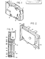
- FIG. 1 a high capacity micro-Winchester disk drive system in accordance with the present invention.
- the high capacity disk drive includes a housing 2 which is mounted within a frame 4.
- the frame 4 is attached to a face plate, or facia 6.
- the face plate 6, together with housing 2 and frame 4 may be slid into a slot provided within a computer for the disk drive system.
- a plurality of anti-vibration mounts 8, 10, 12, and 14 are provided.
- the housing 2 with the frame 4 is placed inside of a second frame. That second frame is formed by top frame member 16, bottom frame member 18 and a cross bar 20. The second frame is attached to a face plate 22 and to the first frame 4.
- the high capacity disk drive system in accordance with the preferred embodiment of the present invention is a micro-processor based device which receives and transmits 2-to-7 RLL (Run Length Limited) data, seeking the appropriate track in response to step commands across the disk control interface.
- the drive is fully soft sectored and is connected to the host computer via an on-board intergral disk controller which communicates with the host computer via a Small Computer Systems Interface (SCSI). Interleave factors of 1 and a "host interface" data rate of up to 1.5 megabytes per second are utilized by the present invention to attain maximum performance.
- the integral disk drive controller is responsible for formatting, 2-to-7 RLL encode and decode to NRZ, block address decode, CRC generation and verification and other functions.
- the microprocessor is responsible for the control of the stepper motor used for positioning. Fast seek times are achieved by the use of programmed velocity profiles and micro-stepped damping routines. Automatic thermal compensation has been built into the head positioning mechanism.
- FIG. 3 A sectional view of the high capacity disk drive of the present invention is shown in Figure 3.
- two micro-Winchester disks, 24 and 26 are arranged on the hub 54 of a dc motor 32 for rotation within the housing.
- Magnetic heads 28 and 30 are attached to support arms 31, which in turn are coupled to a stepper motor 42 through a drive band assembly 40 and a positioning arm 41.
- a flat cable flexible circuit 55 which includes the read/write, head select and pre-amplification circuitry for the drive.
- Such flat cable flexible circuitry serves as the electrical interface between the heads 28 and 30 and the circuit board 46 and may preferably be an SSI 117 IC.
- High storage capacity is achieved because the disk drive system of the present invention records data on the disks at a rate of 7.5 Megabits per second using 2,7 RLL encoding with the disk rotating at 2,750 revolutions per minute.
- the recording rate, encoding scheme and rotational speed are a departure from the constraints of the industry standard ST 506 interface, and are possible by having an integral controller and SCSI host interface.
- Those parameters when applied to a micro-Winchester disk drive system in accordance with the preferred embodiment of the present invention, provide a storage capacity of at least 10 Megabytes per disk.
- a breather filter 34 is provided on the top cover 38 of the disk housing 50, adjacent to the center of the spindle of the dc motor 32.
- a recitculating filter 36 is located inside the chamber 52 at one corner in a suitable position in order to filter the flow of air resulting from the pumping effect of the rotating disks 24 and 26 when the disk drive is in operation.
- the top cover 38 seals the open face of the enclosure by means of a continuous gasket.
- the electronics board 46 is fixed to the base of the chamber 52, covering the full area (except for the stepper motor 42) of that face of the disk drive.
- the dc motor is fixed to the base of the chamber and is largely obscured from view by the electronics board 46.
- the positioning mechanism is shown in greater detail in Figure 4. That positioning mechanism is mounted on the base of housing 50 within chamber 52 of the disk drive system. Chamber 52 is formed by chamber housing 50 and top cover 38. Winchester disk 24 is mounted on a hub assembly 54 within the chamber housing 52 so that it is rotated within the chamber by the dc motor 32.
- the typical read/write magnetic head 28 is mounted on one end 56a of a flexure 56 which serves as the support arm.
- the other end 56b of flexure 56 is attached to a positioning arm 60.
- Flexure 56 is a thin rectangular stainless steel coil.
- Positioning arm 60 is coupled to a steel pivot shaft 62. That steel shaft 62 is fixed to the inner races of a pair of pre-loaded steel ball bearings (not shown), which in turn are located in the base of housing 50. Pivot shaft 62 rotates about a pivot axis 64.
- the side of the positioning arm 60 opposite from the shaft 62 has a curved portion 66.
- a steel spring arm 74 is attached to the positioning arm 60.
- a tensioned steel band 68 is wrapped around and attached to the steel pulley 76 mounted on the drive shaft 78 of the stepper motor.
- the stepper motor is fixed to the base of the housing 50.
- the two ends of the steel band, 70 and 72, are attached to arms 74 and 66 respectively.
- the first class of material is an aluminium/bronze alloy
- the second class of material is stainless steel
- the third class of material is aluminium.
- disk 24 (wrought aluminum); housing 50 (die cast aluminium alloy 1M 2); positioning arm 60 (aluminium/bronze alloy); metal band 68 (Sandvik 11 R 51 steel); and flexure support 56 (AISI 301 stainless steel).
- the dimensions and arrangement of these various components are such that, in response to changes in temperature, the various materials expand or contract in such a way that the support arm (flexure) effectively rotates via the positioning arm and the pivot shaft so as to maintain the typical read/write head substantially at its original track position.
- thermal circuits effectively controlling the positioning of the read/write head 28 to a track on the disk 24 consisting of a primary thermal circuit and a compensating thermal circuit.
- the primary thermal circuit operates in chamber 52 and links the track on the disk 24 to the hub 54, to the motor 32, to the base of housing 50, to the bearings for shaft 62, to the shaft 62, to the arm 60, to the flexure 56, and to the read/write head 28.
- the compensating circuit also operates in chamber 52 and links the arm 60 to the bad 68, to the pulley 76, to the stepper motor shaft 78, to the stepper motor, to the base of housing 50, to the bearings for shaft 62, to shaft 62 and to the arm 60.
- the primary thermal circuit and the compensating thermal circuit have arm 60, pivot shaft 62, housing 50 and the circulating air in chamber 52 in common.
- the primary thermal circuit in chamber 52 results in a misposition of head 28 relative to a track on the disk 24.
- the compensating circuit of chamber 52 causes the shaft 62 to rotate in such a way as to substantially move the read/write head 28 to its original position relative to the disk. That operation is described more fully below.
- a temperature change in chamber 52 causes the read/write head 28 to move relative to a track on the disk 24 because of varying contributions from flexure 56, housing 50 and the positioning arm 60 in the primary thermal circuit.
- the resulting misposition varies according to track position (proportional to the angle of shaft 62 and the arm 60 relative to the "line” drawn between the center of the hub 54 and the shaft axis 64).
- track position proportional to the angle of shaft 62 and the arm 60 relative to the "line” drawn between the center of the hub 54 and the shaft axis 64.
- the compensating thermal circuit in chamber 52 acts to reduce that misposition to acceptable proportions for all track positions. With temperature changes, the various components of the compensating circuit vary in length relative to each other. A change in geometry causes rotation of the arm 60 about the axis of the shaft 62, thus compensating for the read/write head 28 and the disk 24 misposition over the prescribed track position and temperature range of the disk drive.
- the dc motor 32 is a brushless 2-phase external rotor dc motor with integral hub. Commutation is effected by a Hall sensor. A spare Hall sensor is provided in the motor and may be activated in the event that the first Hall element fails.
- the motor uses preloaded ABEC 7 bearings and is balanced in two planes to better than 0.25 grams centimeters. A ferrofluidic seal is fitted above the top bearing.
- the disk hub 54 is grounded to the electronics board 46 by the motor shaft and a button contact in order to prevent build-up of static charge on the rotating disks.
- the high capacity disk drive of the present invention is not fitted with a separate transducer for generating an index pulse. Instead, the Hall generator in the dc motor is used although it provides two identical pulses per disk revolution. A unique pulse is selected during the power-up sequence by a routine in the microprocessor which detects a pre-recorded data burst. The index/Hall phase which is active when the data burst is detected is thus automatically selected.
- the disks 24 and 26 are rotated at a speed of 2746 plus or minus 27 rpm.
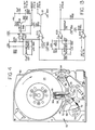
- the electronics developed for the high capacity micro-Winchester disk drive system of the present invention were designed primarily as large scale integrated circuits (LSI) that are placed on a single printed circuit board (with the exception of the pre-amplification, read/write and head circuitry), as shown in Figure 6.
- LSI large scale integrated circuits
- the use of only a single printed circuit board whose dimensions lie within the outline dimensions of the housing 50 is particularly beneficial in enabling the dual anti-vibrational mounting arrangement of the present invention to be utilized for mounting the high capacity micro-Winchester disk drive system in the space normally provided for a 5-1/4 inch disk drive system. Consequently, an extremely rugged, low weight, high capacity hard disk drive system is provided for use in a portable computer.
- the development of such a single printed circuit board electronic control circuit in the high capacity micro-Winchester disk drive system has enabled the power consumption and dissipation to be significantly reduced.
- the electronic circuits in the preferred embodiment provide heat dissipation at a rate of between 9 and 13 watts as compared to 25 watts typically dissipated by a 5-1/4 inch Winchester disk drive system.
- the high capacity micro-Winchester disk drive system of the present invention dissipates a relatively small amount of heat into the computer system. That enables a portable computer to utilize either a smaller fan or to entirely eliminate the use of a fan for removing heat from the system.
- a microprocessor 100 is used to control all drive and interface functions.
- the microprocessor 100 is connected via a microprocessor data bus to both Dual Part Buffer Controller 102 and the disk controller 104.
- the micro-processor 100 is connected to control both the stepper motor drive 42 and control circuitry 106 and the spindle motor drive 32, both of which drives are connected in the usual manner to the head/disk module 110.
- the microprocessor 100 is also connected to control the SCSI Inferface 103.
- Data read from the magnetic disks 24 and 26 is preamplified by head preamplifier 112 and fed through disk pulse detector 114 and data separator 116 to encoder/decoder 118.
- the disk pulse detector 114 amplifies, filters and then differentiates the data signals received from the heads 28 and 30. Its output is a TTL compatible signal which, on the positive leading edge, indicates a signal peak. Electrically, those peaks correspond to the l's or flux reversals recorded on the disk 24 and 26.
- the output of the disk pulse detector 114 is fed to the data separator logic 116. After locking onto the frequency of the input pulses, the data separator 116 separates them into synchronized data and clock signals. The data separator is able to lock onto the receiving preamble data pattern extremely quickly, such that lock indication occurs within four bytes.
- the encoder/decoder 118 which receives the output from the data separator 116, is an LSI device which provides an efficient interface between the NRZ data required by the disk controller 104 and the 2,7 RLL recording code used in the disk drive.
- This chip may preferably be an AIC-270, manufactured by Adaptec. Such chip performs all of the functions necessary to convert the NRZ data to and from the 2,7 RLL data. It also incorporates address mark generation and detection logic.
- the encoder/decoder is connected via a high speed bus to the disk controller 104.
- the disk controller 104 is connected via a high-speed buffered data bus to both the data buffer RAM 120, the Dual Port Buffer Controller 102 and the SCSI Interface 103.
- the encoder/decoder 118 is also connected, through the SCSI interface 103 to the data port of the SCSI bus 124.
- the microprocessor 100, the disk controller 104 and the SCSI bus controller 102 perform the controller logic function for the disk drive system. Both the disk controller 104 and the SCSI bus controller 102 are initialized and monitored by microprocessor 100.
- the microprocessor is used to maintain "loose" synchronization with the real time operation of the disk through registers in the disk controller 104. Based upon the real- time events occurring on the disk, the microprocessor also sets up the registers in the SCSI bus controller 102, in order to control data transfers to and from the RAM 120.
- the microprocessor 100 also performs the following functions: recalibrates the disk drive to Track 0; monitors for fault conditions; selects the appropriate head; seeks to the desired cylinder; reads the command data block sent by the host computer and then performs the operations necessary for the command to be executed; and sends status reports back to the host computer via the SCSI bus 124.
- a flow chart showing the design of a program for operating the microprocessor 100 is set forth in Figure 15. That program is stored in a EPROM contained within the electronic circuitry of the disk drive system.
- the disk controller 104 performs the basic read/write functions. It may preferably be an AIC-010L Winchester Disk Controller chip, manufactured by Adaptec. That chip provides the necessary serialization, de-serialization, formatting ECC generation and correction functions. In addition, the disk controller 104 has search and verify capabilities.
- the disk controller 104 is connected through the encoder/decoder 118 to a write precompensation circuit 117. That circuit, which may be a semi-custom chip (ULA), model number 5RA0 ⁇ 97Q1, manufactured by Ferranti Electronics Limited, provides precompensation to the 2,7 RLL encoded data stream prior to its application to the preamplifier 112 and then to the heads 28 and 30.
- UMA semi-custom chip
- the SCSI bus controller 102 is designed to simplify the buffering and increase the throughput of data blocks. It may preferably be an AIC-300L dual port buffer controller IC manufactured by Adaptec. It allows low cost static RAM to be used as a dual port circuit or FIFO, supervises data transfers to the data buffer 120, reduces the possibility of host overruns and allows for very high speed direct
- DMA dynamic random access
- the microprocessor 100 supervises the operation of the disk controller 104 and the SCSI bus controller 102, allocating buffer space, starting and stopping the two controllers, and implementing operation of the ECC correction logic. SCSI interface command decoding, logical address conversion to cylinder, disk format and multi-block read/write control are also implemented by the microprocessor. In addition, all of the normal functions required by an ST 506 drive are performed. Seek implementation, spindle motor speed, checking and verification and general house-keeping are likewise performed by the microprocessor 100.
- IC-1 which is an 8031 microprocessor used to control all drive logic and controller logic functions, as described above. It is connected to IC-2, which may be an SN74LS373FN octal D-type transparent latch, which is used to pick-up and latch the least significant byte of the address from the multiplexed data bus received from the microprocessor.
- the latch IC-2 is connected to a 2764 EPROM IC-3, as is the microprocessor IC-1. That memory is used to store the software program for the microprocessor.
- Both the microprocessor IC-1 and the EPROM IC-3 are connected to a second octal D-type latch IC-4, which may be the same integrated cirucit as IC-2. That latch is used to pick up and latch data from the multiplexed bus.
- IC-5 may be an SN74ALS638-1FN octal bus transceiver chip and is used to buffer data signals to and from the SCSI bus.
- IC-6 is a similar octal bus transceiver and is used to buffer control signals onto the SCSI bus.
- IC-7 is an SN74LS240 octal buffer integrated circuit which buffers the control signals from the SCSI bus.
- IC's 5, 6 and 7 are connected to IC-8 which is a semi-custom chip, part number LSA0132 manufactured by LSI Logic Corporation.
- IC-8 is used to control the interface between the drive and the SCSI bus. It also handles the generation of system clocks and other peripheral functions.
- IC-9 which is connected to receive an output from IC-8, is a 2K x 8 static RAM chip which is used to store data from the disk or SCSI bus and may preferably be an HM6116FP integrated circuit device.
- Static RAM chip IC-9 is also connected to a dual port buffer controller IC-10, which may be an AIC-300L device made by Adaptec.
- IC-10 allows the static RAM chip IC-9 to be utilized as a dual port circular FIFO, supervises data transfers to that RAM, and allows for high speed DMA transfers.
- the dual port buffer controller IC-10 is connected to IC-11, which may be an AIC-010L Winchester disk controller, and is also manufactured by Adaptec.
- IC-11 performs the basic read/write functions for the drive of the present invention. For that purpose, IC-11 provides the necessary serialization/de-serialization, formatting, ECC generation and correction functions.
- the Winchester disk controller chip also has search and verify capabilities.
- IC-12 is a 2,7 RLL encoder/decoder device. It may preferably be an AIC-270 IC, manufactured by Adaptec. IC-12 performs all of the functions necessary to convert the incoming NRZ coded data to and from the 2,7 RLL data as written to and read from the disks.
- the disk pulse detector IC-13 may preferably be a DP8464B integrated circuit. It produces a TTL compatible output which, on the positive leading edge, indicates a signal peak was present at the read/write amplifier inputs to the chip.
- the data separator device IC-14 which may preferably be a DP8465 integrated circuit, receives the output from the digital pulse detector circuit IC-13. After locking onto the frequency of those input pulses, it separates them into synchronized data and clock signals.
- IC-15 which is connected to IC-16, is a delay line with five nanosecond taps.
- Integrated circuit 16 is a semi-custom chip, part number 5RA097Ql, manufactured by Ferranti of Electronics Limited, which is used to apply write precompensation to the write data stream. It also provides other peripheral functions.
- Integrated circuit 17 is an SN74LS04FN hex inverter circuit. It is used to buffer the data to the head amplifier.
- IC-18 is an SN74LS123FN dual retriggerable monostable device. One of those monostables is used to provide the index pulse and the other is part of the sync field detection logic.
- IC-19 and IC-21 are PBL3717 RIFA devices. They are used to drive the stepper motor 42.
- IC-20 is connected to both the stepper motor driver chips IC-19 and IC-21 and is a custom hybrid chip which provides filtering for those chips.
- IC-22 is a custom hybrid device which provides motor control logic for the DC motor 32.
- IC-23 is an LM 339 quad comparator device. It is used to monitor the power supplies and to provide protection against the corruption of data on power-up of the disk drive of the present invention.
- RLL codes serve such purposes as furnishing adequate clocking information in the read-back signal; minimizing flux reversal density for a given bit density; allowing an adequate clocking window for the reliable timing of the read-back data; and provide the capability of being encoded and decoded reliably and economically.
- RLL code The normal code designation for RLL code is (D,K), where D is the minimum number of consecutive zeros and K is the maximum number of consecutive zeros.
- the full designation of the RLL code is (D,K; M,N; R); where D and K have the meaning set forth above and M is equal to the minimum number of data bits to be encoded, N is equal to the number of code bits for each M data bits and R is equal to the number of different word lengths in a variable word length code.
- the density ratio DR or data bits per flux reversal is equal to (D + 1) which is equal to bits per inch divided by the flux changes per inch.
- the frequency ration FR, or the ratio of maximum to minimum time between transitions is equal to K + 1/D + 1 which. when using 2,7 coding, is equal to 8/3.
- a code conversion table for 2,7 code is as follows: where X may be either a 1 or a zero and (D,K; M,N; R) equals (2,7; 2,4; 3).
- the high capacity disk drive system of the present invention supports the standard SCSI features. It uses a 2 kilobyte dual ported FIFO data buffer for rapid data transfers and is completely host software device independent. A 32 bit ECC is utilized which provides correction of single burst errors of 4 bits. ID and data fields are ECC protected.
- the instant disk drive system supports multiple host and multiple controller systems, but is not an arbitrating SCSI bus device.
- the onboard microprocessor utilizes 8K bytes of memory contained in the 2764 EPROM to control several drive functions and all stepper motor control functions. These include Ramp up/Ramp down for multi-track seeks and micro-stepped electronic damping routines.
- the microprocessor also performs all disk controller functions, as described hereinbefore, in conjunction with the disk controller, encoder/decoder and dual port buffer controller dedicated VLSI devices. A bidirectional 8 bit parallel interface is utilized for connection to the host computer.
Applications Claiming Priority (2)
| Application Number | Priority Date | Filing Date | Title |
|---|---|---|---|
| US77313685A | 1985-09-06 | 1985-09-06 | |
| US773136 | 1985-09-06 |
Publications (2)
| Publication Number | Publication Date |
|---|---|
| EP0220812A2 true EP0220812A2 (de) | 1987-05-06 |
| EP0220812A3 EP0220812A3 (de) | 1988-11-09 |
Family
ID=25097303
Family Applications (1)
| Application Number | Title | Priority Date | Filing Date |
|---|---|---|---|
| EP86306639A Ceased EP0220812A3 (de) | 1985-09-06 | 1986-08-28 | Plattengerät mit hoher Kapazität |
Country Status (2)
| Country | Link |
|---|---|
| US (1) | US5995312A (de) |
| EP (1) | EP0220812A3 (de) |
Families Citing this family (6)
| Publication number | Priority date | Publication date | Assignee | Title |
|---|---|---|---|---|
| US6662338B1 (en) | 1999-09-30 | 2003-12-09 | Stmicroelectronics, Inc. | Parity- sensitive Viterbi detector and method for recovering information from a read signal |
| US6492918B1 (en) * | 1999-09-30 | 2002-12-10 | Stmicroelectronics, Inc. | Code word having data bits and code bits and method for encoding data |
| US20020063985A1 (en) * | 2000-11-29 | 2002-05-30 | Jack Chen | Disc processing and treating system |
| US20080005384A1 (en) * | 2006-06-01 | 2008-01-03 | Broadcom Corporation, A California Corporation | Hard disk drive progressive channel interface |
| US8102089B2 (en) * | 2009-07-02 | 2012-01-24 | Hamilton Sundstrand Corporation | Generator rotor bearing preload method and apparatus |
| WO2014045621A1 (ja) | 2012-09-19 | 2014-03-27 | 国立大学法人大阪大学 | 肺炎球菌表面タンパク質aを含む肺炎球菌ワクチン |
Citations (4)
| Publication number | Priority date | Publication date | Assignee | Title |
|---|---|---|---|---|
| EP0017175A1 (de) * | 1979-03-30 | 1980-10-15 | BASF Aktiengesellschaft | Datenspeichersystem und Magnetscheiben dafür |
| US4516177A (en) * | 1982-09-27 | 1985-05-07 | Quantum Corporation | Rotating rigid disk data storage device |
| US4516178A (en) * | 1982-09-15 | 1985-05-07 | Ampex Corporation | Cylinder crossing detection circuit for disc drive or the like |
| US4547822A (en) * | 1983-08-04 | 1985-10-15 | Tecstor, Inc. | Head positioning servo for disk drives |
Family Cites Families (5)
| Publication number | Priority date | Publication date | Assignee | Title |
|---|---|---|---|---|
| EP0064391B1 (de) * | 1981-05-02 | 1985-08-07 | Rodime PLC | Verfahren und Gerät zum Steuern eines Schrittmotors |
| IE53346B1 (en) * | 1981-06-30 | 1988-10-26 | Rodime Ltd | A method of and apparatus for,generating a unique index mark from the commutation signal of alpha d.c.brushless motor |
| US4538192A (en) * | 1982-06-14 | 1985-08-27 | Rodime Limited | Ventilation system for computer disc drive hub assembly |
| US4568988A (en) * | 1984-02-22 | 1986-02-04 | Rodime Plc | Micro hard-disk drive system |
| US4639863A (en) * | 1985-06-04 | 1987-01-27 | Plus Development Corporation | Modular unitary disk file subsystem |
-
1986
- 1986-08-28 EP EP86306639A patent/EP0220812A3/de not_active Ceased
-
1993
- 1993-09-07 US US08/116,558 patent/US5995312A/en not_active Expired - Fee Related
Patent Citations (4)
| Publication number | Priority date | Publication date | Assignee | Title |
|---|---|---|---|---|
| EP0017175A1 (de) * | 1979-03-30 | 1980-10-15 | BASF Aktiengesellschaft | Datenspeichersystem und Magnetscheiben dafür |
| US4516178A (en) * | 1982-09-15 | 1985-05-07 | Ampex Corporation | Cylinder crossing detection circuit for disc drive or the like |
| US4516177A (en) * | 1982-09-27 | 1985-05-07 | Quantum Corporation | Rotating rigid disk data storage device |
| US4547822A (en) * | 1983-08-04 | 1985-10-15 | Tecstor, Inc. | Head positioning servo for disk drives |
Also Published As
| Publication number | Publication date |
|---|---|
| EP0220812A3 (de) | 1988-11-09 |
| US5995312A (en) | 1999-11-30 |
Similar Documents
| Publication | Publication Date | Title |
|---|---|---|
| US4568988A (en) | Micro hard-disk drive system | |
| US4638383A (en) | Micro hard-disk drive system | |
| US4757406A (en) | High capacity disk drive | |
| US5532889A (en) | Winchester drive card including an actuator arm body, actuator arm plates, and a VCM magnet external to a controlled environment | |
| US4890174A (en) | Rotary voice coil micro-hard disk drive system | |
| US5914828A (en) | System architecture for HDD | |
| US5223993A (en) | Multiple actuator disk drive | |
| US5999351A (en) | Multi-track density direct access storage device | |
| US5291355A (en) | Micro miniature hard disk drive | |
| US5422767A (en) | Vibration damper for a multiple disk drive unit | |
| EP0556287B1 (de) | Architektur für hochleistungsplattenantrieb | |
| EP0672289A1 (de) | Formfaktor 2,5 zoll plattenantrieb niedriger höhe | |
| AU6825894A (en) | Type ii pcmcia hard disk drive card | |
| US5600499A (en) | Tri-bit encoding for disk drive servo track ID information | |
| US5995312A (en) | High capacity disk drive | |
| AU689483B2 (en) | Type III PCMCIA hard disk drive containing three disks | |
| US20040075932A1 (en) | Integrated magnetic data storage and optical disk data storage device | |
| GB2190531A (en) | 3 <1>/2 inch Winchester disc drive | |
| EP0530217A4 (en) | Thin line micro hard disk architecture | |
| JP3156259B2 (ja) | 磁気ディスク装置 | |
| WO1994022133A1 (en) | High capacity two and one-half inch disk drive |
Legal Events
| Date | Code | Title | Description |
|---|---|---|---|
| PUAI | Public reference made under article 153(3) epc to a published international application that has entered the european phase |
Free format text: ORIGINAL CODE: 0009012 |
|
| AK | Designated contracting states |
Kind code of ref document: A2 Designated state(s): DE FR GB IT NL SE |
|
| PUAL | Search report despatched |
Free format text: ORIGINAL CODE: 0009013 |
|
| AK | Designated contracting states |
Kind code of ref document: A3 Designated state(s): DE FR GB IT NL SE |
|
| 17P | Request for examination filed |
Effective date: 19890502 |
|
| 17Q | First examination report despatched |
Effective date: 19900816 |
|
| APAB | Appeal dossier modified |
Free format text: ORIGINAL CODE: EPIDOS NOAPE |
|
| STAA | Information on the status of an ep patent application or granted ep patent |
Free format text: STATUS: THE APPLICATION HAS BEEN REFUSED |
|
| 18R | Application refused |
Effective date: 19950529 |
|
| APAF | Appeal reference modified |
Free format text: ORIGINAL CODE: EPIDOSCREFNE |
|
| RIN1 | Information on inventor provided before grant (corrected) |
Inventor name: MACLEOD, NIGEL |