EP0220720A2 - Laminates and forms made from the same - Google Patents
Laminates and forms made from the same Download PDFInfo
- Publication number
- EP0220720A2 EP0220720A2 EP19860114980 EP86114980A EP0220720A2 EP 0220720 A2 EP0220720 A2 EP 0220720A2 EP 19860114980 EP19860114980 EP 19860114980 EP 86114980 A EP86114980 A EP 86114980A EP 0220720 A2 EP0220720 A2 EP 0220720A2
- Authority
- EP
- European Patent Office
- Prior art keywords
- laminate
- synthetic resin
- heat
- layer
- metallic foil
- Prior art date
- Legal status (The legal status is an assumption and is not a legal conclusion. Google has not performed a legal analysis and makes no representation as to the accuracy of the status listed.)
- Granted
Links
Images

Classifications
-
- B—PERFORMING OPERATIONS; TRANSPORTING
- B32—LAYERED PRODUCTS
- B32B—LAYERED PRODUCTS, i.e. PRODUCTS BUILT-UP OF STRATA OF FLAT OR NON-FLAT, e.g. CELLULAR OR HONEYCOMB, FORM
- B32B15/00—Layered products comprising a layer of metal
- B32B15/04—Layered products comprising a layer of metal comprising metal as the main or only constituent of a layer, which is next to another layer of the same or of a different material
- B32B15/08—Layered products comprising a layer of metal comprising metal as the main or only constituent of a layer, which is next to another layer of the same or of a different material of synthetic resin
-
- B—PERFORMING OPERATIONS; TRANSPORTING
- B32—LAYERED PRODUCTS
- B32B—LAYERED PRODUCTS, i.e. PRODUCTS BUILT-UP OF STRATA OF FLAT OR NON-FLAT, e.g. CELLULAR OR HONEYCOMB, FORM
- B32B15/00—Layered products comprising a layer of metal
- B32B15/20—Layered products comprising a layer of metal comprising aluminium or copper
-
- B—PERFORMING OPERATIONS; TRANSPORTING
- B32—LAYERED PRODUCTS
- B32B—LAYERED PRODUCTS, i.e. PRODUCTS BUILT-UP OF STRATA OF FLAT OR NON-FLAT, e.g. CELLULAR OR HONEYCOMB, FORM
- B32B7/00—Layered products characterised by the relation between layers; Layered products characterised by the relative orientation of features between layers, or by the relative values of a measurable parameter between layers, i.e. products comprising layers having different physical, chemical or physicochemical properties; Layered products characterised by the interconnection of layers
- B32B7/04—Interconnection of layers
- B32B7/12—Interconnection of layers using interposed adhesives or interposed materials with bonding properties
- B32B7/14—Interconnection of layers using interposed adhesives or interposed materials with bonding properties applied in spaced arrangements, e.g. in stripes
-
- B—PERFORMING OPERATIONS; TRANSPORTING
- B32—LAYERED PRODUCTS
- B32B—LAYERED PRODUCTS, i.e. PRODUCTS BUILT-UP OF STRATA OF FLAT OR NON-FLAT, e.g. CELLULAR OR HONEYCOMB, FORM
- B32B2307/00—Properties of the layers or laminate
- B32B2307/70—Other properties
- B32B2307/732—Dimensional properties
- B32B2307/734—Dimensional stability
- B32B2307/736—Shrinkable
-
- Y—GENERAL TAGGING OF NEW TECHNOLOGICAL DEVELOPMENTS; GENERAL TAGGING OF CROSS-SECTIONAL TECHNOLOGIES SPANNING OVER SEVERAL SECTIONS OF THE IPC; TECHNICAL SUBJECTS COVERED BY FORMER USPC CROSS-REFERENCE ART COLLECTIONS [XRACs] AND DIGESTS
- Y10—TECHNICAL SUBJECTS COVERED BY FORMER USPC
- Y10S—TECHNICAL SUBJECTS COVERED BY FORMER USPC CROSS-REFERENCE ART COLLECTIONS [XRACs] AND DIGESTS
- Y10S428/00—Stock material or miscellaneous articles
- Y10S428/913—Material designed to be responsive to temperature, light, moisture
-
- Y—GENERAL TAGGING OF NEW TECHNOLOGICAL DEVELOPMENTS; GENERAL TAGGING OF CROSS-SECTIONAL TECHNOLOGIES SPANNING OVER SEVERAL SECTIONS OF THE IPC; TECHNICAL SUBJECTS COVERED BY FORMER USPC CROSS-REFERENCE ART COLLECTIONS [XRACs] AND DIGESTS
- Y10—TECHNICAL SUBJECTS COVERED BY FORMER USPC
- Y10T—TECHNICAL SUBJECTS COVERED BY FORMER US CLASSIFICATION
- Y10T428/00—Stock material or miscellaneous articles
- Y10T428/13—Hollow or container type article [e.g., tube, vase, etc.]
- Y10T428/1328—Shrinkable or shrunk [e.g., due to heat, solvent, volatile agent, restraint removal, etc.]
-
- Y—GENERAL TAGGING OF NEW TECHNOLOGICAL DEVELOPMENTS; GENERAL TAGGING OF CROSS-SECTIONAL TECHNOLOGIES SPANNING OVER SEVERAL SECTIONS OF THE IPC; TECHNICAL SUBJECTS COVERED BY FORMER USPC CROSS-REFERENCE ART COLLECTIONS [XRACs] AND DIGESTS
- Y10—TECHNICAL SUBJECTS COVERED BY FORMER USPC
- Y10T—TECHNICAL SUBJECTS COVERED BY FORMER US CLASSIFICATION
- Y10T428/00—Stock material or miscellaneous articles
- Y10T428/13—Hollow or container type article [e.g., tube, vase, etc.]
- Y10T428/1352—Polymer or resin containing [i.e., natural or synthetic]
-
- Y—GENERAL TAGGING OF NEW TECHNOLOGICAL DEVELOPMENTS; GENERAL TAGGING OF CROSS-SECTIONAL TECHNOLOGIES SPANNING OVER SEVERAL SECTIONS OF THE IPC; TECHNICAL SUBJECTS COVERED BY FORMER USPC CROSS-REFERENCE ART COLLECTIONS [XRACs] AND DIGESTS
- Y10—TECHNICAL SUBJECTS COVERED BY FORMER USPC
- Y10T—TECHNICAL SUBJECTS COVERED BY FORMER US CLASSIFICATION
- Y10T428/00—Stock material or miscellaneous articles
- Y10T428/24—Structurally defined web or sheet [e.g., overall dimension, etc.]
- Y10T428/24802—Discontinuous or differential coating, impregnation or bond [e.g., artwork, printing, retouched photograph, etc.]
- Y10T428/24851—Intermediate layer is discontinuous or differential
-
- Y—GENERAL TAGGING OF NEW TECHNOLOGICAL DEVELOPMENTS; GENERAL TAGGING OF CROSS-SECTIONAL TECHNOLOGIES SPANNING OVER SEVERAL SECTIONS OF THE IPC; TECHNICAL SUBJECTS COVERED BY FORMER USPC CROSS-REFERENCE ART COLLECTIONS [XRACs] AND DIGESTS
- Y10—TECHNICAL SUBJECTS COVERED BY FORMER USPC
- Y10T—TECHNICAL SUBJECTS COVERED BY FORMER US CLASSIFICATION
- Y10T428/00—Stock material or miscellaneous articles
- Y10T428/24—Structurally defined web or sheet [e.g., overall dimension, etc.]
- Y10T428/24802—Discontinuous or differential coating, impregnation or bond [e.g., artwork, printing, retouched photograph, etc.]
- Y10T428/24917—Discontinuous or differential coating, impregnation or bond [e.g., artwork, printing, retouched photograph, etc.] including metal layer
-
- Y—GENERAL TAGGING OF NEW TECHNOLOGICAL DEVELOPMENTS; GENERAL TAGGING OF CROSS-SECTIONAL TECHNOLOGIES SPANNING OVER SEVERAL SECTIONS OF THE IPC; TECHNICAL SUBJECTS COVERED BY FORMER USPC CROSS-REFERENCE ART COLLECTIONS [XRACs] AND DIGESTS
- Y10—TECHNICAL SUBJECTS COVERED BY FORMER USPC
- Y10T—TECHNICAL SUBJECTS COVERED BY FORMER US CLASSIFICATION
- Y10T428/00—Stock material or miscellaneous articles
- Y10T428/31504—Composite [nonstructural laminate]
- Y10T428/31551—Of polyamidoester [polyurethane, polyisocyanate, polycarbamate, etc.]
- Y10T428/31565—Next to polyester [polyethylene terephthalate, etc.]
-
- Y—GENERAL TAGGING OF NEW TECHNOLOGICAL DEVELOPMENTS; GENERAL TAGGING OF CROSS-SECTIONAL TECHNOLOGIES SPANNING OVER SEVERAL SECTIONS OF THE IPC; TECHNICAL SUBJECTS COVERED BY FORMER USPC CROSS-REFERENCE ART COLLECTIONS [XRACs] AND DIGESTS
- Y10—TECHNICAL SUBJECTS COVERED BY FORMER USPC
- Y10T—TECHNICAL SUBJECTS COVERED BY FORMER US CLASSIFICATION
- Y10T428/00—Stock material or miscellaneous articles
- Y10T428/31504—Composite [nonstructural laminate]
- Y10T428/31551—Of polyamidoester [polyurethane, polyisocyanate, polycarbamate, etc.]
- Y10T428/31573—Next to addition polymer of ethylenically unsaturated monomer
- Y10T428/31576—Ester monomer type [polyvinylacetate, etc.]
-
- Y—GENERAL TAGGING OF NEW TECHNOLOGICAL DEVELOPMENTS; GENERAL TAGGING OF CROSS-SECTIONAL TECHNOLOGIES SPANNING OVER SEVERAL SECTIONS OF THE IPC; TECHNICAL SUBJECTS COVERED BY FORMER USPC CROSS-REFERENCE ART COLLECTIONS [XRACs] AND DIGESTS
- Y10—TECHNICAL SUBJECTS COVERED BY FORMER USPC
- Y10T—TECHNICAL SUBJECTS COVERED BY FORMER US CLASSIFICATION
- Y10T428/00—Stock material or miscellaneous articles
- Y10T428/31504—Composite [nonstructural laminate]
- Y10T428/31551—Of polyamidoester [polyurethane, polyisocyanate, polycarbamate, etc.]
- Y10T428/31573—Next to addition polymer of ethylenically unsaturated monomer
- Y10T428/3158—Halide monomer type [polyvinyl chloride, etc.]
-
- Y—GENERAL TAGGING OF NEW TECHNOLOGICAL DEVELOPMENTS; GENERAL TAGGING OF CROSS-SECTIONAL TECHNOLOGIES SPANNING OVER SEVERAL SECTIONS OF THE IPC; TECHNICAL SUBJECTS COVERED BY FORMER USPC CROSS-REFERENCE ART COLLECTIONS [XRACs] AND DIGESTS
- Y10—TECHNICAL SUBJECTS COVERED BY FORMER USPC
- Y10T—TECHNICAL SUBJECTS COVERED BY FORMER US CLASSIFICATION
- Y10T428/00—Stock material or miscellaneous articles
- Y10T428/31504—Composite [nonstructural laminate]
- Y10T428/31551—Of polyamidoester [polyurethane, polyisocyanate, polycarbamate, etc.]
- Y10T428/31573—Next to addition polymer of ethylenically unsaturated monomer
- Y10T428/31587—Hydrocarbon polymer [polyethylene, polybutadiene, etc.]
-
- Y—GENERAL TAGGING OF NEW TECHNOLOGICAL DEVELOPMENTS; GENERAL TAGGING OF CROSS-SECTIONAL TECHNOLOGIES SPANNING OVER SEVERAL SECTIONS OF THE IPC; TECHNICAL SUBJECTS COVERED BY FORMER USPC CROSS-REFERENCE ART COLLECTIONS [XRACs] AND DIGESTS
- Y10—TECHNICAL SUBJECTS COVERED BY FORMER USPC
- Y10T—TECHNICAL SUBJECTS COVERED BY FORMER US CLASSIFICATION
- Y10T428/00—Stock material or miscellaneous articles
- Y10T428/31504—Composite [nonstructural laminate]
- Y10T428/31551—Of polyamidoester [polyurethane, polyisocyanate, polycarbamate, etc.]
- Y10T428/31605—Next to free metal
-
- Y—GENERAL TAGGING OF NEW TECHNOLOGICAL DEVELOPMENTS; GENERAL TAGGING OF CROSS-SECTIONAL TECHNOLOGIES SPANNING OVER SEVERAL SECTIONS OF THE IPC; TECHNICAL SUBJECTS COVERED BY FORMER USPC CROSS-REFERENCE ART COLLECTIONS [XRACs] AND DIGESTS
- Y10—TECHNICAL SUBJECTS COVERED BY FORMER USPC
- Y10T—TECHNICAL SUBJECTS COVERED BY FORMER US CLASSIFICATION
- Y10T428/00—Stock material or miscellaneous articles
- Y10T428/31504—Composite [nonstructural laminate]
- Y10T428/31652—Of asbestos
- Y10T428/31663—As siloxane, silicone or silane
-
- Y—GENERAL TAGGING OF NEW TECHNOLOGICAL DEVELOPMENTS; GENERAL TAGGING OF CROSS-SECTIONAL TECHNOLOGIES SPANNING OVER SEVERAL SECTIONS OF THE IPC; TECHNICAL SUBJECTS COVERED BY FORMER USPC CROSS-REFERENCE ART COLLECTIONS [XRACs] AND DIGESTS
- Y10—TECHNICAL SUBJECTS COVERED BY FORMER USPC
- Y10T—TECHNICAL SUBJECTS COVERED BY FORMER US CLASSIFICATION
- Y10T428/00—Stock material or miscellaneous articles
- Y10T428/31504—Composite [nonstructural laminate]
- Y10T428/31652—Of asbestos
- Y10T428/31667—Next to addition polymer from unsaturated monomers, or aldehyde or ketone condensation product
-
- Y—GENERAL TAGGING OF NEW TECHNOLOGICAL DEVELOPMENTS; GENERAL TAGGING OF CROSS-SECTIONAL TECHNOLOGIES SPANNING OVER SEVERAL SECTIONS OF THE IPC; TECHNICAL SUBJECTS COVERED BY FORMER USPC CROSS-REFERENCE ART COLLECTIONS [XRACs] AND DIGESTS
- Y10—TECHNICAL SUBJECTS COVERED BY FORMER USPC
- Y10T—TECHNICAL SUBJECTS COVERED BY FORMER US CLASSIFICATION
- Y10T428/00—Stock material or miscellaneous articles
- Y10T428/31504—Composite [nonstructural laminate]
- Y10T428/31678—Of metal
- Y10T428/31681—Next to polyester, polyamide or polyimide [e.g., alkyd, glue, or nylon, etc.]
-
- Y—GENERAL TAGGING OF NEW TECHNOLOGICAL DEVELOPMENTS; GENERAL TAGGING OF CROSS-SECTIONAL TECHNOLOGIES SPANNING OVER SEVERAL SECTIONS OF THE IPC; TECHNICAL SUBJECTS COVERED BY FORMER USPC CROSS-REFERENCE ART COLLECTIONS [XRACs] AND DIGESTS
- Y10—TECHNICAL SUBJECTS COVERED BY FORMER USPC
- Y10T—TECHNICAL SUBJECTS COVERED BY FORMER US CLASSIFICATION
- Y10T428/00—Stock material or miscellaneous articles
- Y10T428/31504—Composite [nonstructural laminate]
- Y10T428/31678—Of metal
- Y10T428/31692—Next to addition polymer from unsaturated monomers
-
- Y—GENERAL TAGGING OF NEW TECHNOLOGICAL DEVELOPMENTS; GENERAL TAGGING OF CROSS-SECTIONAL TECHNOLOGIES SPANNING OVER SEVERAL SECTIONS OF THE IPC; TECHNICAL SUBJECTS COVERED BY FORMER USPC CROSS-REFERENCE ART COLLECTIONS [XRACs] AND DIGESTS
- Y10—TECHNICAL SUBJECTS COVERED BY FORMER USPC
- Y10T—TECHNICAL SUBJECTS COVERED BY FORMER US CLASSIFICATION
- Y10T428/00—Stock material or miscellaneous articles
- Y10T428/31504—Composite [nonstructural laminate]
- Y10T428/31725—Of polyamide
- Y10T428/31736—Next to polyester
-
- Y—GENERAL TAGGING OF NEW TECHNOLOGICAL DEVELOPMENTS; GENERAL TAGGING OF CROSS-SECTIONAL TECHNOLOGIES SPANNING OVER SEVERAL SECTIONS OF THE IPC; TECHNICAL SUBJECTS COVERED BY FORMER USPC CROSS-REFERENCE ART COLLECTIONS [XRACs] AND DIGESTS
- Y10—TECHNICAL SUBJECTS COVERED BY FORMER USPC
- Y10T—TECHNICAL SUBJECTS COVERED BY FORMER US CLASSIFICATION
- Y10T428/00—Stock material or miscellaneous articles
- Y10T428/31504—Composite [nonstructural laminate]
- Y10T428/31725—Of polyamide
- Y10T428/3175—Next to addition polymer from unsaturated monomer[s]
-
- Y—GENERAL TAGGING OF NEW TECHNOLOGICAL DEVELOPMENTS; GENERAL TAGGING OF CROSS-SECTIONAL TECHNOLOGIES SPANNING OVER SEVERAL SECTIONS OF THE IPC; TECHNICAL SUBJECTS COVERED BY FORMER USPC CROSS-REFERENCE ART COLLECTIONS [XRACs] AND DIGESTS
- Y10—TECHNICAL SUBJECTS COVERED BY FORMER USPC
- Y10T—TECHNICAL SUBJECTS COVERED BY FORMER US CLASSIFICATION
- Y10T428/00—Stock material or miscellaneous articles
- Y10T428/31504—Composite [nonstructural laminate]
- Y10T428/31786—Of polyester [e.g., alkyd, etc.]
- Y10T428/31797—Next to addition polymer from unsaturated monomers
-
- Y—GENERAL TAGGING OF NEW TECHNOLOGICAL DEVELOPMENTS; GENERAL TAGGING OF CROSS-SECTIONAL TECHNOLOGIES SPANNING OVER SEVERAL SECTIONS OF THE IPC; TECHNICAL SUBJECTS COVERED BY FORMER USPC CROSS-REFERENCE ART COLLECTIONS [XRACs] AND DIGESTS
- Y10—TECHNICAL SUBJECTS COVERED BY FORMER USPC
- Y10T—TECHNICAL SUBJECTS COVERED BY FORMER US CLASSIFICATION
- Y10T428/00—Stock material or miscellaneous articles
- Y10T428/31504—Composite [nonstructural laminate]
- Y10T428/31855—Of addition polymer from unsaturated monomers
- Y10T428/31909—Next to second addition polymer from unsaturated monomers
- Y10T428/31913—Monoolefin polymer
- Y10T428/3192—Next to vinyl or vinylidene chloride polymer
-
- Y—GENERAL TAGGING OF NEW TECHNOLOGICAL DEVELOPMENTS; GENERAL TAGGING OF CROSS-SECTIONAL TECHNOLOGIES SPANNING OVER SEVERAL SECTIONS OF THE IPC; TECHNICAL SUBJECTS COVERED BY FORMER USPC CROSS-REFERENCE ART COLLECTIONS [XRACs] AND DIGESTS
- Y10—TECHNICAL SUBJECTS COVERED BY FORMER USPC
- Y10T—TECHNICAL SUBJECTS COVERED BY FORMER US CLASSIFICATION
- Y10T428/00—Stock material or miscellaneous articles
- Y10T428/31504—Composite [nonstructural laminate]
- Y10T428/31855—Of addition polymer from unsaturated monomers
- Y10T428/31909—Next to second addition polymer from unsaturated monomers
- Y10T428/31928—Ester, halide or nitrile of addition polymer
Definitions
- the present invention relates to laminates and formings made from the same for use as containers, electromagnetic interference shields, packaging material, decoration materials, etc.
- Japanese Patent Non-examined Publication No. 50-l06783 discloses a composite film for use as a packaging material comprising a heat-shrinkable film and a flexible film partially bonded together.
- the composite film subjected to heat shrinkage is said to have an increased elasticity and better heat insulation because air cushioning chambers partitioned by the bonding areas are formed.
- air cushioning chambers communicate with one another if some bonding pattern is used, water could penetrate into the air cushioning chambers, causing delamination e.g. during retort sterilization.
- a metalic foil is used as the flexible film, corrosion could occur due to the presence of air, regardless of whether or not the air cushioning chambers communicate with one another.
- Another problem is that the bonding strength is insufficient because the laminating materials are not bonded but merely superposed.
- the materials for a laminate consisting of a metallic foil and synthetic resin film have to have a sufficient plasticity. Otherwise, it is likely that crack or splits are formed in the metallic foil. Therefore, from a laminate consisting of a metallic foil and a synthetic resin film, containers having a good barrier property particularly to light have not been obtained. Also, as for housings or casings for electrical and electronic devices or circuits, ones having a good shielding property to electromagnetic interference have not been obtained.
- An object of the present invention is to provide laminates which have a good bonding strength and are not liable to cause corrosion or delamination by retort sterilization.
- Another object of the present invention is to provide a laminate which will not have its metallic foil broken or coming off even if it undergoes treatment such as shrinkage, cutting or forming.
- a further object of the present invention is to provide an electromagnetic interference shielding material which can be formed into containers for food or medicines having a good barrier property or into casings or housings which are of a complicated shape and have a good antistatic property and electromagnetic interference shielding property.
- a laminate produced by laminating a film of a heat-shrinkable synthetic resin to at least one side of a metallic foil through a solid bonding layer to form a laminate, and subjecting said laminate to heat shrinkage, characterised in that said solid bonding layer comprises a discontinuous layer of a synthetic resin which flows at a temperature for heat shrinkage of said heat-shrinkable synthetic resin and a layer of an adhesive which maintains its adhesive strength at the temperature for heat shrinkage.
- the laminate may further comprise a layer of a thermoplastic synthetic resin covering at least one whole surface of the metallic foil.
- a layer of a thermoplastic synthetic resin may be laminated to at least one side of the heat-shrunk laminate.
- formings produced by forming the heat-shrunk laminate by vacuum forming, pressure forming or insert injection molding.
- a metallic foil is laminated to a heat-shrinkable synthetic resin film through a bonding layer which is solid with substantially no vacant spaces, the metallic foil is bonded to the synthetic resin film over its entire surface. This assures a high bonding strength and avoids the possibility of air or water invading the inside of the laminate, causing delamination or corrosion. Also, due to the fact that fine wrinkles are formed on the surfaces of the metallic foil, the laminate produced by heat shrinking has an increased decorative effect.
- the laminate can be formed into a complicated shape.
- a metallic foil intrinsically has a superior barrier property and electromagnetic interference shielding property. Such properties are maintained on the formings because forming will not cause damage of the metallic foil.
- the heat-shrunk laminate having a layer of thermoplastic synthetic resin on one or both of its sides will have a better flexibility or ductility. Thus, better formings can be obtained.
- the metallic foil has its both sides covered with synthetic resin, they have a better electrical insulation, have no fear of the metallic foil corroding or its electromagnetic interference shielding property being impaired during handling.
- a heat-shrinkable laminate l comprises a film 2 of a heat-shrinkable synthetic resin and a metallic foil 3 bonded to the film 2 through a bonding layer 4 which is solid with substantially no vacant space.
- the heat-shrinkable synthetic resin may be a resin in the polyethylene, polypropylene, vinyl chloride, polystylene or polyester series. Biaxially oriented one is preferable. They will shrink at a temperature of about l00°C to about l60°C. It should preferably have a large shrinkage percentage of at least 50 % (measured by immersing in water at l00°C for 30 seconds).
- the film may consist of a single layer or two or more layers laminated.
- the metallic foil 3 may be a metal such as aluminum and copper.
- the bonding layer 4 may include a discontinuous synthetic resin layer 5 and an adhesive layer 6. It may be formed either by applying a synthetic resin on the metallic foil 3 discontinuously or at intervals to form a synthetic resin layer 5, applying an adhesive over the whole surface to form an adhesive layer 6, and bonding the heat-shrinkable film 2, or by forming the resin layer 5 on the metallic foil 3, applying an adhesive on the whole surface of the heat-shrinkable film 2 to form the adhesive layer 6, and bonding the film 2 and the metallic foil 3 together.
- the films may be bonded by hot bonding or ultrasonic bonding.
- the synthetic resin layer 5 may be formed on the heat-shrinkable film 2. Also, as shown in Fig. 3, the synthetic resin layer 5 and the adhesive layer 6 may be formed so as to alternate with each other.
- the synthetic resin layer 5 may be of a thermoplastic synthetic resin which has a sufficient fluidity at a temperature during heat treatment of the heat-shrinkable film 2 and which should be adhesive at normal temperature, but non-adhesive at a temperature for heat treatment. Vinyl resin, urethane resin, acryl resin, polyamide resin or silicone resin, or mixture thereof may be used. Acryl resin is particularly preferable.
- the synthetic resin may be applied in any desired pattern as shown in Fig. 4 to form the layer 5 which is discontinuous in section in a plurality of directions.
- an adhesive should be selected which will not flow at the temperature during heat treatment and can bond firmly the film 2 and the metallic foil 3 together.
- a two-fluid curing-type adhesive such as ones in the polyurethane series is preferable, but a thermoplastic adhesive may be used.
- the heat-shrinkable film 2 When the laminate l is subjected to heat treatment, the heat-shrinkable film 2 will shrink.
- the metallic foil 3 will wrinkle at the resin layers 5, as shown in Fig. 5, the film 2 is not bonded there to the metallic foil 3. But, the metallic foil 3 will not wrinkle at the layers 6 because the film 2 is bonded firmly to the metallic foil 3. Air cannot invade the discontinuous resin layer 5 because it is filled with resin.
- the heat-shrinkable synthetic resin films 2, 2′ are laminated to both surfaces of the metallic foil 3 through the bonding layers 4, 4′.
- the films 2, 2′ may be a laminate consisting of two or more films.
- a printed layer or a colored layer may be formed on one or both surfaces of the metallic foil 3.
- the heat-shrinkable laminate l comprises a layer 7 of a thermoplastic synthetic resin having a metallic foil 3 laminated thereto, and a film 2 of a heat-shrinkable synthetic resin laminated to the layer 7 through the bonding layer 4.
- the thermoplastic synthetic resin may be polyethylene, polypropylene, vinyl chloride, polystylene, acryl, polyethyleneterephthalate, or ethylene-vinyl acetate copolymer. Biaxially oriented polypropylene and polyvinyl chloride are preferable.
- the layer 7 may be either a single layer or a laminate of two or more layers.
- the metallic foil 3 may be laminated to the synthetic resin layer 7 by any desired method such as coating, extrusion or bonding.
- the heat-shrinkable laminate l comprises the metallic foil 3, the synthetic resin layers 7 laminated to both sides of the metallic foil 3, and the film 2 of a heat-shrinkable synthetic resin laminated to one of the synthetic resin layers 7 through the bonding layer 4.
- the heat-shrinkable laminate l comprises the metallic foil 3, the synthetic resin layers 7 laminated to both sides of the metallic foil 3, and the films 2, 2′ of a heat-shrinkable synthetic resin laminated to both of the synthetic resin layers 7 through the bonding layer 4, 4′.
- Fig. ll shows the laminate l of Fig. l0 after heated for shrinkage into the heat-shrunk laminate l0.
- the laminate l0 thus formed may be used as it is, or a layer 8 of a thermoplastic synthetic resin may be laminated to one side of the laminate l0 having fine wrinkles thereon, by extrusion or hot pressing, or by use of an adhesive.
- the layer 8 serves as a reinforcing layer, as a sealant, and as a decorative layer according to the application.
- thermoplastic synthetic resin may or may not be the same enumerated for the layer 7.
- the synthetic resin layers 8 may be provided on both sides of the heat-shrunk laminate l0.
- the resin layer may be either a single layer or a laminate consisting of two or more layers, as shown in Fig. l4.
- Numeral 9 designates an adhesive layer for bonding the resin layers 8 to the laminate l0.
- an adhesive in the vinyl or urethane series should be used for bonding materials in the vinyl series.
- An adhesive in the polyurethane series should be used for bonding materials in the polypropylene series.
- An adhesive is preferable which assures a secure bonding and has some degree of thermoplasticity.
- Figs. l5 and l6 the heat-shrunk and wrinkled laminate l0 is inserted between dies ll and l2 and the dies are pressed together. Molten thermoplastic synthetic resin is then poured through a nozzle l3.
- Fig. l6 shows a forming l6 taken out after cooling and solidification.
- the forming l6 has a layer l4 of poured synthetic resin. It may be formed in any desired shape.
- a casing l7 as shown in Fig. l7 can be produced by forming the laminate l0.
- Letter A designates an electronic part and numeral l5 does a base plate.
- Fig. l8 shows another example of casing 20 produced by forming the laminate l0 by vacuum forming or pressure forming.
- the casing 20 has a bottom wall 2l, a side wall 22, and a flange 23.
- the casing can be produced in any shape such as round, oval or polygonal.
- the flange 23 can be omitted.
- such a casing 20 is mounted on a bearer 30, which is formed with a recess 3l to receive the casing 20 with its flange 23 on a supporting portion 32 of the bearer 30.
- a slightly higher portion on top of the bearer 30 provides a stopper 33, the height H of which is smaller than the thickness of the flange 23 of the casing 20.
- the bearer 30 Over the bearer 30, there is a heating plate 40.
- the thermoplastic resin layer 8, 8 in the laminate will melt and flow, covering the edge of the flange 23 and uniting with the other thermoplastic resin layer.
- the bearer 30 should be so designed as to be heated to facilitate the uniting of the resin layers 8, 8. Resin may be melted by any other method than direct heating, such as ultrasonic heating or induction heating.
- This process is applicable to the heat-shrunk laminate l0 in any of the embodiments in the present invention.
Abstract
Description
- The present invention relates to laminates and formings made from the same for use as containers, electromagnetic interference shields, packaging material, decoration materials, etc.
- Japanese Patent Non-examined Publication No. 50-l06783 discloses a composite film for use as a packaging material comprising a heat-shrinkable film and a flexible film partially bonded together. The composite film subjected to heat shrinkage is said to have an increased elasticity and better heat insulation because air cushioning chambers partitioned by the bonding areas are formed. However, since the air cushioning chambers communicate with one another if some bonding pattern is used, water could penetrate into the air cushioning chambers, causing delamination e.g. during retort sterilization. Also, particularly if a metalic foil is used as the flexible film, corrosion could occur due to the presence of air, regardless of whether or not the air cushioning chambers communicate with one another. Another problem is that the bonding strength is insufficient because the laminating materials are not bonded but merely superposed.
- In producing formings by such a method as vacuum forming, pressure forming and insert injection molding, the materials for a laminate consisting of a metallic foil and synthetic resin film have to have a sufficient plasticity. Otherwise, it is likely that crack or splits are formed in the metallic foil. Therefore, from a laminate consisting of a metallic foil and a synthetic resin film, containers having a good barrier property particularly to light have not been obtained. Also, as for housings or casings for electrical and electronic devices or circuits, ones having a good shielding property to electromagnetic interference have not been obtained.
- An object of the present invention is to provide laminates which have a good bonding strength and are not liable to cause corrosion or delamination by retort sterilization.
- Another object of the present invention is to provide a laminate which will not have its metallic foil broken or coming off even if it undergoes treatment such as shrinkage, cutting or forming.
- A further object of the present invention is to provide an electromagnetic interference shielding material which can be formed into containers for food or medicines having a good barrier property or into casings or housings which are of a complicated shape and have a good antistatic property and electromagnetic interference shielding property.
- In accordance with the present invention, there is provided a laminate produced by laminating a film of a heat-shrinkable synthetic resin to at least one side of a metallic foil through a solid bonding layer to form a laminate, and subjecting said laminate to heat shrinkage, characterised in that said solid bonding layer comprises a discontinuous layer of a synthetic resin which flows at a temperature for heat shrinkage of said heat-shrinkable synthetic resin and a layer of an adhesive which maintains its adhesive strength at the temperature for heat shrinkage.
- The laminate may further comprise a layer of a thermoplastic synthetic resin covering at least one whole surface of the metallic foil.
- A layer of a thermoplastic synthetic resin may be laminated to at least one side of the heat-shrunk laminate.
- In one aspect of the present invention, there are provided formings produced by forming the heat-shrunk laminate by vacuum forming, pressure forming or insert injection molding.
- Due to the fact that according to the present invention a metallic foil is laminated to a heat-shrinkable synthetic resin film through a bonding layer which is solid with substantially no vacant spaces, the metallic foil is bonded to the synthetic resin film over its entire surface. This assures a high bonding strength and avoids the possibility of air or water invading the inside of the laminate, causing delamination or corrosion. Also, due to the fact that fine wrinkles are formed on the surfaces of the metallic foil, the laminate produced by heat shrinking has an increased decorative effect.
- Another advantage is that the wrinkles on the metallic foil allow it to withstand a strain of up to 50 % during forming without breakdown. Thus, the laminate can be formed into a complicated shape. A metallic foil intrinsically has a superior barrier property and electromagnetic interference shielding property. Such properties are maintained on the formings because forming will not cause damage of the metallic foil.
- The heat-shrunk laminate having a layer of thermoplastic synthetic resin on one or both of its sides will have a better flexibility or ductility. Thus, better formings can be obtained.
- As for the embodiments in which the metallic foil has its both sides covered with synthetic resin, they have a better electrical insulation, have no fear of the metallic foil corroding or its electromagnetic interference shielding property being impaired during handling.
- Other objects and advantages of the present invention will become apparent from the following description taken with reference to the accompanying drawings, in which:
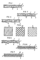
- Figs. l - 3 are sectional views of the first to third embodiments of the laminates;
- Fig. 4 are plan views showing three examples of the patterns of the bonding layer;
- Fig. 5 is a sectional view of the embodiment of Fig. l after heat shrinkage;
- Fig. 6 is a sectional view of the fourth embodiment of the laminate;
- Fig. 7 is a sectional view of the embodiment of Fig. 6 after heat shrinkage;
- Figs. 8 - l0 are sectional views of the fifth to seventh embodiments of the laminate;
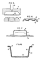
- Fig. ll is a sectional view of the embodiment of Fig. l0 after heat shrinkage;
- Figs. l2 - l4 are sectional views of the eighth to tenth embodiments;
- Fig. l5 is a sectional view of an example of an arrangement for injection molding;
- Fig. l6 is a sectional view of the forming produced by use of the arrangement of Fig. l5;
- Figs. l7 and l8 are sectional views of two examples of the formed casings;
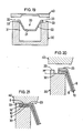
- Fig. l9 is a sectional view of a device for working the flange of the casing of Fig. l8; and
- Figs. 20 and 2l are enlarged sectional views of the device of Fig. l9.
- Referring to Fig. l, a heat-shrinkable laminate l comprises a
film 2 of a heat-shrinkable synthetic resin and ametallic foil 3 bonded to thefilm 2 through abonding layer 4 which is solid with substantially no vacant space. - The heat-shrinkable synthetic resin may be a resin in the polyethylene, polypropylene, vinyl chloride, polystylene or polyester series. Biaxially oriented one is preferable. They will shrink at a temperature of about l00°C to about l60°C. It should preferably have a large shrinkage percentage of at least 50 % (measured by immersing in water at l00°C for 30 seconds). The film may consist of a single layer or two or more layers laminated.
- The
metallic foil 3 may be a metal such as aluminum and copper. - The
bonding layer 4 may include a discontinuoussynthetic resin layer 5 and anadhesive layer 6. It may be formed either by applying a synthetic resin on themetallic foil 3 discontinuously or at intervals to form asynthetic resin layer 5, applying an adhesive over the whole surface to form anadhesive layer 6, and bonding the heat-shrinkable film 2, or by forming theresin layer 5 on themetallic foil 3, applying an adhesive on the whole surface of the heat-shrinkable film 2 to form theadhesive layer 6, and bonding thefilm 2 and themetallic foil 3 together. - Instead of using an adhesive, the films may be bonded by hot bonding or ultrasonic bonding.
- As shown in Fig. 2, the
synthetic resin layer 5 may be formed on the heat-shrinkable film 2. Also, as shown in Fig. 3, thesynthetic resin layer 5 and theadhesive layer 6 may be formed so as to alternate with each other. - The
synthetic resin layer 5 may be of a thermoplastic synthetic resin which has a sufficient fluidity at a temperature during heat treatment of the heat-shrinkable film 2 and which should be adhesive at normal temperature, but non-adhesive at a temperature for heat treatment. Vinyl resin, urethane resin, acryl resin, polyamide resin or silicone resin, or mixture thereof may be used. Acryl resin is particularly preferable. The synthetic resin may be applied in any desired pattern as shown in Fig. 4 to form thelayer 5 which is discontinuous in section in a plurality of directions. - For the
adhesive layer 6, an adhesive should be selected which will not flow at the temperature during heat treatment and can bond firmly thefilm 2 and themetallic foil 3 together. A two-fluid curing-type adhesive such as ones in the polyurethane series is preferable, but a thermoplastic adhesive may be used. - When the laminate l is subjected to heat treatment, the heat-
shrinkable film 2 will shrink. Themetallic foil 3 will wrinkle at the resin layers 5, as shown in Fig. 5, thefilm 2 is not bonded there to themetallic foil 3. But, themetallic foil 3 will not wrinkle at thelayers 6 because thefilm 2 is bonded firmly to themetallic foil 3. Air cannot invade thediscontinuous resin layer 5 because it is filled with resin. - Referring to Fig. 6, the heat-shrinkable
synthetic resin films metallic foil 3 through the bonding layers 4, 4′. Thefilms - A printed layer or a colored layer may be formed on one or both surfaces of the
metallic foil 3. - When the heat-shrinkable laminate l shown in Fig. 6 thus obtained is heated, the
films - Referring to Fig. 8, the heat-shrinkable laminate l comprises a layer 7 of a thermoplastic synthetic resin having a
metallic foil 3 laminated thereto, and afilm 2 of a heat-shrinkable synthetic resin laminated to the layer 7 through thebonding layer 4. - The thermoplastic synthetic resin may be polyethylene, polypropylene, vinyl chloride, polystylene, acryl, polyethyleneterephthalate, or ethylene-vinyl acetate copolymer. Biaxially oriented polypropylene and polyvinyl chloride are preferable. The layer 7 may be either a single layer or a laminate of two or more layers.
- The
metallic foil 3 may be laminated to the synthetic resin layer 7 by any desired method such as coating, extrusion or bonding. - Referring to Fig. 9, the heat-shrinkable laminate l comprises the
metallic foil 3, the synthetic resin layers 7 laminated to both sides of themetallic foil 3, and thefilm 2 of a heat-shrinkable synthetic resin laminated to one of the synthetic resin layers 7 through thebonding layer 4. - Referring to Fig. l0, the heat-shrinkable laminate l comprises the
metallic foil 3, the synthetic resin layers 7 laminated to both sides of themetallic foil 3, and thefilms bonding layer - When the laminate l of Fig. l0 is heated, the
films films films metallic foil 3, too, will shrink. Fig. ll shows the laminate l of Fig. l0 after heated for shrinkage into the heat-shrunk laminate l0. - Referring to Fig. l2, the laminate l0 thus formed may be used as it is, or a
layer 8 of a thermoplastic synthetic resin may be laminated to one side of the laminate l0 having fine wrinkles thereon, by extrusion or hot pressing, or by use of an adhesive. Thelayer 8 serves as a reinforcing layer, as a sealant, and as a decorative layer according to the application. - The thermoplastic synthetic resin may or may not be the same enumerated for the layer 7.
- Referring to Fig. l3, the
synthetic resin layers 8 may be provided on both sides of the heat-shrunk laminate l0. The resin layer may be either a single layer or a laminate consisting of two or more layers, as shown in Fig. l4. Numeral 9 designates an adhesive layer for bonding the resin layers 8 to the laminate l0. As the adhesive, an adhesive in the vinyl or urethane series should be used for bonding materials in the vinyl series. An adhesive in the polyurethane series should be used for bonding materials in the polypropylene series. An adhesive is preferable which assures a secure bonding and has some degree of thermoplasticity. - Referring to Figs. l5 and l6, the heat-shrunk and wrinkled laminate l0 is inserted between dies ll and l2 and the dies are pressed together. Molten thermoplastic synthetic resin is then poured through a nozzle l3. Fig. l6 shows a forming l6 taken out after cooling and solidification. The forming l6 has a layer l4 of poured synthetic resin. It may be formed in any desired shape.
- A casing l7 as shown in Fig. l7 can be produced by forming the laminate l0. Letter A designates an electronic part and numeral l5 does a base plate.
- Fig. l8 shows another example of casing 20 produced by forming the laminate l0 by vacuum forming or pressure forming. The
casing 20 has a bottom wall 2l, aside wall 22, and aflange 23. The casing can be produced in any shape such as round, oval or polygonal. Theflange 23 can be omitted. - As shown in Fig. l9, such a
casing 20 is mounted on abearer 30, which is formed with a recess 3l to receive thecasing 20 with itsflange 23 on a supportingportion 32 of thebearer 30. A slightly higher portion on top of thebearer 30 provides astopper 33, the height H of which is smaller than the thickness of theflange 23 of thecasing 20. - Over the
bearer 30, there is aheating plate 40. When the upper surface of theflange 23 of thecasing 20 is pressurized and heated with this device, thethermoplastic resin layer flange 23 and uniting with the other thermoplastic resin layer. Conveniently, thebearer 30 should be so designed as to be heated to facilitate the uniting of the resin layers 8, 8. Resin may be melted by any other method than direct heating, such as ultrasonic heating or induction heating. - This process is applicable to the heat-shrunk laminate l0 in any of the embodiments in the present invention.
Claims (7)
Applications Claiming Priority (8)
| Application Number | Priority Date | Filing Date | Title |
|---|---|---|---|
| JP24245485A JPS62101436A (en) | 1985-10-28 | 1985-10-28 | Heat-shrinkable laminated sheet |
| JP242454/85 | 1985-10-28 | ||
| JP61039393A JP2514187B2 (en) | 1986-02-24 | 1986-02-24 | Container manufacturing method |
| JP39393/86 | 1986-02-24 | ||
| JP61082463A JPH0760957B2 (en) | 1986-04-08 | 1986-04-08 | Electromagnetic shield casing |
| JP82463/86 | 1986-04-08 | ||
| JP61158312A JPH07102643B2 (en) | 1986-07-03 | 1986-07-03 | Molding sheet and molded article using the sheet |
| JP158312/86 | 1986-07-03 |
Publications (3)
| Publication Number | Publication Date |
|---|---|
| EP0220720A2 true EP0220720A2 (en) | 1987-05-06 |
| EP0220720A3 EP0220720A3 (en) | 1988-12-14 |
| EP0220720B1 EP0220720B1 (en) | 1991-01-23 |
Family
ID=27460752
Family Applications (1)
| Application Number | Title | Priority Date | Filing Date |
|---|---|---|---|
| EP19860114980 Expired - Lifetime EP0220720B1 (en) | 1985-10-28 | 1986-10-28 | Laminates and forms made from the same |
Country Status (3)
| Country | Link |
|---|---|
| US (2) | US4767673A (en) |
| EP (1) | EP0220720B1 (en) |
| DE (1) | DE3677131D1 (en) |
Cited By (6)
| Publication number | Priority date | Publication date | Assignee | Title |
|---|---|---|---|---|
| EP0248398A2 (en) * | 1986-06-04 | 1987-12-09 | Helio Folien GmbH | Packaging bag |
| EP0352729A2 (en) * | 1988-07-27 | 1990-01-31 | Toyo Aluminium Kabushiki Kaisha | Sheet for forming article having electromagnetic wave shieldability |
| EP0668830A1 (en) * | 1992-10-06 | 1995-08-30 | Williams International Corporation | Self tooling, molded electronics packaging |
| DE29619576U1 (en) * | 1996-11-12 | 1997-01-09 | Henkel Kgaa | Geomembranes |
| EP1568799A1 (en) * | 2002-12-03 | 2005-08-31 | The Furukawa Electric Co., Ltd. | Metal material for electric electronic component |
| WO2008113808A2 (en) * | 2007-03-19 | 2008-09-25 | Nokia Corporation | A casing wall for an apparatus |
Families Citing this family (22)
| Publication number | Priority date | Publication date | Assignee | Title |
|---|---|---|---|---|
| US4767673A (en) * | 1985-10-28 | 1988-08-30 | Toyo Aluminium Kabushiki Kaisha | Laminates and formings made from the same |
| JPH01244440A (en) * | 1988-03-25 | 1989-09-28 | Brother Ind Ltd | Image forming device |
| US4874226A (en) * | 1988-04-15 | 1989-10-17 | Mcdonald Kevin | License plate lenses |
| US5342465A (en) * | 1988-12-09 | 1994-08-30 | Trw Inc. | Viscoelastic damping structures and related manufacturing method |
| US5302344A (en) * | 1990-10-31 | 1994-04-12 | Brandeis University | Method for containment of a laboratory chemical |
| US5110668A (en) * | 1990-12-21 | 1992-05-05 | General Electric Company | Flexible laminate having copolyetherester adhesive |
| US5516847A (en) * | 1991-09-03 | 1996-05-14 | Lisco, Inc. | Golf ball cover having an ionic copolymer/non-ionic copolymer blend |
| AU675642B2 (en) * | 1993-02-11 | 1997-02-13 | Telefonaktiebolaget Lm Ericsson (Publ) | A flexible device for encapsulating electronic components |
| US5557064A (en) * | 1994-04-18 | 1996-09-17 | Motorola, Inc. | Conformal shield and method for forming same |
| US5491017A (en) * | 1994-10-14 | 1996-02-13 | Transhield, Inc. | Shrink wrap material and method for protecting articles |
| JP3235943B2 (en) * | 1995-02-06 | 2001-12-04 | 黒田 暢夫 | Method for producing decorative piece made of thermoplastic synthetic resin sheet |
| US5693407A (en) * | 1996-01-05 | 1997-12-02 | Swanson, Jr.; Stanley R. | Flexible transparent holographic laminate |
| TW417025B (en) * | 1997-04-10 | 2001-01-01 | Sumitomo Chemical Co | Front plate for plasma display |
| EP1044101B1 (en) * | 1997-12-31 | 2005-04-27 | Textron Systems Corporation | Metallized sheeting, composites, and methods for their formation |
| TW496823B (en) * | 1998-12-23 | 2002-08-01 | Dung-Han Juang | Process for manufacturing an electromagnetic interference shielding superplastic alloy foil cladded plastic outer shell product |
| EP1219401A3 (en) * | 2000-12-29 | 2004-02-04 | Nokia Corporation | Resin injection molded article with reinforcing or decorative core |
| DE10205458A1 (en) * | 2002-02-08 | 2003-08-28 | Sig Combibloc Sys Gmbh | Process for sterilizing a product packaged in a package |
| NL1025282C2 (en) † | 2004-01-19 | 2005-07-20 | Shieltronics B V | Method for producing container parts, container parts, method for producing a multi-layer film, multi-layer film. |
| JP5257180B2 (en) * | 2008-11-19 | 2013-08-07 | 住友電装株式会社 | Wire protection material |
| FR2940588B1 (en) * | 2008-12-19 | 2011-01-07 | St Microelectronics Grenoble | SURFACE ASSEMBLED MULTICOMPONENT ASSEMBLY |
| JP6626258B2 (en) * | 2014-04-07 | 2019-12-25 | 昭和電工パッケージング株式会社 | Manufacturing method of laminate exterior material |
| JP6372320B2 (en) * | 2014-11-19 | 2018-08-15 | 日立金属株式会社 | Coaxial cable and medical cable using the same |
Citations (2)
| Publication number | Priority date | Publication date | Assignee | Title |
|---|---|---|---|---|
| US3655502A (en) * | 1967-05-09 | 1972-04-11 | Yutaka Yoshikawa | Heat insulating laminate |
| GB1557930A (en) * | 1977-03-16 | 1979-12-19 | Mitsubishi Plastics Ind | Meat shrinkable laminate film |
Family Cites Families (7)
| Publication number | Priority date | Publication date | Assignee | Title |
|---|---|---|---|---|
| US2876067A (en) * | 1955-09-09 | 1959-03-03 | Du Pont | Heat-shrinkable film |
| GB1088555A (en) * | 1964-08-17 | 1967-10-25 | Smith & Nephew Plastics | Improvements in and relating to laminates and methods for their manufacture |
| CH441730A (en) * | 1966-08-09 | 1967-08-15 | Chemie Ind Investment Ag | Plastic composite material, process for its production and use of the plastic composite material |
| US3874966A (en) * | 1973-03-28 | 1975-04-01 | Johns Manville | Laminated article of manufacture and method of making the same |
| US4378393A (en) * | 1978-09-22 | 1983-03-29 | High Voltage Engineering Corporation | Heat-shrinkable article |
| JPS588535Y2 (en) * | 1979-04-20 | 1983-02-16 | 日東電工株式会社 | heat shrinkable articles |
| US4767673A (en) * | 1985-10-28 | 1988-08-30 | Toyo Aluminium Kabushiki Kaisha | Laminates and formings made from the same |
-
1986
- 1986-10-27 US US06/923,548 patent/US4767673A/en not_active Expired - Fee Related
- 1986-10-28 DE DE8686114980T patent/DE3677131D1/en not_active Expired - Fee Related
- 1986-10-28 EP EP19860114980 patent/EP0220720B1/en not_active Expired - Lifetime
-
1988
- 1988-07-01 US US07/214,358 patent/US4868033A/en not_active Expired - Fee Related
Patent Citations (2)
| Publication number | Priority date | Publication date | Assignee | Title |
|---|---|---|---|---|
| US3655502A (en) * | 1967-05-09 | 1972-04-11 | Yutaka Yoshikawa | Heat insulating laminate |
| GB1557930A (en) * | 1977-03-16 | 1979-12-19 | Mitsubishi Plastics Ind | Meat shrinkable laminate film |
Cited By (12)
| Publication number | Priority date | Publication date | Assignee | Title |
|---|---|---|---|---|
| EP0248398A2 (en) * | 1986-06-04 | 1987-12-09 | Helio Folien GmbH | Packaging bag |
| EP0248398A3 (en) * | 1986-06-04 | 1989-02-01 | Helio Folien GmbH | Packaging bag |
| EP0352729A2 (en) * | 1988-07-27 | 1990-01-31 | Toyo Aluminium Kabushiki Kaisha | Sheet for forming article having electromagnetic wave shieldability |
| EP0352729A3 (en) * | 1988-07-27 | 1990-07-25 | Toyo Aluminium Kabushiki Kaisha | Sheet for forming article having electromagnetic wave shieldability |
| EP0668830A1 (en) * | 1992-10-06 | 1995-08-30 | Williams International Corporation | Self tooling, molded electronics packaging |
| EP0668830A4 (en) * | 1992-10-06 | 1997-03-26 | Williams Int Corp | Self tooling, molded electronics packaging. |
| DE29619576U1 (en) * | 1996-11-12 | 1997-01-09 | Henkel Kgaa | Geomembranes |
| EP1568799A1 (en) * | 2002-12-03 | 2005-08-31 | The Furukawa Electric Co., Ltd. | Metal material for electric electronic component |
| EP1568799A4 (en) * | 2002-12-03 | 2008-12-17 | Furukawa Electric Co Ltd | Metal material for electric electronic component |
| WO2008113808A2 (en) * | 2007-03-19 | 2008-09-25 | Nokia Corporation | A casing wall for an apparatus |
| WO2008113808A3 (en) * | 2007-03-19 | 2008-12-18 | Nokia Corp | A casing wall for an apparatus |
| US9056430B2 (en) | 2007-03-19 | 2015-06-16 | Vertu Corporation Limited | Casing wall for an apparatus |
Also Published As
| Publication number | Publication date |
|---|---|
| US4767673A (en) | 1988-08-30 |
| EP0220720B1 (en) | 1991-01-23 |
| DE3677131D1 (en) | 1991-02-28 |
| US4868033A (en) | 1989-09-19 |
| EP0220720A3 (en) | 1988-12-14 |
Similar Documents
| Publication | Publication Date | Title |
|---|---|---|
| EP0220720B1 (en) | Laminates and forms made from the same | |
| JP3142554B2 (en) | Multilayer films and laminates for printed circuit board manufacture | |
| KR930000144B1 (en) | Release film composed of laminate | |
| EP1618046B1 (en) | Blister pack | |
| KR20000017319A (en) | Sealed containers with tabs and method of making the same | |
| JP2000502014A (en) | Packaging container | |
| CN101253045A (en) | Method of laminating adherend | |
| KR20150028718A (en) | Container for food and method of manufacturing the same | |
| EP0909639A4 (en) | Multilayered laminate containing ultrahigh-molecular polyolefin layer, process for producing the same, and apparatus for producing the multilayered laminate | |
| MY136428A (en) | Resin/copper/metal laminate and method of producing same | |
| JP6863523B2 (en) | Manufacturing method of release film and molded product | |
| TW201736117A (en) | Laminated packing material having a metal foil, an insulating layer, a heat-sealable resin layer, and a protective layer to be thin and achieving no reduced formability | |
| CN100464966C (en) | Stretched film and method for production thereof | |
| CN1325247C (en) | Separating plate-composite component for producing printed circuit board components and method for producing a composite component of this type | |
| JPS63290739A (en) | Decorative-film forming multilayer composite material for packaging material, arranging method of such composite material and packaging material obtained through said method | |
| CA2426801C (en) | Plastic film | |
| JPH0244552Y2 (en) | ||
| JPS6313739A (en) | Sheet for molding and molded form using said sheet | |
| OA12410A (en) | Plastic film. | |
| JP4319729B2 (en) | Cooling container and manufacturing method thereof | |
| JP2514187B2 (en) | Container manufacturing method | |
| JPH04201443A (en) | Cushioning material | |
| JP2525649Y2 (en) | Sheet for PTP packaging | |
| JPS62237360A (en) | Electromagnetic wave shield casing | |
| JPH04219229A (en) | High-strength laminate of mutually tight-adhered thermal plastic resin stretched films and its manufacturing technique |
Legal Events
| Date | Code | Title | Description |
|---|---|---|---|
| PUAI | Public reference made under article 153(3) epc to a published international application that has entered the european phase |
Free format text: ORIGINAL CODE: 0009012 |
|
| 17P | Request for examination filed |
Effective date: 19861028 |
|
| AK | Designated contracting states |
Kind code of ref document: A2 Designated state(s): CH DE GB LI SE |
|
| PUAL | Search report despatched |
Free format text: ORIGINAL CODE: 0009013 |
|
| RHK1 | Main classification (correction) |
Ipc: B32B 27/08 |
|
| AK | Designated contracting states |
Kind code of ref document: A3 Designated state(s): CH DE GB LI SE |
|
| 17Q | First examination report despatched |
Effective date: 19900226 |
|
| GRAA | (expected) grant |
Free format text: ORIGINAL CODE: 0009210 |
|
| AK | Designated contracting states |
Kind code of ref document: B1 Designated state(s): CH DE GB LI SE |
|
| REF | Corresponds to: |
Ref document number: 3677131 Country of ref document: DE Date of ref document: 19910228 |
|
| PLBE | No opposition filed within time limit |
Free format text: ORIGINAL CODE: 0009261 |
|
| STAA | Information on the status of an ep patent application or granted ep patent |
Free format text: STATUS: NO OPPOSITION FILED WITHIN TIME LIMIT |
|
| 26N | No opposition filed | ||
| PGFP | Annual fee paid to national office [announced via postgrant information from national office to epo] |
Ref country code: GB Payment date: 19941010 Year of fee payment: 9 |
|
| PGFP | Annual fee paid to national office [announced via postgrant information from national office to epo] |
Ref country code: SE Payment date: 19941021 Year of fee payment: 9 |
|
| PGFP | Annual fee paid to national office [announced via postgrant information from national office to epo] |
Ref country code: CH Payment date: 19941121 Year of fee payment: 9 |
|
| PGFP | Annual fee paid to national office [announced via postgrant information from national office to epo] |
Ref country code: DE Payment date: 19941223 Year of fee payment: 9 |
|
| EAL | Se: european patent in force in sweden |
Ref document number: 86114980.5 |
|
| PG25 | Lapsed in a contracting state [announced via postgrant information from national office to epo] |
Ref country code: GB Effective date: 19951028 |
|
| PG25 | Lapsed in a contracting state [announced via postgrant information from national office to epo] |
Ref country code: SE Effective date: 19951029 |
|
| PG25 | Lapsed in a contracting state [announced via postgrant information from national office to epo] |
Ref country code: LI Effective date: 19951031 Ref country code: CH Effective date: 19951031 |
|
| REG | Reference to a national code |
Ref country code: CH Ref legal event code: PL |
|
| GBPC | Gb: european patent ceased through non-payment of renewal fee |
Effective date: 19951028 |
|
| EUG | Se: european patent has lapsed |
Ref document number: 86114980.5 |
|
| PG25 | Lapsed in a contracting state [announced via postgrant information from national office to epo] |
Ref country code: DE Effective date: 19960702 |