EP0220700A2 - Insertion system for control and/or power supply voltages in a coaxial cable for radio-frequency - Google Patents
Insertion system for control and/or power supply voltages in a coaxial cable for radio-frequency Download PDFInfo
- Publication number
- EP0220700A2 EP0220700A2 EP86114837A EP86114837A EP0220700A2 EP 0220700 A2 EP0220700 A2 EP 0220700A2 EP 86114837 A EP86114837 A EP 86114837A EP 86114837 A EP86114837 A EP 86114837A EP 0220700 A2 EP0220700 A2 EP 0220700A2
- Authority
- EP
- European Patent Office
- Prior art keywords
- power supply
- control
- injector
- fact
- coaxial cable
- Prior art date
- Legal status (The legal status is an assumption and is not a legal conclusion. Google has not performed a legal analysis and makes no representation as to the accuracy of the status listed.)
- Withdrawn
Links
Images

Classifications
-
- H—ELECTRICITY
- H03—ELECTRONIC CIRCUITRY
- H03H—IMPEDANCE NETWORKS, e.g. RESONANT CIRCUITS; RESONATORS
- H03H7/00—Multiple-port networks comprising only passive electrical elements as network components
- H03H7/46—Networks for connecting several sources or loads, working on different frequencies or frequency bands, to a common load or source
- H03H7/461—Networks for connecting several sources or loads, working on different frequencies or frequency bands, to a common load or source particularly adapted for use in common antenna systems
Definitions
- the invention relates to an insertion system for power supply and/or control voltages , deriving from a power supply and/or control box or from a power pack, in a coaxial cable for radio-frequency.
- connection of the control and/or power supply box to the remainder of the system is usually achieved by means of a twin-wire or bipolar conductor, suitable for delivering the power supply of the electric network,and two coaxial cables, of which : one directed towards the amplification, switching, conversion or rotation equipment placed in the vicinity of the aerials and/or various radio-television systems ; and the other directed to the receiver.
- twin-wire or bipolar conductor suitable for delivering the power supply of the electric network
- two coaxial cables of which : one directed towards the amplification, switching, conversion or rotation equipment placed in the vicinity of the aerials and/or various radio-television systems ; and the other directed to the receiver.
- the first defect may be attributed to the fact that the installation and placing of the coaxial cables in the above- mentioned installations always proves to be tiresome and difficult due to their non-flexibility deriving from the magnitude of their diameter, in the range of roughly 7 MM, required to avoid excessive attenuation of the signals which pass through them, especially over long runs.
- the aim of the present invention is to eliminate the drawbacks mentioned beforehand and, at the same time, to avoid considerable signal losses, or external interferences which affect the signals transiting in the coaxial cable.
- the invention solves the problem by means of an insertion system of power supply and/or control voltages deriving from a power supply and/or control box or from a power pack, in a coaxial cable for radio-frequency.
- the injector or R.F. filter is realized separately from the power supply and switching box and is connected to it through a bipolar conductor ; since the injector is detached from the control or power supply box, the two traditional coaxial cables, for transmission of the radio-frequency signals, are no longer connected to the box; the injector or R.F. filter may be directly inserted in the R.F. input connectors of the receivers, in the aerial plugs or connectors of the equipment or at any point in series on the coaxial cable between receivers and amplifier, switching, convertor or rotation devices and the like, whereas its power is obtained either directly from the power supply and/or control box or from a power pack by means of an ordinary electrical bipolar conductor.
- the advantages obtained from using the present invention consist mainly in the fact that it is possible to insert onto a coaxial cable for radio-frequency the power supply and/or control voltage(s) deriving from an ordinary power supply and/ or control box, by means of a simple injector and a common bipolar conductor, regardless of the fact that these signals are continuous, with varying, alternating voltage and/or polarity, with pulses or impulse trains ; by using the injector one avoids, moreover, employment of over-long coaxial cables for radio-frequency for the connection of the control and/or power supply boxes to the installations, without affecting or attenuating to any noticeable degree the R.F. signals transiting therein, and the injector may be equipped with connectors for the coaxial cable with screw clamps or coaxial plugs which may be fitted to the various standard connectors on the market.
- Another advantage consists in the fact that the separation of the above mentioned components permits easy installation and positioning of the power supply and/or control boxes of any device which must be powered or controlled by means of a coaxial cable, such as, for example : R.F. amplifiers, convertors, switching systems; rotors for aerials and the like.
- These power supply and/or control boxes may be placed either near or far from the receiving equipment or from the plugs or connectors of the instruments' aerials or also from the line in coaxial cable.
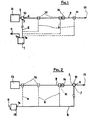
- the figures show the means to accomplish an insertion system of power supply and/or control voltages, deriving from a power supply and/or control box or from a power pack, in a coaxial cable for radio-frequency, mainly consisting of (1) a power supply and control box which supplies the power supply and control voltages to the injector, or R. F. filter (10) through its output (lb).
- the control box or power pack (1) is connected to the electric network through its input (lA) and the current tap (11).
- the power pack (1) and the tap (11) may be incorporated in one single unit (12), as may be seen in Figure 2.
- the power pack (1) may be of any known type.
- the radio-frequency filter (10) which from now on will be called preferably "injector”, receives on its input (7) all the power supply and control voltages sent by the power pack (1) by means of a normal electric bipolar conductor (8).
- the injector (10) transmits said voltages to the other parts of the system, preventing the passage of said voltages onto the connector (3) directed towards the receiving apparatus (13).
- the injector (10) permits passage of the R.F. signals between the connectors 2 and 3, thus impeding the trans- . it from the input 7.
- FIG 3 shows an injector (10) according to its preferred but not restrictive construction version, which may be directly inserted into the coaxial input connector of a radio/television receiver 13. It is contained in an outer casing (14) made of conductive material, screening the radio-frequency in such a way as to avoid external R.F. interferences. The presence of said casing (14), though preferable, is, nonetheless, not indispensable for the correct functioning of the injector (10).
- the coaxial connector used for connecting with the coaxial cable (9) deriving from the amplifying circuits, attenuators, R.F. convertors or from the mobile directional devices applied to the aerials, not indicated in figures 1 and 2, but present beyond the arrow 15.
- the coaxial connection 3 is on the other hand used at the input of any type of receiving apparatus 13.
- the capacitor 4 presents a very low impedance for R.F. and an infinite impedance (open circuit) for direct current and/or low frequency.
- the numeral 5 indicates an impedance and N°6 a feedthrough capacitor, which are able to block the transit of R.F. from the connection 2 to the input 7, and vice-versa, without interfering with or noticeably attenuating the transit of the R.F. signals, through the connectors 2 and 3.
- the input 7 for the control and power supply voltages is connected to the power pack 1 by means of a simple bipolar conductor 8 of reduced dimensions, (for example 2 x 0.5 mmg) one end of which is connected to the container 14, or ground of the injector 10.
- FIG 4 shows an injector 10, according to an alternative but not restrictive construction version, which may be applied directly to the plugs or connections 16 present in dwellings,or in the vicinity of each apparatus.
- This solution differs from the former merely by the fact that the coaxial connectors 2 and 3 have the male and female taps inverted.
- the numerals 2A and 3A show how the connections 2 and 3 may possibly be arranged in an axial direction.
- the injector 10 may be positioned at any point between the receiving apparatus 13 and the amplifier circuits or devices, attenuators, R.F. converters and/or mobile directional devices which may be applied to the aerials, present beyond the arrow marked by N° 15 in figures 1 and 2.
- the injector 10 has the same characteristics, even if, instead of the coaxial connectors 2 and 3 use is made of normal screw clamps.
- Figure 5 shows the electrical diagram corresponding to the injector 10. Judging from the former description it is evident that the system makes application of the devices to all types of installation far easier, swifter, more economical and functional. Moreover, it is important to point out that a connector may be attached,respectively, on the input 7 and/or on the output 1B (to which is connected the common electrical bipolar conductor 8), to the injector 10 and/or to the power supply and control box, or power pack 1 or 12, in such a way as to obtain the easy and rapid interchangeability of said injector 10 and/or the type of power pack 1 or 12.
- this system has the essential property of being able to allow positioning of the box comprising the power pack 1, to be used for feeding and/or controlling any type of device which must be fed or controlled through a coaxial cable such as, for example, R.F. amplifiers, convertors, switching systems, rotors for aerials and the like, near to or far from the receiver apparatus 13 or from the plug or aerial connector 16 or from the line in coaxial cable for R.F. 9, merely by shortening or lengthening the common bipolar conductor 8 which connects the injector 10 to the box 1 or 12.
- a coaxial cable such as, for example, R.F. amplifiers, convertors, switching systems, rotors for aerials and the like
Landscapes
- Input Circuits Of Receivers And Coupling Of Receivers And Audio Equipment (AREA)
- Coupling Device And Connection With Printed Circuit (AREA)
Abstract
An insertion system of power supply and/or control voltages, deriving from a power supply and/or control box, in a coaxial cable for radio-frequency, comprising an injector or R.F. fitter (10), equipped with plugs (2) and (3) or clamps, which is applied in series at any point on the coaxial cable (9) included between a receiver (13) and an amplifier, selectors, converter, and/or aerial directional devices and the like.
The injector (10) is coupled to a control and/or power supply box (1) by means of a simple bipolar conductor (8) through which transit only the control and/or power supply voltages, either in the form of continuous signals, or in the form of possible continuous or alternating power supply voltages, coupled or not to pulsed control voltages or with pulse trains overlapping the power supply voltages, coded or not, which may be used for other purposes.
Description
- The invention relates to an insertion system for power supply and/or control voltages , deriving from a power supply and/or control box or from a power pack, in a coaxial cable for radio-frequency.
- As is known, in the present radio/television reception installations, connection of the control and/or power supply box to the remainder of the system is usually achieved by means of a twin-wire or bipolar conductor, suitable for delivering the power supply of the electric network,and two coaxial cables, of which : one directed towards the amplification, switching, conversion or rotation equipment placed in the vicinity of the aerials and/or various radio-television systems ; and the other directed to the receiver. These installations, though valid from a functional point of view, do, however, manifest certain particular defects. The first defect may be attributed to the fact that the installation and placing of the coaxial cables in the above- mentioned installations always proves to be tiresome and difficult due to their non-flexibility deriving from the magnitude of their diameter, in the range of roughly 7 MM, required to avoid excessive attenuation of the signals which pass through them, especially over long runs.
- Another drawback is due to the fact that said coaxial cables, arranged haphazardly in the installations placed inside private abodes, necessarily remain in sight, thus creating a decidely false note in the surrounding environment.
- In the same way, positioning of the power supply and/or control boxes, especially in the immediate vicinity of radio/ television receivers proves to be particularly inconvenient, difficult and anti-aesthetic.
- The aim of the present invention is to eliminate the drawbacks mentioned beforehand and, at the same time, to avoid considerable signal losses, or external interferences which affect the signals transiting in the coaxial cable.
- The invention, such as it is characterized in the claims, solves the problem by means of an insertion system of power supply and/or control voltages deriving from a power supply and/or control box or from a power pack, in a coaxial cable for radio-frequency.
- By means of the use of a system of this type, the following results are obtained : the injector or R.F. filter is realized separately from the power supply and switching box and is connected to it through a bipolar conductor ; since the injector is detached from the control or power supply box, the two traditional coaxial cables, for transmission of the radio-frequency signals, are no longer connected to the box; the injector or R.F. filter may be directly inserted in the R.F. input connectors of the receivers, in the aerial plugs or connectors of the equipment or at any point in series on the coaxial cable between receivers and amplifier, switching, convertor or rotation devices and the like, whereas its power is obtained either directly from the power supply and/or control box or from a power pack by means of an ordinary electrical bipolar conductor.
- The advantages obtained from using the present invention, consist mainly in the fact that it is possible to insert onto a coaxial cable for radio-frequency the power supply and/or control voltage(s) deriving from an ordinary power supply and/ or control box, by means of a simple injector and a common bipolar conductor, regardless of the fact that these signals are continuous, with varying, alternating voltage and/or polarity, with pulses or impulse trains ; by using the injector one avoids, moreover, employment of over-long coaxial cables for radio-frequency for the connection of the control and/or power supply boxes to the installations, without affecting or attenuating to any noticeable degree the R.F. signals transiting therein, and the injector may be equipped with connectors for the coaxial cable with screw clamps or coaxial plugs which may be fitted to the various standard connectors on the market.
- Another advantage consists in the fact that the separation of the above mentioned components permits easy installation and positioning of the power supply and/or control boxes of any device which must be powered or controlled by means of a coaxial cable, such as, for example : R.F. amplifiers, convertors, switching systems; rotors for aerials and the like.
- These power supply and/or control boxes may be placed either near or far from the receiving equipment or from the plugs or connectors of the instruments' aerials or also from the line in coaxial cable.
- To understand the present invention better, it will be explained in greater detail in the following description with reference to the appended drawings, which represent some illustrative but not restricted embodiments of the present invention, in which :
- Figures 1 and 2 show functional diagrams of receiving apparatus using the system described in the present invention ;
- Figures 3 and 4 show a schematic view of two construction models of two types of injectors or R.F. filters and,
- figure 5 represents a preferred but not restrictive embodiment of an electric diagram corresponding to the injectors or R.F. filters illustrated in figures 3 and 4.
- The figures show the means to accomplish an insertion system of power supply and/or control voltages, deriving from a power supply and/or control box or from a power pack, in a coaxial cable for radio-frequency, mainly consisting of (1) a power supply and control box which supplies the power supply and control voltages to the injector, or R. F. filter (10) through its output (lb).
- · The control box or power pack (1) is connected to the electric network through its input (lA) and the current tap (11). As an alternative, the power pack (1) and the tap (11) may be incorporated in one single unit (12), as may be seen in Figure 2. In any case, the power pack (1) may be of any known type. The radio-frequency filter (10), which from now on will be called preferably "injector", receives on its input (7) all the power supply and control voltages sent by the power pack (1) by means of a normal electric bipolar conductor (8). Through the connector (2) and the coaxial cable (9), the injector (10) transmits said voltages to the other parts of the system, preventing the passage of said voltages onto the connector (3) directed towards the receiving apparatus (13). At the same time, the injector (10) permits passage of the R.F. signals between the
connectors input 7. - Figure 3 shows an injector (10) according to its preferred but not restrictive construction version, which may be directly inserted into the coaxial input connector of a radio/
television receiver 13. It is contained in an outer casing (14) made of conductive material, screening the radio-frequency in such a way as to avoid external R.F. interferences. The presence of said casing (14), though preferable, is, nonetheless, not indispensable for the correct functioning of the injector (10). By thenumeral 2 is indicated the coaxial connector used for connecting with the coaxial cable (9) deriving from the amplifying circuits, attenuators, R.F. convertors or from the mobile directional devices applied to the aerials, not indicated in figures 1 and 2, but present beyond thearrow 15. Thecoaxial connection 3 is on the other hand used at the input of any type of receivingapparatus 13. Thecapacitor 4 presents a very low impedance for R.F. and an infinite impedance (open circuit) for direct current and/or low frequency. Thenumeral 5 indicates an impedance and N°6 a feedthrough capacitor, which are able to block the transit of R.F. from theconnection 2 to theinput 7, and vice-versa, without interfering with or noticeably attenuating the transit of the R.F. signals, through theconnectors input 7 for the control and power supply voltages is connected to the power pack 1 by means of a simplebipolar conductor 8 of reduced dimensions, (for example 2 x 0.5 mmg) one end of which is connected to thecontainer 14, or ground of theinjector 10. - Figure 4 shows an
injector 10, according to an alternative but not restrictive construction version, which may be applied directly to the plugs orconnections 16 present in dwellings,or in the vicinity of each apparatus. This solution differs from the former merely by the fact that thecoaxial connectors numerals connections injector 10 may be positioned at any point between the receivingapparatus 13 and the amplifier circuits or devices, attenuators, R.F. converters and/or mobile directional devices which may be applied to the aerials, present beyond the arrow marked by N° 15 in figures 1 and 2. - In the same way, the
injector 10 has the same characteristics, even if, instead of thecoaxial connectors injector 10. Judging from the former description it is evident that the system makes application of the devices to all types of installation far easier, swifter, more economical and functional. Moreover, it is important to point out that a connector may be attached,respectively, on theinput 7 and/or on the output 1B (to which is connected the common electrical bipolar conductor 8), to theinjector 10 and/or to the power supply and control box, orpower pack 1 or 12, in such a way as to obtain the easy and rapid interchangeability of saidinjector 10 and/or the type ofpower pack 1 or 12. - Moreover, this system has the essential property of being able to allow positioning of the box comprising the power pack 1, to be used for feeding and/or controlling any type of device which must be fed or controlled through a coaxial cable such as, for example, R.F. amplifiers, convertors, switching systems, rotors for aerials and the like, near to or far from the
receiver apparatus 13 or from the plug oraerial connector 16 or from the line in coaxial cable for R.F. 9, merely by shortening or lengthening the commonbipolar conductor 8 which connects theinjector 10 to thebox 1 or 12.
Claims (9)
1. Insertion system of power supply and/or control voltages, deriving from a power supply and/or control box, or from a power pack, in a coaxial cable for radio-frequency, which comprises an injector, or R.F. filter (10), the input of which (7) is connected to a control and/or power supply box (1) through a common bipolar conductor (8) and the connectors (2) and (3) are attached in series to the coaxial cable (9), deriving from the receiving apparatus.
2. System according to claim 1, characterized by the fact that through the bipolar conductor (8) transit only the control and/or power supply voltages, either in the form of continuous signals with varying voltage and/or polarity, or under the form of possible continuous or alternating power supply voltages coupled or not with pulsed control voltages or with pulse trains overlapping the power supply voltages, coded or not, which may be used for other purposes.
3. System according to claim 1, characterized by the fact that the pairing of injector (10)/control box or power pack (1) comprises an insertion system of control and/or power supply voltages for control apparatus for aerial rotors or for power packs and/or control boxes for aerial equipment.
4. System according to any of the previous claims, characterized by the fact that the injector (10) is directly fed by a power supply and/or control box , or power pack (1), by means of a common electric bipolar conductor, which is flexible, adaptable and of reduced dimensions.
5. System according to any of the former claims, charac― rized by the fact that the injector (10) is equipped with connectors for the coaxial cable (9), with screw clamps or with male or female plugs (2), (3) and (3A) adaptable to standard connectors.
6. System according to any of the previous claims, characterized by the fact that the injector (10) or R.F. filter may be directly inserted : on the R.F. input connectors of the receivers (13) ; in the plugs or aerial connectors (16) of the instruments or at any intermediate point ; in series with the coaxial cable (9), between said receivers (13) and the amplifier, switching, convertor devices and/or aerial rotation devices or other apparatus.
7. System according to any of the former claims, characterized by the fact that the injector (10) is encased or built in a casing made of conductive material to serve as a screen of radio-frequencies, or not.
8. System according to any of the previous claims, characterized by the fact that the injector (10) comprises an R.F. filter of known type.
9. System according to any of the former claims, characterized by the fact that the input (7) of the injector (10) and/or output (1B) of the power supply and control box or power pack (1) or (12) are equipped with connectors in which are plugged the ends of a normal electrical bipolar conductor (8).
Applications Claiming Priority (2)
| Application Number | Priority Date | Filing Date | Title |
|---|---|---|---|
| IT22646/85A IT1186344B (en) | 1985-10-29 | 1985-10-29 | POWER AND / OR COMMAND VOLTAGE INSERTION SYSTEM, COMING FROM A POWER AND / OR COMMAND BOX OR FROM A POWER SUPPLY, IN A COAXIAL CABLE FOR RADIOFREQUENCY |
| IT2264685 | 1985-10-29 |
Publications (2)
| Publication Number | Publication Date |
|---|---|
| EP0220700A2 true EP0220700A2 (en) | 1987-05-06 |
| EP0220700A3 EP0220700A3 (en) | 1989-03-22 |
Family
ID=11198809
Family Applications (1)
| Application Number | Title | Priority Date | Filing Date |
|---|---|---|---|
| EP86114837A Withdrawn EP0220700A3 (en) | 1985-10-29 | 1986-10-24 | Insertion system for control and/or power supply voltages in a coaxial cable for radio-frequency |
Country Status (2)
| Country | Link |
|---|---|
| EP (1) | EP0220700A3 (en) |
| IT (1) | IT1186344B (en) |
Cited By (2)
| Publication number | Priority date | Publication date | Assignee | Title |
|---|---|---|---|---|
| EP0479599A2 (en) * | 1990-10-05 | 1992-04-08 | Nokia Mobile Phones Ltd. | Method and apparatus for controlling switches |
| WO2007059571A1 (en) * | 2005-11-23 | 2007-05-31 | Demdl No. 1 Pty. Ltd. | System and method for distributing electrical power |
Citations (1)
| Publication number | Priority date | Publication date | Assignee | Title |
|---|---|---|---|---|
| FR1442341A (en) * | 1965-02-18 | 1966-06-17 | Syma Sa | Power supply device for antenna amplifiers for receiving radio signals, particularly television |
-
1985
- 1985-10-29 IT IT22646/85A patent/IT1186344B/en active
-
1986
- 1986-10-24 EP EP86114837A patent/EP0220700A3/en not_active Withdrawn
Patent Citations (1)
| Publication number | Priority date | Publication date | Assignee | Title |
|---|---|---|---|---|
| FR1442341A (en) * | 1965-02-18 | 1966-06-17 | Syma Sa | Power supply device for antenna amplifiers for receiving radio signals, particularly television |
Non-Patent Citations (2)
| Title |
|---|
| FUNKSCHAU, vol. 34, no. 19, 1st October 1962, page 511, Munich, DE; "Antennenanlagen mit ferngespeisten Verst{rkern f}r schwierige Empfangslagen" * |
| FUNKSCHAU, vol. 41, no. 12, June 1969, pages 361-363, Munich, DE; J. CONRAD: "Grosse Gemeinschaftsantennen-Anlagen verst{rkt im Kommen" * |
Cited By (3)
| Publication number | Priority date | Publication date | Assignee | Title |
|---|---|---|---|---|
| EP0479599A2 (en) * | 1990-10-05 | 1992-04-08 | Nokia Mobile Phones Ltd. | Method and apparatus for controlling switches |
| EP0479599A3 (en) * | 1990-10-05 | 1993-01-13 | Nokia Mobile Phones Ltd | Method and apparatus for controlling switches |
| WO2007059571A1 (en) * | 2005-11-23 | 2007-05-31 | Demdl No. 1 Pty. Ltd. | System and method for distributing electrical power |
Also Published As
| Publication number | Publication date |
|---|---|
| IT8522646A0 (en) | 1985-10-29 |
| EP0220700A3 (en) | 1989-03-22 |
| IT1186344B (en) | 1987-11-26 |
Similar Documents
| Publication | Publication Date | Title |
|---|---|---|
| US4755776A (en) | Tap device for broadband communications systems | |
| CA2277919C (en) | In-service removable cable ground connection | |
| US6066801A (en) | Cable television/telephone tap | |
| US5053910A (en) | Surge suppressor for coaxial transmission line | |
| US8170479B2 (en) | Apparatus and systems for electrically isolating multiple devices | |
| US5633614A (en) | Unbalanced to balanced signal line coupling device | |
| US6255935B1 (en) | Coupling capacitor having an integrated connecting cable | |
| US4999729A (en) | Satellite receiver protection apparatus | |
| US7012496B2 (en) | Noise elimination device and method for installing the same | |
| EP0050435A2 (en) | Coaxial cable/fiber optic bus network | |
| WO1997047056A1 (en) | Coaxial cable tap | |
| US7701309B2 (en) | Power inserter module | |
| US6710673B1 (en) | Return path noise reducer | |
| EP0220700A2 (en) | Insertion system for control and/or power supply voltages in a coaxial cable for radio-frequency | |
| US4311974A (en) | Wide band directional coupler | |
| EP1521381B1 (en) | Medium-voltage isolated capacitive coupling system | |
| US20030192063A1 (en) | Digital interface unit apparatus and system | |
| US3176230A (en) | Cable connector and signal distribution system for radio receivers | |
| US7039360B2 (en) | External noise intrusion prevention device, signal amplifier, protector and antenna plug | |
| EP0800242A1 (en) | High-frequency signal branching device | |
| KR940009051B1 (en) | Duplex microphone communication system | |
| US3544921A (en) | Signal distribution system comprising a high frequency inductive coupler | |
| US20080129533A1 (en) | Method and system for communicating over neutral power lines | |
| DE3060163D1 (en) | Input circuit for receiver-side line terminal apparatus of a telecommunication system | |
| JP3078498B2 (en) | Signal transmission interface unit and signal transmission network using the same |
Legal Events
| Date | Code | Title | Description |
|---|---|---|---|
| PUAI | Public reference made under article 153(3) epc to a published international application that has entered the european phase |
Free format text: ORIGINAL CODE: 0009012 |
|
| AK | Designated contracting states |
Kind code of ref document: A2 Designated state(s): AT BE CH DE ES FR GB GR LI LU NL SE |
|
| PUAL | Search report despatched |
Free format text: ORIGINAL CODE: 0009013 |
|
| AK | Designated contracting states |
Kind code of ref document: A3 Designated state(s): AT BE CH DE ES FR GB GR LI LU NL SE |
|
| STAA | Information on the status of an ep patent application or granted ep patent |
Free format text: STATUS: THE APPLICATION IS DEEMED TO BE WITHDRAWN |
|
| 18D | Application deemed to be withdrawn |
Effective date: 19881101 |