EP0220644B1 - Vacuum system for combination fold-off control - Google Patents
Vacuum system for combination fold-off control Download PDFInfo
- Publication number
- EP0220644B1 EP0220644B1 EP86114508A EP86114508A EP0220644B1 EP 0220644 B1 EP0220644 B1 EP 0220644B1 EP 86114508 A EP86114508 A EP 86114508A EP 86114508 A EP86114508 A EP 86114508A EP 0220644 B1 EP0220644 B1 EP 0220644B1
- Authority
- EP
- European Patent Office
- Prior art keywords
- signature
- roll
- vacuum
- cylinder
- guide
- Prior art date
- Legal status (The legal status is an assumption and is not a legal conclusion. Google has not performed a legal analysis and makes no representation as to the accuracy of the status listed.)
- Expired
Links
- 239000012141 concentrate Substances 0.000 claims description 3
- 239000000463 material Substances 0.000 description 5
- XEEYBQQBJWHFJM-UHFFFAOYSA-N Iron Chemical compound [Fe] XEEYBQQBJWHFJM-UHFFFAOYSA-N 0.000 description 4
- 230000007246 mechanism Effects 0.000 description 4
- 230000009471 action Effects 0.000 description 2
- 238000009963 fulling Methods 0.000 description 2
- 229910052742 iron Inorganic materials 0.000 description 2
- 230000000694 effects Effects 0.000 description 1
- 230000004048 modification Effects 0.000 description 1
- 238000012986 modification Methods 0.000 description 1
- 230000008707 rearrangement Effects 0.000 description 1
Images


Classifications
-
- B—PERFORMING OPERATIONS; TRANSPORTING
- B65—CONVEYING; PACKING; STORING; HANDLING THIN OR FILAMENTARY MATERIAL
- B65H—HANDLING THIN OR FILAMENTARY MATERIAL, e.g. SHEETS, WEBS, CABLES
- B65H45/00—Folding thin material
- B65H45/12—Folding articles or webs with application of pressure to define or form crease lines
- B65H45/16—Rotary folders
- B65H45/162—Rotary folders with folding jaw cylinders
- B65H45/167—Rotary folders with folding jaw cylinders having associated sheet guide means
Definitions
- This invention relates generally to signature folders for publication presses and the like, and more particularly to a novel and improved system for preventing tail whipping when the direction of movement of a portion of signature is reversed.
- Signature folders for publication presses and the like are well known, see e.g. US-A-2 659 437.
- Such folders often provide a pair of counter-rotating cylinders which define a nip or throat through which the signatures pass during the folding operation.
- Gripping means are provided which grip the signature at spaced locations and cause the intermediate signature portion between such locations to move first along the periphery of one cylinder and then reverse directions and move along the periphery of the other cylinder.
- vacuum means is provided to create a vacuum between guide means and a signature portion as defined in claim 1.
- Such vacuum removes the air cushion along one side of the signature tail and the pressure along the other side of the signature tail tends to press the signature tail over against a perforated vacuum roll. This prevents the initial whipping action.
- the vacuum roll is journaled within the zone between the two cylinders and below the throat.
- Such roll is freely journaled on bearings for rotation about an axis parallel to the axis of rotation of the two cylinders.
- guides which extend from the roll in substantially a tangential manner with respect to the roll and in closely spaced relationship to the peripheries of the two cylinders. Because the area between the guides and the rollers is relatively closed, the vacuum supplied to the roll tends to evacuate the air cushion between the cylinders and the roll. As the signature is positioned between each of the cylinders and the adjacent guides, the vacuum tends to pull the signature over against the guides, reducing the tendency for the signature to whip during direction reversals.
- the roll is not driven in the illustrated embodiment, but is rotated by its contact with the signature as the signature is pulled along the surface of the roll.
- Such roll and guides provide a light friction-induced drag on the signature, which tends to keep the signature smooth as it feeds across the roll onto the subsequent cylinder.
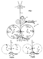
- the present invention is illustrated as applied to a typical signature folder, a portion of which is schematically illustrated in FIG. 1.
- the signature feeds down along a former board and between a pair of rolls 10 and 11 below the former.
- the signature 12 is in the form of a continuous web.
- Below the rolls 10 and 11 is a pinch roll station 13.
- the pinch rolls are adjustable by a hand wheel 14.
- the continuous web signature 12 continues to a folding station 16, at which two counter-rotating cylinders 17 and 18 are located.
- the first cylinder 17 is journaled for anti-clockwise rotation around a pivot axis 21 and the second cylinder 18 is journaled for clockwise rotation about its pivot axis 22.
- first and second cylinders Various signature gripping and cutting mechanisms are carried by the first and second cylinders. These mechanisms are schematically illustrated in FIG. 1.
- tucker blades 23 are mounted on the first cylinder which cooperate with fold jaws 24 on the second cylinder 18 in the manner described in greater detail below.
- impaling pins 26 on the first cylinder 17 cooperate with a female cutting iron or cutting rubber 27 on the second cylinder 18 to separate the preceding signature passing between the cylinders 17 and 18 from the continuous web 12 and to grip the leading edge of the web so that it will be carried by the impaling pins 26 along the surface of the first cylinder 17.
- the second cylinder 18 is illustrated as provided with tucker blades 28 which cooperate with folding jaws on a subsequent or third cylinder (not illustrated).
- a vacuum roller assembly 32 mounted below the throat 31 through which the signatures pass into the folding station 16 is a vacuum roller assembly 32.
- Such assembly 32 functions to prevent the tail whipping in accordance with the present invention and smoothly feeds portions of the signature from the periphery of the first cylinder 17 onto the second cylinder 18.
- the vacuum roller assembly 32 includes a vacuum roll 33 and a guide system, including a first guide portion 34 extending along the periphery of the first cylinder 17 and a second guide portion 36 extending along the periphery of the second cylinder 18.
- the vacuum roll 33 is structured, as discussed below, so that it produces a vacuum zone indicated within the bracket 37 along the upper surface of the roll between the two guide portions 34 and 36. Also, this vacuum tends to produce zones of low pressure along the two guide portions 34 and 36.
- the leading edge of the signature web 12 is pressed onto the impaling pins 26 of the cylinder 17 when the condition of FIG. 2a is reached.
- the leading edge of the web 12 is carried by the impaling pins 26 along the periphery of the first cylinder 17 to a position illustrated in FIG. 2b which is displaced from the position of FIG. 2a by 90 degrees of rotation of the two cylinders 17 and 18.
- one-half of the signature is positioned along the periphery of the first cylinder 17 and the tucker blades 23 on the first cylinder 17 are in alignment with the associated first fold jaw 24 on the second cylinder 18.
- FIG. 2c illustrates the position in which the first fold jaws 24 on the second cylinder 18 are commencing to carry the remaining portion of the signature along the periphery of the second cylinder 18.
- the first portion or leading half of the signature 41 has moved along the periphery of the cylinder 17 to about its maximum extent.
- the impaling pins 26, which grip the forward edge of the signature are withdrawn, releasing the signature from the first cylinder so that it can move from the first cylinder 17 onto the periphery of the second cylinder 18, as progressively illustrated in FIGS. 2d, 2e, and 2f.
- an associated subsequent impaling pin cutter iron 27 operates to cut a completed signature 42 from the signature web 12 and the leading edge of the web 12 is carried by the impaling pins 26 along the periphery of the first cylinder 17 to repeat the cycle of operation.
- the commencement of this operation is illustrated in FIG. 2e.
- the direction of the first half 41 of the signature 42 reverses its direction of movement. Up until such point in the cycle, the first half 41 of the signature has been moving in a direction to the right, as viewed in the drawings. However, immediately thereafter, the direction of movement of the first half 41 of the signature 42 must reverse and move in the direction indicated by the arrow 43 in FIG. 2d. Such reversed direction movement continues through the condition of FIG. 2e and FIG. 2f until the entire signature 42 extends along the periphery of the second cylinder 18, as illustrated in FIG. 2f.
- the tail whipping of the prior art is eliminated by the present invention because a vacuum exists between the roll 33 and such first half of signature 41. This tends to remove the air from one side of the signature half, which would otherwise suspend such signature half and create a condition which allows the tail 44 to whip upon direction reversal. Further, geometry tends to produce a condition in which the signature half moves into engagement with the guide 34 and into engagement with the roll 33, as illustrated in FIG. 2d. Therefore, not only is the whipping of the signature prevented, but a light drag is provided against the signature half 41 which causes it to move smoothly from the position of FIG. 2d to the position of FIG. 2f, when it is located against the periphery of the second cylinder 18.
- the roller 33 itself is freely rotating so that excessive drag is not created on the signature half as the signature half moves along the surface of the roller.
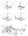
- the structure of the vacuum roller assembly 23 is best illustrated in FIGS. 3 and 4.
- the assembly 32 is supported by spaced frame members 51 mounted on portions of the folder frame (not illustrated).
- Such frame members 51 provide a clamping structure 52 which clamps onto a vacuum tube 53 substantially adjacent to each end thereof.
- Such clamping structure also provides the mounting for a guide support 54 adjacent to each end of the tube.
- the guide supports are pieces of strap material shaped to provide a first curved portion 56 which extends along the first guide portion 34 and a second support portion 57 which extends along the underside of the second guide portion 36.
- Longitudinally extending bars 58 and 59 extend between the supports 54 so that additional support members 61 may be provided at intervals along the length of the guide portion 34.
- a bar 62 extends between the supports 54 so that intermediate supports 63 are provided along the length of the guide portion 36.
- the two guide portions 34 and 36 are formed of plastic or other sheet material and are provided with a smooth finish.
- the trailing edge 64 of the guide portion 34 is preferably beveled, as illustrated in FIG. 3, so that the signature moves smoothly from such guide surface to the roll 33.
- the leading edge 66 of the guide portion 36 is beveled so that the signature can move smoothly from the roll 33 onto the surface of the guide portion 36.
- Vacuum fittings 71 are provided at each end of the tube 53 and are connected to a source of vacuum (not illustrated).
- the roll 33 is a tubular member (as best illustrated in FIG. 4) which is mounted on end plates 72, which are in turn journaled by bearings 70 on the tube 53. Therefore, the roll 33 is freely rotatable about the the tube 53. A section along the top of the tube within the roll is removed so that the vacuum therein can draw air from the interior of the roll 34 into the tube for evacuation through the tube ends to the vacuum source. Similarly, specially configured ports 74 as described below are provided at intervals along the length of the roll 33 so that air can be drawn into the interior of the roll by the vacuum existing therein.
- a generally semi-cylindrical deflector 76 is mounted on the tube 53 within the roll 33 so as to concentrate the effect of the vacuum along the upper side of the roll 33 along which the signature half 41 moves during the operation of the folder.
- each port 74 is designed so as to reduce flow and concentrate the vacuum at the surface of the roll 33.
- each port 74 has a cylindrical passage portion 80 communicating with the interior of the roll 33.
- the passage portion 80 communicates with a converging passage portion 81 which intersects the outer surface of the roll 33. It has been found that the angle shown in FIG. 5 between the converging walls of the portion 80 should be approximately 60°, that the diameter of the portion 80 of the port 74 should be approximately 1/8", and the diameter of the portion 81 at the roll surface should be 3/8". Obviously, other dimensions of the port 74 could probably be developed but the above noted dimensions have been found to be particularly advantageous.
- portion 81 in plan view would be an oval configuration on the surface of the roll in view of the fact that portion 81 is formed by engaging the roll with a tapered type drill which forms a circular opening but, in view of the curvature of the roll in plan view of the opening 81 would be oval.
- FIG. 6 A further embodiment of the present invention is illustrated in FIG. 6.
- the invention is shown as applied to a folder 100.
- the folder 100 has a pair of folding cylinders 101, 102. Web material is advanced into the nip between the rolls 101 and 102.
- the cylinder 102 has cutting knives 103 located at diametrically spaced points on the cylinder. The cutting knives 103 cooperate with the roll 101 to cut the web material as it is advanced through the nip.
- the cylinder 102 also has a pair of tucking blades 104. The tucking blades 104 cooperate with jaws 106 on the cylinder 101 and tuck the material into the jaws 106 to fold it.
- the cylinder 101 cooperates with an upper delivery cylinder 112 and a lower delivery cylinder 114.
- the cylinder 101 will deliver signatures to either the upper or lower delivery cylinder as is known.
- the folder 100 includes a cylinder 115 which has jaws 116 thereon.
- the cylinder 115 is used in the situation where a second fold of the signature is desired. If the second fold of the signature is desired, tucker blades 120 are positioned on cylinder 101. The tucker blades 120 engage the signature which has already been folded the first time by the cylinders 101 and 102 and tuck that folded signature into one of the jaws 116 on the cylinder 115. This folds the signature a second time, and transfers the signature to the cylinder 115. The signature is then released from the cylinder 115 to a suitable delivery system (not shown).
- the folder 100 has a vacuum guide system 125 similar to that described in the embodiment of FIG. 1 in the location at the nip between the cylinders 101, 102.
- a vacuum guide 126 is provided in the nip between the cylinders 101, 115.
- the vacuum guide 126 has a vacuum applied internally thereof and has a perforated housing.
- the vacuum guide applies vacuum in the nip area between the cylinders 101, 115. This vacuum attracts the folded signature to the guide 126 and controls the movement of the signature onto the cylinder 115 when the signature is reversed in its direction of rotation due to being folded into the jaws 116 by the tucker blades 120.
- FIG. 6 utilizes vacuum to control a signature which is being folded between the cylinders 101, 115.
Landscapes
- Folding Of Thin Sheet-Like Materials, Special Discharging Devices, And Others (AREA)
Description
- This invention relates generally to signature folders for publication presses and the like, and more particularly to a novel and improved system for preventing tail whipping when the direction of movement of a portion of signature is reversed.
- Signature folders for publication presses and the like are well known, see e.g. US-A-2 659 437. Such folders often provide a pair of counter-rotating cylinders which define a nip or throat through which the signatures pass during the folding operation. Gripping means are provided which grip the signature at spaced locations and cause the intermediate signature portion between such locations to move first along the periphery of one cylinder and then reverse directions and move along the periphery of the other cylinder.
- This reversal in direction of movement often creates problems of tail whipping that can tear or otherwise damage the signatures. Such problem tends to be aggravated as the speed of operation of the folder is increased. Guides have sometimes been provided in an attempt to reduce such tail whipping, but they are only partially effective, and the problem continues to exist particularly in folders which operate at high speeds.
- With the present invention, the problem of tail whipping in signature folders is virtually eliminated, even when the folder operates at high speeds.
- In accordance with the present invention, vacuum means is provided to create a vacuum between guide means and a signature portion as defined in
claim 1. Such vacuum removes the air cushion along one side of the signature tail and the pressure along the other side of the signature tail tends to press the signature tail over against a perforated vacuum roll. This prevents the initial whipping action. - As the signature moves in the reverse direction, it is carried over the freely rotating vacuum roll which provides sufficient drag to ensure that the signature tail remains smooth, and subsequently smoothly feeds onto the cylinder periphery.
- In the illustrated embodiment of this invention, the vacuum roll is journaled within the zone between the two cylinders and below the throat. Such roll is freely journaled on bearings for rotation about an axis parallel to the axis of rotation of the two cylinders. Also provided are guides which extend from the roll in substantially a tangential manner with respect to the roll and in closely spaced relationship to the peripheries of the two cylinders. Because the area between the guides and the rollers is relatively closed, the vacuum supplied to the roll tends to evacuate the air cushion between the cylinders and the roll. As the signature is positioned between each of the cylinders and the adjacent guides, the vacuum tends to pull the signature over against the guides, reducing the tendency for the signature to whip during direction reversals.
- The roll is not driven in the illustrated embodiment, but is rotated by its contact with the signature as the signature is pulled along the surface of the roll. Such roll and guides provide a light friction-induced drag on the signature, which tends to keep the signature smooth as it feeds across the roll onto the subsequent cylinder.
- These and other aspects of this invention are illustrated in the accompanying drawings, and are more fully described in the following specification.
- FIG. 1 is a schematic side elevation of a signature folder incorporating a vacuum roll system in accordance with the present invention;
- FIG. 2a schematically illustrates the system when the leading edge of a signature enters the throat between the cylinders and is gripped by impaling pins on one cylinder;
- FIG. 2b is a view similar to FIG. 2a but illustrates the condition which exists after the first half of the signature has been moved through the throat and onto the periphery of the first or forward cylinder. In such position, a central portion of the signature is tucked into fold jaws on the second cylinder by a tucker blade carried by the first cylinder;
- FIG. 2c is a view similar to FIGS. 2a and 2b, but illustrates the folder in a position in which the portion of the signature extending along the periphery of the first cylinder reverses in direction and commences to move in the opposite direction so that it can be positioned along the periphery of the second cylinder;
- FIG. 2d is similar to the preceding three figures, but illustrates the system at a position in which the signature engages the vacuum roll and commences feeding onto the periphery of the cylinder;
- FIG. 2e is a view similar to the preceding schematic figures 2a through 2d, but illustrates the condition when the signature is substantially completely wrapped along the periphery of the second cylinder;
- FIG. 2f is similar to FIGS. 2a through 2e, but illustrates the condition when the signature is leaving the vacuum system;
- FIG. 3 is an enlarged, fragmentary, side elevation of the vacuum system;
- FIG. 4 is a plan view of the vacuum system;
- FIG. 5 is a cross sectional view of a vacuum opening in the periphery of the vacuum roll in the embodiment of FIG. 1; and
- FIG. 6 is a schematic view of a different folder embodying the present invention.
- The present invention is illustrated as applied to a typical signature folder, a portion of which is schematically illustrated in FIG. 1. In such folder, the signature feeds down along a former board and between a pair of
rolls 10 and 11 below the former. In such portion of the folder, thesignature 12 is in the form of a continuous web. Below therolls 10 and 11 is a pinch roll station 13. The pinch rolls are adjustable by a hand wheel 14. From the pinch roll station, thecontinuous web signature 12 continues to afolding station 16, at which twocounter-rotating cylinders first cylinder 17 is journaled for anti-clockwise rotation around apivot axis 21 and thesecond cylinder 18 is journaled for clockwise rotation about its pivot axis 22. - Various signature gripping and cutting mechanisms are carried by the first and second cylinders. These mechanisms are schematically illustrated in FIG. 1. For example,
tucker blades 23 are mounted on the first cylinder which cooperate withfold jaws 24 on thesecond cylinder 18 in the manner described in greater detail below. Similarly, impalingpins 26 on thefirst cylinder 17 cooperate with a female cutting iron or cuttingrubber 27 on thesecond cylinder 18 to separate the preceding signature passing between thecylinders continuous web 12 and to grip the leading edge of the web so that it will be carried by theimpaling pins 26 along the surface of thefirst cylinder 17. Thesecond cylinder 18 is illustrated as provided withtucker blades 28 which cooperate with folding jaws on a subsequent or third cylinder (not illustrated). - The structure described thus far is conventional structure, and forms no part of the present invention except as it cooperates with the vacuum mechanism to reduce or eliminate any tail whipping and the like. It has not been illustrated or discussed in greater detail because it is well known to those skilled in the art.
- Mounted below the
throat 31 through which the signatures pass into thefolding station 16 is avacuum roller assembly 32.Such assembly 32 functions to prevent the tail whipping in accordance with the present invention and smoothly feeds portions of the signature from the periphery of thefirst cylinder 17 onto thesecond cylinder 18. - The
vacuum roller assembly 32 includes avacuum roll 33 and a guide system, including afirst guide portion 34 extending along the periphery of thefirst cylinder 17 and asecond guide portion 36 extending along the periphery of thesecond cylinder 18. - The particular structure of the illustrated embodiment of the vacuum roll assembly is discussed in greater detail below; however, its general operation and the manner in which it prevents tail whipping and promotes smooth feeding will be discussed first.
- The
vacuum roll 33 is structured, as discussed below, so that it produces a vacuum zone indicated within thebracket 37 along the upper surface of the roll between the twoguide portions guide portions - In operation, the leading edge of the
signature web 12 is pressed onto theimpaling pins 26 of thecylinder 17 when the condition of FIG. 2a is reached. As the two cylinders counter-rotate about theirrespective axes 21 and 22, the leading edge of theweb 12 is carried by theimpaling pins 26 along the periphery of thefirst cylinder 17 to a position illustrated in FIG. 2b which is displaced from the position of FIG. 2a by 90 degrees of rotation of the twocylinders first cylinder 17 and thetucker blades 23 on thefirst cylinder 17 are in alignment with the associatedfirst fold jaw 24 on thesecond cylinder 18. These cooperate to cause thesignature web 12 to be gripped by thefirst fold jaws 24 so that the remaining portion of the signature will be carried along the periphery of thesecond cylinder 18 and not thefirst cylinder 17. - This is best illustrated in FIG. 2c, which illustrates the position in which the
first fold jaws 24 on thesecond cylinder 18 are commencing to carry the remaining portion of the signature along the periphery of thesecond cylinder 18. At about this position, the first portion or leading half of thesignature 41 has moved along the periphery of thecylinder 17 to about its maximum extent. At this time, the impaling pins 26, which grip the forward edge of the signature, are withdrawn, releasing the signature from the first cylinder so that it can move from thefirst cylinder 17 onto the periphery of thesecond cylinder 18, as progressively illustrated in FIGS. 2d, 2e, and 2f. - When the two
cylinders pin cutter iron 27 operates to cut a completedsignature 42 from thesignature web 12 and the leading edge of theweb 12 is carried by the impaling pins 26 along the periphery of thefirst cylinder 17 to repeat the cycle of operation. The commencement of this operation is illustrated in FIG. 2e. - At about the point in the cycle of operation illustrated in FIG. 2c, the direction of the
first half 41 of thesignature 42 reverses its direction of movement. Up until such point in the cycle, thefirst half 41 of the signature has been moving in a direction to the right, as viewed in the drawings. However, immediately thereafter, the direction of movement of thefirst half 41 of thesignature 42 must reverse and move in the direction indicated by the arrow 43 in FIG. 2d. Such reversed direction movement continues through the condition of FIG. 2e and FIG. 2f until theentire signature 42 extends along the periphery of thesecond cylinder 18, as illustrated in FIG. 2f. - The operation and movement of the signature thus far described are substantially conventional, and exist in prior art machines. However, in such prior art machines, the tail 44 of the
signature half 41 tends to snap or whip in a violent manner much the same as when a towel is snapped. This often produces tears or damage in the signature half. Also, the violence of this whipping action prevents the signature half from smoothly feeding onto thesecond cylinder 18. - The tail whipping of the prior art, however, is eliminated by the present invention because a vacuum exists between the
roll 33 and such first half ofsignature 41. This tends to remove the air from one side of the signature half, which would otherwise suspend such signature half and create a condition which allows the tail 44 to whip upon direction reversal. Further, geometry tends to produce a condition in which the signature half moves into engagement with theguide 34 and into engagement with theroll 33, as illustrated in FIG. 2d. Therefore, not only is the whipping of the signature prevented, but a light drag is provided against thesignature half 41 which causes it to move smoothly from the position of FIG. 2d to the position of FIG. 2f, when it is located against the periphery of thesecond cylinder 18. - The
roller 33 itself is freely rotating so that excessive drag is not created on the signature half as the signature half moves along the surface of the roller. - The structure of the
vacuum roller assembly 23 is best illustrated in FIGS. 3 and 4. Theassembly 32 is supported by spacedframe members 51 mounted on portions of the folder frame (not illustrated).Such frame members 51 provide a clampingstructure 52 which clamps onto avacuum tube 53 substantially adjacent to each end thereof. Such clamping structure also provides the mounting for aguide support 54 adjacent to each end of the tube. The guide supports are pieces of strap material shaped to provide a firstcurved portion 56 which extends along thefirst guide portion 34 and asecond support portion 57 which extends along the underside of thesecond guide portion 36. -
Longitudinally extending bars supports 54 so thatadditional support members 61 may be provided at intervals along the length of theguide portion 34. Similarly, abar 62 extends between thesupports 54 so thatintermediate supports 63 are provided along the length of theguide portion 36. Preferably, the twoguide portions guide portion 34 is preferably beveled, as illustrated in FIG. 3, so that the signature moves smoothly from such guide surface to theroll 33. Similarly, the leading edge 66 of theguide portion 36 is beveled so that the signature can move smoothly from theroll 33 onto the surface of theguide portion 36. -
Vacuum fittings 71 are provided at each end of thetube 53 and are connected to a source of vacuum (not illustrated). Theroll 33 is a tubular member (as best illustrated in FIG. 4) which is mounted onend plates 72, which are in turn journaled bybearings 70 on thetube 53. Therefore, theroll 33 is freely rotatable about the thetube 53. A section along the top of the tube within the roll is removed so that the vacuum therein can draw air from the interior of theroll 34 into the tube for evacuation through the tube ends to the vacuum source. Similarly, specially configuredports 74 as described below are provided at intervals along the length of theroll 33 so that air can be drawn into the interior of the roll by the vacuum existing therein. A generallysemi-cylindrical deflector 76 is mounted on thetube 53 within theroll 33 so as to concentrate the effect of the vacuum along the upper side of theroll 33 along which thesignature half 41 moves during the operation of the folder. - One of the
ports 74 is shown in FIG. 5. Eachport 74 is designed so as to reduce flow and concentrate the vacuum at the surface of theroll 33. Specifically, eachport 74 has acylindrical passage portion 80 communicating with the interior of theroll 33. Thepassage portion 80 communicates with a convergingpassage portion 81 which intersects the outer surface of theroll 33. It has been found that the angle shown in FIG. 5 between the converging walls of theportion 80 should be approximately 60°, that the diameter of theportion 80 of theport 74 should be approximately 1/8", and the diameter of theportion 81 at the roll surface should be 3/8". Obviously, other dimensions of theport 74 could probably be developed but the above noted dimensions have been found to be particularly advantageous. Further, it should be clear that theportion 81 in plan view would be an oval configuration on the surface of the roll in view of the fact thatportion 81 is formed by engaging the roll with a tapered type drill which forms a circular opening but, in view of the curvature of the roll in plan view of theopening 81 would be oval. - A further embodiment of the present invention is illustrated in FIG. 6. In FIG. 6 the invention is shown as applied to a
folder 100. Thefolder 100 has a pair offolding cylinders rolls cylinder 102 has cuttingknives 103 located at diametrically spaced points on the cylinder. The cuttingknives 103 cooperate with theroll 101 to cut the web material as it is advanced through the nip. Thecylinder 102 also has a pair of tuckingblades 104. Thetucking blades 104 cooperate withjaws 106 on thecylinder 101 and tuck the material into thejaws 106 to fold it. Thecylinder 101 cooperates with anupper delivery cylinder 112 and alower delivery cylinder 114. Thecylinder 101 will deliver signatures to either the upper or lower delivery cylinder as is known. Also, thefolder 100 includes acylinder 115 which hasjaws 116 thereon. Thecylinder 115 is used in the situation where a second fold of the signature is desired. If the second fold of the signature is desired,tucker blades 120 are positioned oncylinder 101. Thetucker blades 120 engage the signature which has already been folded the first time by thecylinders jaws 116 on thecylinder 115. This folds the signature a second time, and transfers the signature to thecylinder 115. The signature is then released from thecylinder 115 to a suitable delivery system (not shown). - The
folder 100 has avacuum guide system 125 similar to that described in the embodiment of FIG. 1 in the location at the nip between thecylinders vacuum guide 126 is provided in the nip between thecylinders vacuum guide 126 has a vacuum applied internally thereof and has a perforated housing. The vacuum guide applies vacuum in the nip area between thecylinders guide 126 and controls the movement of the signature onto thecylinder 115 when the signature is reversed in its direction of rotation due to being folded into thejaws 116 by thetucker blades 120. Thus, it should be apparent that the embodiment of FIG. 6 utilizes vacuum to control a signature which is being folded between thecylinders - With the vacuum assembly illustrated, it is not necessary to provide any separate power drive for the roller and the only supply connection required is the vacuum connection to the fitting 71. Therefore, a very simple mechanism is provided to eliminate the tail whipping which has existed in the prior art and to provide a light drag or friction on the signature half as it feeds to the
second cylinder 18 in a smooth, undamaging manner. - With the present invention, higher operating speeds can be achieved without tail whipping problems and an improved signature folding operation is provided.
- Although the preferred embodiment of this invention has been shown and described, it should be understood that various modifications and rearrangements of the parts may be resorted to without departing from the scope of the invention as disclosed and claimed herein.
Claims (4)
- A signature folder (16, 100) comprising drive means (17, 18, 101, 102) to move at least a portion of a signature (41) first in one direction and then in a reverse direction, guide means (32, 125) adjacent to said portion (41) when it reverses direction, characterized by vacuum means operable to create a vacuum between said guide means (32, 125) and signature portion (41) operating to move said portion (41) toward said guide means (32, 125) to prevent tail whipping when said portion reverses in direction, said guide means (32, 125) including a rotatable roll (33) connected to a vacuum source, said roll (33) being freely rotated by engagement with said signature portion (41).
- A signature folder (16, 100) as set forth in claim 1, further characterized by said guide means (32, 125) including a smooth stationary guide portion (34) adjacent to said roll (33).
- A signature folder (16, 100) as set forth in claim 1, further characterized by said roll (33) being journalled on a vacuum tube (53) which connects to the interior of said roll (33) and provides a vacuum therein, and smooth guide means (34, 36) being provided on each side of said roll (33) to guide said signature portion (41) into and out of engagement with said roll (33).
- A signature folder (16, 100) as set forth in claim 3, wherein a shield (76) is provided to concentrate vacuum along one side of said roll (33), further characterized by said shield (76) being located inside of said roll (33) and supported on said tube (53).
Applications Claiming Priority (2)
| Application Number | Priority Date | Filing Date | Title |
|---|---|---|---|
| US789503 | 1985-10-21 | ||
| US06/789,503 US4666139A (en) | 1985-10-21 | 1985-10-21 | Vacuum system for combination fold-off control |
Publications (3)
| Publication Number | Publication Date |
|---|---|
| EP0220644A2 EP0220644A2 (en) | 1987-05-06 |
| EP0220644A3 EP0220644A3 (en) | 1988-12-07 |
| EP0220644B1 true EP0220644B1 (en) | 1991-06-12 |
Family
ID=25147828
Family Applications (1)
| Application Number | Title | Priority Date | Filing Date |
|---|---|---|---|
| EP86114508A Expired EP0220644B1 (en) | 1985-10-21 | 1986-10-20 | Vacuum system for combination fold-off control |
Country Status (5)
| Country | Link |
|---|---|
| US (1) | US4666139A (en) |
| EP (1) | EP0220644B1 (en) |
| JP (1) | JPS62161680A (en) |
| CA (1) | CA1281044C (en) |
| DE (1) | DE3679769D1 (en) |
Cited By (2)
| Publication number | Priority date | Publication date | Assignee | Title |
|---|---|---|---|---|
| DE4217814A1 (en) * | 1992-05-29 | 1993-12-02 | Heidelberger Druckmasch Ag | Device to support the controlled transport of copies in the folder of rotary printing presses |
| DE4234307A1 (en) * | 1992-10-12 | 1994-04-14 | Heidelberger Druckmasch Ag | Device for trouble-free product conveyance in folders |
Families Citing this family (17)
| Publication number | Priority date | Publication date | Assignee | Title |
|---|---|---|---|---|
| DE3601660A1 (en) * | 1986-01-21 | 1987-07-23 | Eltex Elektrostatik Gmbh | METHOD AND DEVICE FOR FOLDING SHEETS CUT FROM A CONTINUOUS MATERIAL |
| DE3705195A1 (en) * | 1987-02-19 | 1988-09-01 | Frankenthal Ag Albert | CONTROL DEVICE |
| DE8809285U1 (en) * | 1988-07-20 | 1988-09-01 | Heidelberger Druckmaschinen Ag, 6900 Heidelberg | Device for guiding copy sections in the folding apparatus of rotary printing machines |
| US5226871A (en) * | 1991-07-03 | 1993-07-13 | Rockwell International Corporation | Folder with gradual guide assembly and method |
| DE59303826D1 (en) * | 1992-05-29 | 1996-10-24 | Heidelberger Druckmasch Ag | Device to support the controlled transport of copies in the folder of rotary printing presses |
| DE4342037C1 (en) * | 1993-12-09 | 1995-03-02 | Frankenthal Ag Albert | Method and device for transversely folding signatures |
| DE19708213A1 (en) * | 1996-04-09 | 1997-10-30 | Heidelberger Druckmasch Ag | Method and device for product guidance in a fold formation area of a folding apparatus |
| US6746389B2 (en) * | 1997-10-31 | 2004-06-08 | Cmd Corporation | Method and apparatus for folding or separating bags |
| DE19845214A1 (en) * | 1998-10-01 | 2000-04-06 | Heidelberger Druckmasch Ag | Printing machine cylinders, in particular impression cylinders for a sheet-fed rotary machine |
| DE29916083U1 (en) * | 1999-09-14 | 1999-11-18 | MAN Roland Druckmaschinen AG, 63075 Offenbach | Sheet guiding device with a guide surface in a printing press |
| US6551227B1 (en) * | 1999-12-08 | 2003-04-22 | Heidelberger Druckmaschinen Ag | Device for seizing of flat material on a transporting surface |
| DE10312821B4 (en) * | 2003-03-22 | 2005-12-01 | Koenig & Bauer Ag | Device for the transverse folding of sheets of flat material |
| US8617040B2 (en) * | 2010-12-17 | 2013-12-31 | Kimberly-Clark Worldwide, Inc. | Folding apparatus and method of folding a product |
| ITFI20110048A1 (en) * | 2011-03-30 | 2012-10-01 | Rent Srl | BENDING GROUP FOR PRODUCTS IN THE SHEET |
| US9371209B2 (en) | 2012-05-01 | 2016-06-21 | C.G. Bretting Manufacturing Co., Inc. | Single path single web single-fold interfolder and methods |
| US10449746B2 (en) | 2016-06-27 | 2019-10-22 | C. G. Bretting Manufacturing Co., Inc. | Web processing system with multiple folding arrangements fed by a single web handling arrangement |
| CN112693178B (en) * | 2020-12-21 | 2022-05-06 | 浙江大学 | An origami wheel module with combined bearing device |
Family Cites Families (9)
| Publication number | Priority date | Publication date | Assignee | Title |
|---|---|---|---|---|
| US1974149A (en) * | 1932-06-22 | 1934-09-18 | Paper Converting Machine Co | Sheet-folding machine |
| US2659437A (en) * | 1947-03-04 | 1953-11-17 | Huck Co | Cutting and gripping mechanism for printing machines |
| US2969980A (en) * | 1958-09-08 | 1961-01-31 | Miehle Goss Dexter Inc | Vacuum slow down device for sheet delivery mechanism |
| US3506255A (en) * | 1967-06-07 | 1970-04-14 | Leipzig Veb Druckmasch Werke | Apparatus for the manufacture of a second cross-fold on folding devices of rotary printing machines |
| CH485580A (en) * | 1968-04-19 | 1970-02-15 | Hepp Rudolf | Method for spreading individual sheets or sheet units combined from several sheets and device for carrying out the method |
| US3870292A (en) * | 1973-03-16 | 1975-03-11 | Paper Converting Machine Co | Method and apparatus for transverse folding of webs |
| US4082259A (en) * | 1976-12-08 | 1978-04-04 | Harris Corporation | Cylinder folder |
| US4494949A (en) * | 1983-01-10 | 1985-01-22 | The Lehigh Press, Inc. | Sheet folding apparatus and method |
| US4521209A (en) * | 1983-04-22 | 1985-06-04 | Paper Converting Machine Company | Apparatus and method for transverse folding of webs |
-
1985
- 1985-10-21 US US06/789,503 patent/US4666139A/en not_active Expired - Fee Related
-
1986
- 1986-10-20 EP EP86114508A patent/EP0220644B1/en not_active Expired
- 1986-10-20 DE DE8686114508T patent/DE3679769D1/en not_active Expired - Lifetime
- 1986-10-20 CA CA000520841A patent/CA1281044C/en not_active Expired - Lifetime
- 1986-10-21 JP JP61250629A patent/JPS62161680A/en active Pending
Cited By (4)
| Publication number | Priority date | Publication date | Assignee | Title |
|---|---|---|---|---|
| DE4217814A1 (en) * | 1992-05-29 | 1993-12-02 | Heidelberger Druckmasch Ag | Device to support the controlled transport of copies in the folder of rotary printing presses |
| DE4314239A1 (en) * | 1992-05-29 | 1994-11-03 | Heidelberger Druckmasch Ag | Apparatus for supporting the controlled copy transport in the folding apparatus of rotary printing machines |
| DE4314239B4 (en) * | 1992-05-29 | 2004-11-04 | Heidelberger Druckmaschinen Ag | Device for guiding copies in the folder of rotary printing machines |
| DE4234307A1 (en) * | 1992-10-12 | 1994-04-14 | Heidelberger Druckmasch Ag | Device for trouble-free product conveyance in folders |
Also Published As
| Publication number | Publication date |
|---|---|
| DE3679769D1 (en) | 1991-07-18 |
| EP0220644A2 (en) | 1987-05-06 |
| US4666139A (en) | 1987-05-19 |
| CA1281044C (en) | 1991-03-05 |
| JPS62161680A (en) | 1987-07-17 |
| EP0220644A3 (en) | 1988-12-07 |
Similar Documents
| Publication | Publication Date | Title |
|---|---|---|
| US4666139A (en) | Vacuum system for combination fold-off control | |
| US4254947A (en) | Sheet overlap device | |
| US4828195A (en) | Surface winder and method | |
| US4909452A (en) | Surface winder and method | |
| US4717375A (en) | Apparatus for folding a flexible article | |
| US4114520A (en) | Apparatus for making bags from a continuously fed thermoplastic tubular web of film | |
| US6383124B1 (en) | High speed paper folding machine | |
| EP2284001A1 (en) | High speed interfolder | |
| EP0007443B1 (en) | Bag folding machine | |
| EP1520822B1 (en) | Method of and assembly for lapping consecutive sheets of web material | |
| US5484379A (en) | Folder assemby for printing press | |
| US4036487A (en) | Sheet folding apparatus | |
| EP1520818B1 (en) | Assembly for and method of adjusting the phasing of folding rolls in an interfolding machine | |
| US7036413B2 (en) | Device for the transverse cutting of at least one web in a folding apparatus | |
| JPH07206260A (en) | Torso | |
| US6635005B1 (en) | Copy-guiding device having a variable geometry | |
| US3561332A (en) | Bag making machine | |
| JPH0853250A (en) | Paper cutting device | |
| US6126586A (en) | Device for improving folding accuracy in a folder | |
| US4915043A (en) | Device for folding an edge of a fabric for making a hem | |
| US3613288A (en) | Bag making machine | |
| JP2550776Y2 (en) | Rotary printing press folding machine | |
| JP3761852B2 (en) | Folding device | |
| US2128167A (en) | Folder | |
| US6752078B2 (en) | Device for guiding flat or sheet-like copies in folders |
Legal Events
| Date | Code | Title | Description |
|---|---|---|---|
| PUAI | Public reference made under article 153(3) epc to a published international application that has entered the european phase |
Free format text: ORIGINAL CODE: 0009012 |
|
| 17P | Request for examination filed |
Effective date: 19861113 |
|
| AK | Designated contracting states |
Kind code of ref document: A2 Designated state(s): DE FR GB |
|
| PUAL | Search report despatched |
Free format text: ORIGINAL CODE: 0009013 |
|
| AK | Designated contracting states |
Kind code of ref document: A3 Designated state(s): DE FR GB |
|
| 17Q | First examination report despatched |
Effective date: 19900528 |
|
| GRAA | (expected) grant |
Free format text: ORIGINAL CODE: 0009210 |
|
| AK | Designated contracting states |
Kind code of ref document: B1 Designated state(s): DE FR GB |
|
| REF | Corresponds to: |
Ref document number: 3679769 Country of ref document: DE Date of ref document: 19910718 |
|
| ET | Fr: translation filed | ||
| PLBE | No opposition filed within time limit |
Free format text: ORIGINAL CODE: 0009261 |
|
| STAA | Information on the status of an ep patent application or granted ep patent |
Free format text: STATUS: NO OPPOSITION FILED WITHIN TIME LIMIT |
|
| 26N | No opposition filed | ||
| PGFP | Annual fee paid to national office [announced via postgrant information from national office to epo] |
Ref country code: GB Payment date: 19950919 Year of fee payment: 10 |
|
| PGFP | Annual fee paid to national office [announced via postgrant information from national office to epo] |
Ref country code: FR Payment date: 19951009 Year of fee payment: 10 |
|
| PGFP | Annual fee paid to national office [announced via postgrant information from national office to epo] |
Ref country code: DE Payment date: 19951121 Year of fee payment: 10 |
|
| PG25 | Lapsed in a contracting state [announced via postgrant information from national office to epo] |
Ref country code: GB Effective date: 19961020 |
|
| GBPC | Gb: european patent ceased through non-payment of renewal fee |
Effective date: 19961020 |
|
| PG25 | Lapsed in a contracting state [announced via postgrant information from national office to epo] |
Ref country code: FR Effective date: 19970630 |
|
| PG25 | Lapsed in a contracting state [announced via postgrant information from national office to epo] |
Ref country code: DE Effective date: 19970701 |
|
| REG | Reference to a national code |
Ref country code: FR Ref legal event code: ST |