EP0220633B1 - Asymmetric arc chamber for a discharge lamp - Google Patents
Asymmetric arc chamber for a discharge lamp Download PDFInfo
- Publication number
- EP0220633B1 EP0220633B1 EP19860114439 EP86114439A EP0220633B1 EP 0220633 B1 EP0220633 B1 EP 0220633B1 EP 19860114439 EP19860114439 EP 19860114439 EP 86114439 A EP86114439 A EP 86114439A EP 0220633 B1 EP0220633 B1 EP 0220633B1
- Authority
- EP
- European Patent Office
- Prior art keywords
- arc tube
- arc
- section
- metal halide
- tube
- Prior art date
- Legal status (The legal status is an assumption and is not a legal conclusion. Google has not performed a legal analysis and makes no representation as to the accuracy of the status listed.)
- Expired - Fee Related
Links
Images
Classifications
-
- H—ELECTRICITY
- H01—ELECTRIC ELEMENTS
- H01J—ELECTRIC DISCHARGE TUBES OR DISCHARGE LAMPS
- H01J61/00—Gas-discharge or vapour-discharge lamps
- H01J61/82—Lamps with high-pressure unconstricted discharge having a cold pressure > 400 Torr
- H01J61/827—Metal halide arc lamps
-
- H—ELECTRICITY
- H01—ELECTRIC ELEMENTS
- H01J—ELECTRIC DISCHARGE TUBES OR DISCHARGE LAMPS
- H01J61/00—Gas-discharge or vapour-discharge lamps
- H01J61/02—Details
- H01J61/30—Vessels; Containers
Definitions
- the present invention relates to metal vapor discharge lamps, and, more particularly, to an asymmetrically shaped arc chamber for such lamps.
- EP-A-0 173 347 discloses an arc tube for a metal vapor discharge lamp having the same shape as the arc tube described in claim 1, the envelope of said tube having one end larger than the other end, first and second electrodes are disposed in both said ends, and a discharge-supporting medium is contained within said envelope, said medium comprising mercury, inert gas and metal halide such as NaJ and ScJ3.
- Ca-A-508 525 describes an egg-shaped arc tube containing a discharge-supporting medium consisting of mercury, cadmium and/or zinc.
- DE-A-29 30 328 describes a miniature arc tube having a volume of less than 1 ml (for example, 0,11 ml) containing mercury and a mixture of metal halides (NaI, ScI3 and ThI4) the amount of which is for example 1,98 mg/cm2 of internal arc tube surface and less than the amount of Hg.
- Lamp color and lumen performance are improved by high vapor pressure of the halides in the arc which is dependent upon the wall temperature of the arc chamber.
- Wall temperatures of the arc chamber in vertical operation are determined by the input power to the arc chamber, the geometry and design of the electrodes and the arc chamber shape. Wall temperatures are also affected by convection speeds and flow patterns, arc radiation efficiency and the amount of halide wall coverage. Of particular significance with respect to wall temperatures are convective flow patterns which bring the arc close to the chamber wall apparently due to flow instabilities in the arc fluid.
- the amount of halide condensate wall coverage affects wall temperature, because evaporation of the halide from the arc chamber wall has a cooling effect, and evaporation of halide condensate from the arc chamber wall causes the wall temperature to be lower than it would be if the wall were clear.
- the presence of metal halide condensate also affects arc tube wall temperature distribution, since the presence of extensive halide condensate causes arc asymmetries which create local bare spots running at somewhat higher temperatures than the portions of the arc tube wall coated with condensate.
- An object of the present invention is to provide a shaped arc chamber for metal vapor discharge lamps in which the electrodes are positioned and the arc chamber walls are shaped so that distribution of metal halide condensate upon the arc chamber wall is promoted.
- a more particular object of the present invention is to provide an asymmetrical arc chamber having a surface area at one end of the arc tube greater than the surface area at the other end.
- the present invention provides an arc tube as defined in claim 1.
- the degree of electrode insertion of each of the electrodes into the respective ends of arc chamber and the dimensions of the arc tube are selected in combination with the amount of fill material so that a sufficient amount of vapor is maintained within the arc tube during operation.
- the present invention further includes a high intensity discharge lamp having a vitreous outer envelope for enclosing the arc tube and supporting the arc tube such that the smaller end thereof is located at the bottom during normal lamp operation.
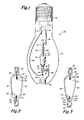
- Fig. 1 is a schematic elevation view illustrating a lamp incorporating the arc chamber construction of the present invention
- Fig. 2 is a schematic partial cross sectional view of one preferred embodiment of the arc chamber of the present invention
- Fig. 3 is a schematic partial cross sectional view of an alternative embodiment of the arc chamber of the present invention.
- a lamp incorporating the present invention is designed to be operated vertically with the base at the top as illustrated schematically in Fig. 1.
- the lamp 10 includes an outer envelope 12 of vitreous material such as glass having a suitable composition for a high intensity discharge lamp and a base 14 having suitable electrical contacts for making electrical connection to an appropriate socket.
- the space within the outer envelope 12 may be evacuated or filled with nitrogen gas to 0.5 bar.
- the end cap 14 surrounds the stem 16 of the lamp through which electrically conductive terminal wires 18 and 20 extend.
- Terminal 18 is connected to support rod 22 to which support member 24 is attached.
- An electrically conductive inlead 26 connected to support member 24 on one end is connected to foil member 28 which is connected to electrode stem 30 of the electrode 32.
- a support lead 34 is connected to terminal 20 and is connected directly to inlead 36 which is connected to the foil member 38 connected to electrode stem 40 of electode 42.
- An anchoring dimple 44 is provided at the bottom end of the outer envelope 12 so that a metallic collar 46 may be disposed thereon to support rod 48 connected by support member 50 to the stem 52 of arc tube 54.
- the stems 52 and 56 of the arc tube are sealed around the ribbon members 28 and 38 to seal the interior of the arc tube.
- the arc tube 54 is shown in more detail in Fig. 2.
- the arc chamber 54 comprises an inner envelope of vitreous material such as thin walled fused silica sealed at the respective ends as described above with the electrodes 32 and 42 projecting into the interior from the respective ends thereof.
- a suitable filling is disposed within the arc chamber 54 and comprises a discharge medium of, for example, a quantity of amalgam of mercury and an excess amount of metal halide dose, for example, about 15 to 25 milligrams of a 0 to 5 molar percent cadmium/amalgam, and 25 to 45 milligrams of a combination of sodium iodide, scandium iodide and thorium iodide in predetermined nominal weight percents of NaI, ScI3, and ThI4, plus an inert fill gas for example argon at a pressure of 10640-15960 Pa (80 to 120 torr).
- the quantity of metal halide dose is selected to be substantially in excess of the amount which is vaporized in operation of the lamp.
- the dose is selected to equal at least 2.0 milligrams of metal halide dose per square centimeter of arc tube interior surface area.
- the tungsten wire electrodes 32 and 42 are wrapped into the form shown in Fig. 2 and project into the interior of the arc chamber by a predetermined distance so that the vaporization of the amalgam and metal halide dose is maintained at the appropriate level during lamp operation.
- the top electrode 32 projects into the interior of the arc tube at a distance different from and generally greater than the distance the bottom electrode 42 projects.
- An infrared reflective coating 66 as shown in Fig. 2 is applied to the exterior surface 68 of the narrow end 60 of the arc tube 54.
- the bottom bowl 60 of the arc tube 54 has a generally hemispherical shape with a certain internal radius and the upper bowl 70 of the arc tube 54 has a hemispherical shape with an internal radius larger than that of bottom bowl 60.
- the middle section 72 of the arc tube is a generally tapered hollow member with one end having a radius matching the bottom bowl radius and the other end having a radius matching the top bowl radius, so that the transition between the middle section and respective generally hemispherical ends of the arc tube is smooth.
- the arc tube 80 has an upper end 82 having a first radius a lower end 84 having a second radius substantially smaller than the first radius and a tapered mid section 86 whose upper end has a radius equal to said first radius and whose bottom end has a radius equal to said second radius.
- Electrode 88 projects into the interior of the arc chamber such that the tip thereof 90 is located at a first distance from the surface of the arc tube at the point 92 where the electrode stem 94 extends into the fused silica of the arc tube.
- the electrode stem 94 is connected to a ribbon contact 96 at the location of a seal at the upper end of the arc tube and is connected to an inlead wire 98 for connection to the contacts of a lamp as shown in Fig. 1.
- the bottom electrode 100 is disposed in the narrower end 84 of the arc tube and positioned such that the tip 102 is located at a second distance less than the first distance from the surface 104 of the interior of the arc tube at the point where the electrode stem 106 projects through the fused silica to make contact with the ribbon contact 108 which is connected to the inlead wire 110.
- An infrared coating 112 is disposed about the outer surface of the narrow end 84 of the arc tube 80.
- the amount of halide dose is selected to equal at least 2.0 milligrams of dose per square centimeter of interior arc tube surface area.
- the present invention is not limited to hemispherical shapes at the respective ends of the arc tube, but includes any generally rounded shape so long as the interior surface of the arc tube is smooth with no discontinuities in the surface.
- either one or both of the ends could be parabolic or ellipsoidal.
- both ends have similar geometric shapes; for example, one end could be hemispherical and the other ellipsoidal.
- the requirement is that one end be from 1.2 to 2.0 times the cross section of the other end and that the two ends be joined by a smoothly tapered middle section.
- the arc tube of the present invention may be installed in a lamp having the base for connection at the bottom, rather than at the top as shown in Fig.
- the arc tube may be installed in an outer envelope designed for horizontal installation in a fixture. Any of these outer envelope configurations can be used with the arc tube of the present invention, so long as the mounting structure for supporting the arc tube within the outer envelope positions the arc tube vertically within manufacturing tolerances with the smaller end of the arc tube at the bottom.
- the end cap is screwed into a suitable power supply system having a suitable ballasting arrangement for operation of the metal vapor discharge lamp.
- the application of a sufficiently high voltage to the electrodes of the arc tube causes ionization of the argon within the lamp to create a glow discharge causing vaporization of at least part of the metal halide contained therein in non-vapor form.
- an arc discharge of the excited metallic halide is established.
- a continuous vaporization and condensation cycle of the metallic halide is maintained as the halide contacts the arc tube wall and condenses, because a fraction of the impinging metal halide molecules fall below the condensation temperature.
- the effect of distributing the condensate along the arc tube surface is to filter the radiation emitted by the arc tube thereby promoting a lower color temperature in accordance with the light absorbing properties of the condensate film.
- the presence of the distributed condensate is also an indicator that the condensate is not trapped in the cooler regions of the arc tube and, therefore, that metal halide vaporization is occurring at higher net temperatures than if the halide were trapped in the cooler regions, so that more halide is vaporized resulting in more light emission by the metal halide in the arc which generally increases luminous efficiency and lowers color temperature.
- an excess of metal halide above the amount vaporized in normal lamp operation is disposed in the arc tube to ensure that not all the non-vaporized amount of dose is confined to the arc tube ends or small crevices in the arc tube wall.
- the arc chamber wall would be an isotherm during steady state operation to enable maximum halide vaporization for a minimum hot spot temperature. Natural convective flow patterns tend to cause a vertically operated arc tube with end to end symmetry to operate with higher wall temperatures at the top than at the bottom causing the liquid condensate to reside virtually entirely at the bottom of the arc chamber.
- the wall temperatures of the arc tube at the top and bottom can be more nearly equalized and consequently the condensate will be more uniformly distributed when a sufficient amount of metal halide dose is disposed within the arc tube.
- the asymmetrical shapes result in larger surface areas at the top of the arc tube through which heat is dissipated and a smaller surface area at the bottom so that a lesser amount of heat is dissipated, so that the loss of heat at the respective ends of the arc tube is balanced to tend to maintain a more uniform wall temperature over the entire surface of the arc tube.
- This uniformity of temperature promotes a uniformity in the distribution of metal halide condensate on the interior surface of the arc tube in the region between the arc electrodes.
- complete uniformity of condensate coverage is not practically possible due to slight imperfections in arc tube construction and due to arc asymmetries resulting from minor imperfections in construction and sensitivity to gravitational effects which result from slight deviations from strictly vertical operation.
- the arc tube construction and halide dose described herein tends to cause more uniform condensate distribution even when such imperfections and deviations occur.
- an arc chamber having a distributed condensate layer deposited thereon in the region of the arc provides better lamp performance than the prior art symmetrical arc tubes.
- the arc tubes of the present invention provide lamps of higher luminous efficacy and warmer color temperature due to higher metal halide vaporization rates and color filtering caused by the condensate.
- lumen output from the lamp is diminished over time by wall blackening which results from the tungsten transport from the electrodes.
- the present invention diminishes this source of wall blackening by lessening the deposition of a tungsten layer by shielding a larger portion of the arc tube surface with a film of the metallic halide condensate over the surface of the arc tube, thereby improving the lumen maintenance.
- the liquid condensate coating also greatly retards sodium migration through the coated portion of the wall of the arc tube which generally occurs as the lamps are burned over long periods of time.
- the asymmetrical shape of the arc tubes shown in Figs. 2 and 3 promotes the uniform distribution of metal halide condensate on the interior wall surfaces due to uniform heat distribution.
- the temperature within the arc tube is so high that no condensate can form on the arc tube wall. Therefore in the vicinities surrounding the top electrodes essentially no condensate collects on the interior surface of the arc tube. Due to convective heat flow the area of the arc tube surrounding the lower electrode is cool and condensate would tend to collect in that region.
- the positioning of the electrodes within the arc tube relative to the respective ends of the arc tube has also been found to promote the desirable distribution of condensate upon the arc tube wall.
- the area of the upper end of the arc tube not coated with a condensate layer is determined at least partially by the distance which the upper electrode projects into the arc tube, so that by positioning the electrode tip at a particular distance inside the arc chamber a certain uncoated area is created.
- the electrode projects only a short distance into the arc chamber so that, together with the reflective coating, the bottom bowl of the arc chamber is kept heated adequately so that condensed halide is quickly vaporized.
- a number of 130-watt metal halide lamps were made incorporating the arc tube illustrated in Fig. 2.
- the total length of each of the arc tubes was approximately 28 millimeters.
- the top bowl of each of the arc tubes had a radius of approximately 7 millimeters, and each bottom bowl had a radius of 5.5 approximate millimeters.
- the middle section was constructed as an arc of a circle centered at a point along a line perpendicular to the arc tube centerline and passing through the point at the center of the hemispherical top bowl of such a radius that the arc was tangent at its intersection with the surfaces of each of the top bowl and bottom bowl, respectively.
- Each upper electrode was inserted into the respective arc chamber a distance of approximately 5.0 millimeters, and each bottom electrode was inserted into the respective arc chamber a distance of approximately 3.5 millimeters.
- the fill included about 20 milligrams of 3 molar percent cadmium/amalgam, four "pills" of about 11.0 milligrams each of metal halide dose comprising nominally 85.1% NaI, 11.1% ScI3, 3.8% ThI4, and a fill gas of argon at a pressure of approximately 10640-15960 Pa (80 to 120 torr).
- the IR reflective end coat on each bottom bowl extended about 2 millimeters from the joint with the arc tube stem. Tests of several lamps of this design showed typical efficacies in the range of 90-95 lumens per watt and color temperatures in the range of 3000-3300°K.
- a second number of 130-watt metal halide lamps were constructed using the arc tube design illustrated in Fig. 3 and having the approximately same dimensions, except that the radius of each bottom bowl was approximately 4 millimeters and the insertion distance of each top electrode was approximately 4 millimeters.
- the fill included about 18 milligrams of 3 molar percent cadmium/amalgam, and three "pills" of about 11.0 milligrams each of metal halide dose having nominally 85.1% NaI, 11.1% ScI3 and 3.8% ThI4 and an argon fill pressure of about 10640-15960 Pa (80 to 120 torr).
- the reflective end coat extended about 1 millimeter from the junction between each arc tube and the respective arc tube stem.
- the present invention provides a discharge lamp configuration which provides substantial performance improvements over the prior art discharge lamp designs.
Description
- The present invention relates to metal vapor discharge lamps, and, more particularly, to an asymmetrically shaped arc chamber for such lamps.
- EP-A-0 173 347 discloses an arc tube for a metal vapor discharge lamp having the same shape as the arc tube described in claim 1, the envelope of said tube having one end larger than the other end, first and second electrodes are disposed in both said ends, and a discharge-supporting medium is contained within said envelope, said medium comprising mercury, inert gas and metal halide such as NaJ and ScJ₃.
- Ca-A-508 525 describes an egg-shaped arc tube containing a discharge-supporting medium consisting of mercury, cadmium and/or zinc.
- DE-A-29 30 328 describes a miniature arc tube having a volume of less than 1 ml (for example, 0,11 ml) containing mercury and a mixture of metal halides (NaI, ScI₃ and ThI₄) the amount of which is for example 1,98 mg/cm² of internal arc tube surface and less than the amount of Hg.
- Prior art efforts to improve the performance of metal halide lamps which operate by vaporizing mercury and selected metal halides have included improvements in the materials used in the arc chamber, changes in the electrodes and changes in the metal halide dose. Some prior art metal halide lamps have used an "excess amount" of metal halide dose, so that when they are operating at full power only a small fraction of the halide dose is vaporized. The excess dose is provided to avoid changes in the amount of metal halide vapor (and consequent changes in lamp color and lumen output) over the life of the lamp due to dose reaction and/or loss, and because it has been found empirically that if more metal halides are put in the lamp, more are vaporized during lamp operation resulting in improved lamp lumen output and color performance. Lamp color and lumen performance are improved by high vapor pressure of the halides in the arc which is dependent upon the wall temperature of the arc chamber. Wall temperatures of the arc chamber in vertical operation are determined by the input power to the arc chamber, the geometry and design of the electrodes and the arc chamber shape. Wall temperatures are also affected by convection speeds and flow patterns, arc radiation efficiency and the amount of halide wall coverage. Of particular significance with respect to wall temperatures are convective flow patterns which bring the arc close to the chamber wall apparently due to flow instabilities in the arc fluid. The amount of halide condensate wall coverage affects wall temperature, because evaporation of the halide from the arc chamber wall has a cooling effect, and evaporation of halide condensate from the arc chamber wall causes the wall temperature to be lower than it would be if the wall were clear. The presence of metal halide condensate also affects arc tube wall temperature distribution, since the presence of extensive halide condensate causes arc asymmetries which create local bare spots running at somewhat higher temperatures than the portions of the arc tube wall coated with condensate.
- An object of the present invention is to provide a shaped arc chamber for metal vapor discharge lamps in which the electrodes are positioned and the arc chamber walls are shaped so that distribution of metal halide condensate upon the arc chamber wall is promoted. A more particular object of the present invention is to provide an asymmetrical arc chamber having a surface area at one end of the arc tube greater than the surface area at the other end.
- Accordingly, the present invention provides an arc tube as defined in claim 1. In a particularly preferred embodiment the degree of electrode insertion of each of the electrodes into the respective ends of arc chamber and the dimensions of the arc tube are selected in combination with the amount of fill material so that a sufficient amount of vapor is maintained within the arc tube during operation. The present invention further includes a high intensity discharge lamp having a vitreous outer envelope for enclosing the arc tube and supporting the arc tube such that the smaller end thereof is located at the bottom during normal lamp operation.
- Further objects and advantages of the present invention together with its organization, method of operation and best mode contemplated may best be understood by reference to the following description taken in conjunction with the accompanying drawings, in which like reference characters refer to like elements throughout, and in which:
Fig. 1 is a schematic elevation view illustrating a lamp incorporating the arc chamber construction of the present invention;
Fig. 2 is a schematic partial cross sectional view of one preferred embodiment of the arc chamber of the present invention; and
Fig. 3 is a schematic partial cross sectional view of an alternative embodiment of the arc chamber of the present invention. - A lamp incorporating the present invention is designed to be operated vertically with the base at the top as illustrated schematically in Fig. 1. The
lamp 10 includes anouter envelope 12 of vitreous material such as glass having a suitable composition for a high intensity discharge lamp and abase 14 having suitable electrical contacts for making electrical connection to an appropriate socket. The space within theouter envelope 12 may be evacuated or filled with nitrogen gas to 0.5 bar. Theend cap 14 surrounds thestem 16 of the lamp through which electricallyconductive terminal wires Terminal 18 is connected to supportrod 22 to which support member 24 is attached. An electrically conductive inlead 26 connected to support member 24 on one end is connected tofoil member 28 which is connected toelectrode stem 30 of theelectrode 32. Asupport lead 34 is connected toterminal 20 and is connected directly to inlead 36 which is connected to thefoil member 38 connected toelectrode stem 40 ofelectode 42. An anchoring dimple 44 is provided at the bottom end of theouter envelope 12 so that ametallic collar 46 may be disposed thereon to supportrod 48 connected bysupport member 50 to thestem 52 ofarc tube 54. Thestems ribbon members - The
arc tube 54 is shown in more detail in Fig. 2. Thearc chamber 54 comprises an inner envelope of vitreous material such as thin walled fused silica sealed at the respective ends as described above with theelectrodes arc chamber 54 and comprises a discharge medium of, for example, a quantity of amalgam of mercury and an excess amount of metal halide dose, for example, about 15 to 25 milligrams of a 0 to 5 molar percent cadmium/amalgam, and 25 to 45 milligrams of a combination of sodium iodide, scandium iodide and thorium iodide in predetermined nominal weight percents of NaI, ScI₃, and ThI₄, plus an inert fill gas for example argon at a pressure of 10640-15960 Pa (80 to 120 torr). The quantity of metal halide dose is selected to be substantially in excess of the amount which is vaporized in operation of the lamp. For the arc tubes of the present invention the dose is selected to equal at least 2.0 milligrams of metal halide dose per square centimeter of arc tube interior surface area. Thetungsten wire electrodes top electrode 32 projects into the interior of the arc tube at a distance different from and generally greater than the distance thebottom electrode 42 projects. An infraredreflective coating 66 as shown in Fig. 2 is applied to theexterior surface 68 of thenarrow end 60 of thearc tube 54. Thebottom bowl 60 of thearc tube 54 has a generally hemispherical shape with a certain internal radius and the upper bowl 70 of thearc tube 54 has a hemispherical shape with an internal radius larger than that ofbottom bowl 60. Themiddle section 72 of the arc tube is a generally tapered hollow member with one end having a radius matching the bottom bowl radius and the other end having a radius matching the top bowl radius, so that the transition between the middle section and respective generally hemispherical ends of the arc tube is smooth. - An alternative embodiment of the arc chamber of the present invention is illustrated schematically in Fig. 3. The
arc tube 80 has anupper end 82 having a first radius alower end 84 having a second radius substantially smaller than the first radius and atapered mid section 86 whose upper end has a radius equal to said first radius and whose bottom end has a radius equal to said second radius. Electrode 88 projects into the interior of the arc chamber such that the tip thereof 90 is located at a first distance from the surface of the arc tube at the point 92 where theelectrode stem 94 extends into the fused silica of the arc tube. Theelectrode stem 94 is connected to aribbon contact 96 at the location of a seal at the upper end of the arc tube and is connected to an inleadwire 98 for connection to the contacts of a lamp as shown in Fig. 1. Thebottom electrode 100 is disposed in thenarrower end 84 of the arc tube and positioned such that thetip 102 is located at a second distance less than the first distance from thesurface 104 of the interior of the arc tube at the point where the electrode stem 106 projects through the fused silica to make contact with theribbon contact 108 which is connected to the inleadwire 110. Aninfrared coating 112 is disposed about the outer surface of thenarrow end 84 of thearc tube 80. The amount of halide dose is selected to equal at least 2.0 milligrams of dose per square centimeter of interior arc tube surface area. - The present invention is not limited to hemispherical shapes at the respective ends of the arc tube, but includes any generally rounded shape so long as the interior surface of the arc tube is smooth with no discontinuities in the surface. For example, either one or both of the ends could be parabolic or ellipsoidal. Additionally, it is not required that both ends have similar geometric shapes; for example, one end could be hemispherical and the other ellipsoidal. The requirement is that one end be from 1.2 to 2.0 times the cross section of the other end and that the two ends be joined by a smoothly tapered middle section. Also the arc tube of the present invention may be installed in a lamp having the base for connection at the bottom, rather than at the top as shown in Fig. 1, or the arc tube may be installed in an outer envelope designed for horizontal installation in a fixture. Any of these outer envelope configurations can be used with the arc tube of the present invention, so long as the mounting structure for supporting the arc tube within the outer envelope positions the arc tube vertically within manufacturing tolerances with the smaller end of the arc tube at the bottom.
- For operation of the lamp the end cap is screwed into a suitable power supply system having a suitable ballasting arrangement for operation of the metal vapor discharge lamp. The application of a sufficiently high voltage to the electrodes of the arc tube causes ionization of the argon within the lamp to create a glow discharge causing vaporization of at least part of the metal halide contained therein in non-vapor form. After a suitable quantity of the metal halide has been vaporized, an arc discharge of the excited metallic halide is established. During operation of the metal halide lamp a continuous vaporization and condensation cycle of the metallic halide is maintained as the halide contacts the arc tube wall and condenses, because a fraction of the impinging metal halide molecules fall below the condensation temperature. The effect of distributing the condensate along the arc tube surface is to filter the radiation emitted by the arc tube thereby promoting a lower color temperature in accordance with the light absorbing properties of the condensate film. The presence of the distributed condensate is also an indicator that the condensate is not trapped in the cooler regions of the arc tube and, therefore, that metal halide vaporization is occurring at higher net temperatures than if the halide were trapped in the cooler regions, so that more halide is vaporized resulting in more light emission by the metal halide in the arc which generally increases luminous efficiency and lowers color temperature. In the present invention by providing at least 2.0 milligrams of halide dose per square centimeter of interior arc tube wall surface area, an excess of metal halide above the amount vaporized in normal lamp operation is disposed in the arc tube to ensure that not all the non-vaporized amount of dose is confined to the arc tube ends or small crevices in the arc tube wall. Ideally, the arc chamber wall would be an isotherm during steady state operation to enable maximum halide vaporization for a minimum hot spot temperature. Natural convective flow patterns tend to cause a vertically operated arc tube with end to end symmetry to operate with higher wall temperatures at the top than at the bottom causing the liquid condensate to reside virtually entirely at the bottom of the arc chamber. By employing the asymmetrical geometry illustrated in the figures of the present invention, the wall temperatures of the arc tube at the top and bottom can be more nearly equalized and consequently the condensate will be more uniformly distributed when a sufficient amount of metal halide dose is disposed within the arc tube. In particular, the asymmetrical shapes result in larger surface areas at the top of the arc tube through which heat is dissipated and a smaller surface area at the bottom so that a lesser amount of heat is dissipated, so that the loss of heat at the respective ends of the arc tube is balanced to tend to maintain a more uniform wall temperature over the entire surface of the arc tube. This uniformity of temperature promotes a uniformity in the distribution of metal halide condensate on the interior surface of the arc tube in the region between the arc electrodes. We have found that complete uniformity of condensate coverage is not practically possible due to slight imperfections in arc tube construction and due to arc asymmetries resulting from minor imperfections in construction and sensitivity to gravitational effects which result from slight deviations from strictly vertical operation. The arc tube construction and halide dose described herein tends to cause more uniform condensate distribution even when such imperfections and deviations occur. We have also found that an arc chamber having a distributed condensate layer deposited thereon in the region of the arc provides better lamp performance than the prior art symmetrical arc tubes. The arc tubes of the present invention provide lamps of higher luminous efficacy and warmer color temperature due to higher metal halide vaporization rates and color filtering caused by the condensate. In prior art metal halide lamps lumen output from the lamp is diminished over time by wall blackening which results from the tungsten transport from the electrodes. The present invention diminishes this source of wall blackening by lessening the deposition of a tungsten layer by shielding a larger portion of the arc tube surface with a film of the metallic halide condensate over the surface of the arc tube, thereby improving the lumen maintenance. The liquid condensate coating also greatly retards sodium migration through the coated portion of the wall of the arc tube which generally occurs as the lamps are burned over long periods of time.
- The asymmetrical shape of the arc tubes shown in Figs. 2 and 3 promotes the uniform distribution of metal halide condensate on the interior wall surfaces due to uniform heat distribution. In the vicinity of the top electrode the temperature within the arc tube is so high that no condensate can form on the arc tube wall. Therefore in the vicinities surrounding the top electrodes essentially no condensate collects on the interior surface of the arc tube. Due to convective heat flow the area of the arc tube surrounding the lower electrode is cool and condensate would tend to collect in that region. The heat reflective coatings shown in Figs. 1-3 help raise the temperature of the lower end regions of the respective arc tubes promoting vaporization of condensed halide as it collects toward the bottom of the arc tube. The positioning of the electrodes within the arc tube relative to the respective ends of the arc tube has also been found to promote the desirable distribution of condensate upon the arc tube wall. The area of the upper end of the arc tube not coated with a condensate layer is determined at least partially by the distance which the upper electrode projects into the arc tube, so that by positioning the electrode tip at a particular distance inside the arc chamber a certain uncoated area is created. At the bottom of the arc tube the electrode projects only a short distance into the arc chamber so that, together with the reflective coating, the bottom bowl of the arc chamber is kept heated adequately so that condensed halide is quickly vaporized.
- A number of 130-watt metal halide lamps were made incorporating the arc tube illustrated in Fig. 2. The total length of each of the arc tubes was approximately 28 millimeters. The top bowl of each of the arc tubes had a radius of approximately 7 millimeters, and each bottom bowl had a radius of 5.5 approximate millimeters. The middle section was constructed as an arc of a circle centered at a point along a line perpendicular to the arc tube centerline and passing through the point at the center of the hemispherical top bowl of such a radius that the arc was tangent at its intersection with the surfaces of each of the top bowl and bottom bowl, respectively. Each upper electrode was inserted into the respective arc chamber a distance of approximately 5.0 millimeters, and each bottom electrode was inserted into the respective arc chamber a distance of approximately 3.5 millimeters. The fill included about 20 milligrams of 3 molar percent cadmium/amalgam, four "pills" of about 11.0 milligrams each of metal halide dose comprising nominally 85.1% NaI, 11.1% ScI₃, 3.8% ThI₄, and a fill gas of argon at a pressure of approximately 10640-15960 Pa (80 to 120 torr). The IR reflective end coat on each bottom bowl extended about 2 millimeters from the joint with the arc tube stem. Tests of several lamps of this design showed typical efficacies in the range of 90-95 lumens per watt and color temperatures in the range of 3000-3300°K.
- A second number of 130-watt metal halide lamps were constructed using the arc tube design illustrated in Fig. 3 and having the approximately same dimensions, except that the radius of each bottom bowl was approximately 4 millimeters and the insertion distance of each top electrode was approximately 4 millimeters. The fill included about 18 milligrams of 3 molar percent cadmium/amalgam, and three "pills" of about 11.0 milligrams each of metal halide dose having nominally 85.1% NaI, 11.1% ScI₃ and 3.8% ThI₄ and an argon fill pressure of about 10640-15960 Pa (80 to 120 torr). The reflective end coat extended about 1 millimeter from the junction between each arc tube and the respective arc tube stem. This construction reduces the possibility that liquid metal halide contacts the electrode which causes flaring. A flare occurs when a rivulet of condensate meanders down the arc tube surface and strikes the hot electrode shank giving rise to an eruptive burst of evaporated halides. This causes the lamp to appear a pinkish color until the excess halide recondenses. The mode of operation of the arc tube design of Fig. 3 decouples metal halide lamp initial and life performance characteristics from manufacturing process fluctuations, since it minimizes the impact of these fluctuations on the distribution of halides in the gas phase. Tests of several lamps of this design showed typical efficacies in the range of 90-95 lumens per watt and color temperatures in the range of 3000-3300°K.
- As will be appreciated by those skilled in the art the present invention provides a discharge lamp configuration which provides substantial performance improvements over the prior art discharge lamp designs.
Claims (6)
- An elongated, fused silica, light-transmissive arc tube for a metal discharge lamp, said arc tube being asymmetrically shaped with respect to a median plane perpendicular to its longitudinal axis and having electrodes disposed at opposite ends thereof, one end of the tube having a larger diameter cross section, the other end having a smaller diameter cross section, said ends being smoothly joined by a tapered middle section having a diameter cross section at said one end substantially equal to said larger diameter cross section and having a diameter cross section at said other end substantially equal to said smaller diameter, wherein the electrode disposed at the larger diameter end projects further into said arc tube than the electrode disposed at the smaller diameter end, said arc tube further containing mercury, and metal halide consisting essentially of a mixture of NaI, ScI₃ and ThI₄ and present in said tube in an amount of at least 2.0 milligrams per square centimeter of internal arc tube surface to insure an amount of metal halide present in said arc tube in excess of the amount vaporized during normal operation of said arc tube, so that at least a portion of the non-vaporized metal halide is distributed over at least a portion of the internal arc tube surface.
- The arc tube of claim 1, wherein the larger diameter end has 1.2 to 2.0 times the cross section of the smaller diameter end.
- The arc tube of claim 1 further containing an inert fill gas.
- The arc tube of claim 1 wherein said mercury is contained in an amalgam comprising a mixture of mercury and cadmium.
- The arc tube of claim 4 comprising 15 to 25 mg of a 0 to 5 molar percent cadmium amalgam; a quantity of 25 to 45 mg of a combination of NaI, ScI₃ and ThI₄; and a quantity of argon gas to provide partial pressure inside said arc tube in the range of 10640 - 15960 Pa (80 to 120 torr).
- The arc tube of claim 1 disposed in a metal discharge lamp in a substantially vertical position during operation, with the larger diameter end being at the top thereof.
Applications Claiming Priority (4)
| Application Number | Priority Date | Filing Date | Title |
|---|---|---|---|
| US79119385A | 1985-10-25 | 1985-10-25 | |
| US794159 | 1985-10-25 | ||
| US79415985A | 1985-11-01 | 1985-11-01 | |
| US791193 | 2001-02-22 |
Publications (2)
| Publication Number | Publication Date |
|---|---|
| EP0220633A1 EP0220633A1 (en) | 1987-05-06 |
| EP0220633B1 true EP0220633B1 (en) | 1991-07-03 |
Family
ID=27121115
Family Applications (1)
| Application Number | Title | Priority Date | Filing Date |
|---|---|---|---|
| EP19860114439 Expired - Fee Related EP0220633B1 (en) | 1985-10-25 | 1986-10-17 | Asymmetric arc chamber for a discharge lamp |
Country Status (5)
| Country | Link |
|---|---|
| EP (1) | EP0220633B1 (en) |
| JP (1) | JPH0711944B2 (en) |
| BR (1) | BR8605276A (en) |
| DE (1) | DE3680070D1 (en) |
| MX (1) | MX168440B (en) |
Families Citing this family (8)
| Publication number | Priority date | Publication date | Assignee | Title |
|---|---|---|---|---|
| US4958263A (en) * | 1988-11-02 | 1990-09-18 | General Electric Company | Centralized lighting system employing a high brightness light source |
| DE4132530A1 (en) * | 1991-09-30 | 1993-04-01 | Patent Treuhand Ges Fuer Elektrische Gluehlampen Mbh | HIGH PRESSURE DISCHARGE LAMP WITH LOW POWER |
| DE19714009A1 (en) * | 1997-04-04 | 1998-10-08 | Patent Treuhand Ges Fuer Elektrische Gluehlampen Mbh | DC arc lamp |
| DE19714008A1 (en) * | 1997-04-04 | 1998-10-08 | Patent Treuhand Ges Fuer Elektrische Gluehlampen Mbh | DC arc lamp |
| JP4206632B2 (en) | 2000-10-31 | 2009-01-14 | 日本碍子株式会社 | Luminescent container for high pressure discharge lamp |
| JP2002141020A (en) * | 2000-10-31 | 2002-05-17 | Ngk Insulators Ltd | Light emitting vessel for high pressure discharge lamp |
| JP4144176B2 (en) | 2000-11-22 | 2008-09-03 | 日本碍子株式会社 | Luminescent container for high pressure discharge lamp |
| US20050179388A1 (en) * | 2004-02-17 | 2005-08-18 | Strok Jack M. | Discharge lamp and method of forming same |
Family Cites Families (5)
| Publication number | Priority date | Publication date | Assignee | Title |
|---|---|---|---|---|
| CA508525A (en) * | 1954-12-28 | Canadian General Electric Company | High pressure discharge lamp | |
| US3959524A (en) * | 1974-03-25 | 1976-05-25 | Gte Sylvania Incorporated | Metal halide discharge lamp having heat reflective coating |
| US4199701A (en) * | 1978-08-10 | 1980-04-22 | General Electric Company | Fill gas for miniature high pressure metal vapor arc lamp |
| GB2069228B (en) * | 1979-01-02 | 1983-02-23 | Gen Electric | Stabilised high intensity discharge lamp |
| CA1243721A (en) * | 1984-08-30 | 1988-10-25 | George J. English | Dischage lamp arc tube having opposite hemispherical ends and an intermediate conical region |
-
1986
- 1986-10-17 EP EP19860114439 patent/EP0220633B1/en not_active Expired - Fee Related
- 1986-10-17 DE DE8686114439T patent/DE3680070D1/en not_active Expired - Fee Related
- 1986-10-21 BR BR8605276A patent/BR8605276A/en not_active IP Right Cessation
- 1986-10-22 JP JP24980386A patent/JPH0711944B2/en not_active Expired - Lifetime
- 1986-10-24 MX MX414186A patent/MX168440B/en unknown
Also Published As
| Publication number | Publication date |
|---|---|
| BR8605276A (en) | 1987-07-28 |
| DE3680070D1 (en) | 1991-08-08 |
| JPS62110251A (en) | 1987-05-21 |
| EP0220633A1 (en) | 1987-05-06 |
| MX168440B (en) | 1993-05-25 |
| JPH0711944B2 (en) | 1995-02-08 |
Similar Documents
| Publication | Publication Date | Title |
|---|---|---|
| US6337539B1 (en) | Low-pressure mercury vapor discharge lamp and illuminator | |
| US4808876A (en) | Metal halide lamp | |
| JPH0850881A (en) | Bulb | |
| US5471110A (en) | High pressure discharge lamp having filament electrodes | |
| EP0220633B1 (en) | Asymmetric arc chamber for a discharge lamp | |
| JPH09106782A (en) | Low-pressure mercury vapor discharge lamp | |
| KR20030043696A (en) | High-pressure gas discharge lamp | |
| JP2802683B2 (en) | Metal halide discharge lamp | |
| US4864180A (en) | Metal-halide arc tube and lamp having improved uniformity of azimuthal luminous intensity | |
| US8269406B2 (en) | Mercury-free-high-pressure gas discharge lamp | |
| US4866327A (en) | Gas discharge lamp with microporous aerogel | |
| EP0101519B1 (en) | Metal vapor discharge lamp | |
| CA1301237C (en) | Asymmetric arc chamber for a discharge lamp | |
| US6534917B1 (en) | Mercury-filled discharge lamp with stabilized light intensity | |
| US4823050A (en) | Metal-halide arc tube and lamp having improved uniformity of azimuthal luminous intensity | |
| EP1805786A2 (en) | Lamp | |
| US4798995A (en) | Metal halide lamp containing halide composition to control arc tube performance | |
| JP3407555B2 (en) | Light irradiation device | |
| JPH02186554A (en) | Improved high vacuum lamp and getter means used at end section of said lamp | |
| JPS5871554A (en) | Discharge lamp | |
| CA1280150C (en) | Metal halide lamp containing halide composition to control arc tube performance | |
| KR940004190B1 (en) | Metal halide lamp | |
| JPS61232553A (en) | Reflection type metal halide lamp | |
| JP3083429B2 (en) | High pressure sodium lamp | |
| JPH0464140B2 (en) |
Legal Events
| Date | Code | Title | Description |
|---|---|---|---|
| PUAI | Public reference made under article 153(3) epc to a published international application that has entered the european phase |
Free format text: ORIGINAL CODE: 0009012 |
|
| AK | Designated contracting states |
Kind code of ref document: A1 Designated state(s): DE FR GB IT NL |
|
| 17P | Request for examination filed |
Effective date: 19871016 |
|
| 17Q | First examination report despatched |
Effective date: 19890130 |
|
| GRAA | (expected) grant |
Free format text: ORIGINAL CODE: 0009210 |
|
| AK | Designated contracting states |
Kind code of ref document: B1 Designated state(s): DE FR GB IT NL |
|
| ET | Fr: translation filed | ||
| REF | Corresponds to: |
Ref document number: 3680070 Country of ref document: DE Date of ref document: 19910808 |
|
| ITF | It: translation for a ep patent filed |
Owner name: SAIC BREVETTI S.R.L. |
|
| PLBE | No opposition filed within time limit |
Free format text: ORIGINAL CODE: 0009261 |
|
| STAA | Information on the status of an ep patent application or granted ep patent |
Free format text: STATUS: NO OPPOSITION FILED WITHIN TIME LIMIT |
|
| 26N | No opposition filed | ||
| PGFP | Annual fee paid to national office [announced via postgrant information from national office to epo] |
Ref country code: FR Payment date: 20011002 Year of fee payment: 16 |
|
| PGFP | Annual fee paid to national office [announced via postgrant information from national office to epo] |
Ref country code: GB Payment date: 20011004 Year of fee payment: 16 Ref country code: DE Payment date: 20011004 Year of fee payment: 16 |
|
| PGFP | Annual fee paid to national office [announced via postgrant information from national office to epo] |
Ref country code: NL Payment date: 20011009 Year of fee payment: 16 |
|
| REG | Reference to a national code |
Ref country code: GB Ref legal event code: IF02 |
|
| PG25 | Lapsed in a contracting state [announced via postgrant information from national office to epo] |
Ref country code: GB Free format text: LAPSE BECAUSE OF NON-PAYMENT OF DUE FEES Effective date: 20021017 |
|
| PG25 | Lapsed in a contracting state [announced via postgrant information from national office to epo] |
Ref country code: NL Free format text: LAPSE BECAUSE OF NON-PAYMENT OF DUE FEES Effective date: 20030501 Ref country code: DE Free format text: LAPSE BECAUSE OF NON-PAYMENT OF DUE FEES Effective date: 20030501 |
|
| GBPC | Gb: european patent ceased through non-payment of renewal fee |
Effective date: 20021017 |
|
| PG25 | Lapsed in a contracting state [announced via postgrant information from national office to epo] |
Ref country code: FR Free format text: LAPSE BECAUSE OF NON-PAYMENT OF DUE FEES Effective date: 20030630 |
|
| NLV4 | Nl: lapsed or anulled due to non-payment of the annual fee |
Effective date: 20030501 |
|
| REG | Reference to a national code |
Ref country code: FR Ref legal event code: ST |
|
| PG25 | Lapsed in a contracting state [announced via postgrant information from national office to epo] |
Ref country code: IT Free format text: LAPSE BECAUSE OF NON-PAYMENT OF DUE FEES Effective date: 20051017 |