EP0220630B1 - Maschinenwaffe - Google Patents
Maschinenwaffe Download PDFInfo
- Publication number
- EP0220630B1 EP0220630B1 EP86114433A EP86114433A EP0220630B1 EP 0220630 B1 EP0220630 B1 EP 0220630B1 EP 86114433 A EP86114433 A EP 86114433A EP 86114433 A EP86114433 A EP 86114433A EP 0220630 B1 EP0220630 B1 EP 0220630B1
- Authority
- EP
- European Patent Office
- Prior art keywords
- gun
- disposition
- bolt
- aft
- slider
- Prior art date
- Legal status (The legal status is an assumption and is not a legal conclusion. Google has not performed a legal analysis and makes no representation as to the accuracy of the status listed.)
- Expired
Links
- 238000010304 firing Methods 0.000 claims description 27
- 230000007246 mechanism Effects 0.000 claims description 22
- 230000000903 blocking effect Effects 0.000 claims description 7
- 230000010355 oscillation Effects 0.000 claims description 7
- 230000000712 assembly Effects 0.000 claims description 4
- 238000000429 assembly Methods 0.000 claims description 4
- 241000251131 Sphyrna Species 0.000 claims 1
- 230000006835 compression Effects 0.000 description 9
- 238000007906 compression Methods 0.000 description 9
- 210000005069 ears Anatomy 0.000 description 6
- 230000002093 peripheral effect Effects 0.000 description 2
- 230000000284 resting effect Effects 0.000 description 2
- 235000016219 Acacia leucophloea Nutrition 0.000 description 1
- 244000131042 Acacia leucophloea Species 0.000 description 1
- 238000000605 extraction Methods 0.000 description 1
- 230000003116 impacting effect Effects 0.000 description 1
- 238000000034 method Methods 0.000 description 1
- 230000003534 oscillatory effect Effects 0.000 description 1
Images


Classifications
-
- F—MECHANICAL ENGINEERING; LIGHTING; HEATING; WEAPONS; BLASTING
- F41—WEAPONS
- F41A—FUNCTIONAL FEATURES OR DETAILS COMMON TO BOTH SMALLARMS AND ORDNANCE, e.g. CANNONS; MOUNTINGS FOR SMALLARMS OR ORDNANCE
- F41A7/00—Auxiliary mechanisms for bringing the breech-block or bolt or the barrel to the starting position before automatic firing; Drives for externally-powered guns; Remote-controlled gun chargers
- F41A7/08—Drives for externally-powered guns, i.e. drives for moving the breech-block or bolt by an external force during automatic firing
Definitions
- This invention relates to machine guns having two gun barrels and a linkage which alternatively drives each breech bolt via a cam operated accelerator.
- DE-A1-3208942 describes a machine gun in accordance with the preamble of claim 1 and, thus, including an internal drive means comprising a motor coupled to a lever.
- Another object is to provide a breech bolt, bolt accelerator and locking mechanism for a two barrel gun having a rocking lever to synchronize the sets of mechanisms.
- Yet another object is to provide a mechanism for two barrel gun wherein a linear motion input from the external drive imparts an oscillatory motion to the rocking lever.
- a machine gun comprising:
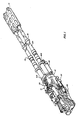
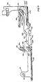
- the gun includes a left hand gun barrel 10L and a right hand gun barrel 10R which are secured to a breach housing 12 of a breech assembly 14.
- the barrels are also constrained by a muzzle clamp assembly 16, a mid- barrel clamp assembly 18, and an aft clamp assembly which is part of a gas drive assembly 22 and is shown in FIG. 1, and in FIGS. 38through 41, for driving the gun, but this gas drive assembly may be deleted and the externally powered drive assembly shown in FIGS. 42 and 43 or the externally powered drive assembly shown in FIG. 44 may be substituted therefor.
- the breech housing 12 is fixed to a receiver housing 26 in a receiver assembly 28.
- a hammer assembly 30 is also fixed to the breech housing 12.
- the breech and receiver housings may be considered together to be the classical "receiver".
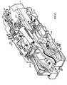
- the operating mechanism 32 is mainly disposed within the receiver housing 26 and is included in the receiver assembly 28.
- This operating mechanism includes a rocking lever 34 which is fixed to a central post 36, and which post is journaled for oscillation to the receiver housing 26.
- the rocking lever 34 has a left arm 34L to which is fixed a left post 38L which is journaled to the forward end of a left link 40L, and has a right arm (not visible) to which is fixed a right post (not visible) which is journaled to the forward end of a right link 40R.
- the aft end of the left link 40L is journaled to a left post 42L which is fixed to a left slider 44L.
- the aft end of the right link 40R is journaled to a right post (not visible) which is fixed to a right slider 44R which is identical to the left slider 44L.
- the aft end of each link 40UR has a projection 40P which is captured in a respective notch in the respective slider 44UR to capture the link to its respective post 42UR.
- An additional post 4E is fixed to the rocking lever 34 and is journaled to the forward end of a feeder arm 48.
- the aft end of the feeder arm 48 has a post (not visible) to which is pivotally journaled a tail slider 52.
- the aft end of the slider has a cross-piece 54 which rides in a channel 56 in the receiver housing 26.
- the forward end of the slider 52 has a cam driver 58 with two mutually spaced apart upstanding arms which terminate in mutually opposed cam driving elements 60L and 60R.
- the cam driver 58 also has a pair of slots 62L and 62R which ride on a pair of tracks (not visible) in the receiver housing. The cam driver 58 is thereby constrained to rectilinear reciprocating movement when driven by the feeder arm 45 whose forward end is free to oscillate laterally while reciprocated fore and aft by the rocking lever 34.
- the operating mechanism also includes a left forward stripper 64L, a right forward stripper 64R, a left aft stripper 66L and a right aft stripper 66R.
- the forward strippers are disposed in respective vertical passageways 68L and 68R in the breech housing 12 and 70L and 70R in the receiver housing 26.
- the aft strippers are disposed in respective vertical passageways (not visible) in the receiver housing 26.
- Each forward stripper includes a base portion 74 and two upstanding arms 76L and 76R each having a respective, inwardly directed lug 78L and 78R, and a hammer upper camming surface 79U and a hammer lower camming surface 79D.
- Each base 74 of each forward stripper has a respective diagonally downwardly facing cam 80C and a part of diagonally-upwardly facing cam surfaces 82UR.
- Each aft stripper 66 has a respective upwardly directed lip 84, a diagonally-downwardly facing cam surface 86C and a pair of diagonally-upwardly facing cam surfaces 88UR.
- Each of the sliders 44UR has a transverse slot 90 in its forward end which receives a disk 92UR on the end of a respective piston rod 94UR in the gas drive assembly 22. As each piston rod is reciprocated by the gas drive assembly it reciprocates the thereto engaged slider. The two sliders, by means of the respective links 40UR, oscillate the rocking lever 34 about its central post 36.
- Each of the sliders 44UR has a respective diagonally-upwardly facing cam surface 96C adapted to drive the stripper cam surface 80C upwardly to bring the respective forward stripper up to engage the nose of a round which is to be stripped from its link, and has a diagonally-upwardly facing cam surface 98C adapted to drive the stripper cam surface 86C to bring the respective aft stripper up to engage the base of a round which is to be stripped from its link.
- Each of the sliders 44UR has a respective pair of diagonally-downwardly facing cam surfaces 100UR adapted to drive the respective pair of forward stripper cam surfaces 82UR downwardly to bring the respective stripper downwardly, and has a respective pair of diagonally-downwardly facing cam surfaces 102UR adapted to drive the respective pair of stripper cam surfaces 88UR downwardly to bring the respective aft cam stripper downwardly, the motion of the strippers being required before the breech bolt begins its ram stroke.
- Each of the sliders 44UR has a respective pair of diagonally-downwardly directed cam surface 104UR to drive the respective pair of stripper cam surfaces 82UR further downwardly to bring the respective forward stripper further down into its gun bolt locking disposition, and has a respective pair of downwardly facing cam surfaces 106UR to over-ride a respective pair of upwardly facing cam surfaces 108UR on the forward stripper to maintain such forward stripper in its gun bolt locking disposition.
- Each of the sliders 44UR has a respective cam surface 108C to drive the respective stripper cam surface 80C upwardly to bring the respective forward stripper out of its gun bolt locking disposition.
- Each of the sliders 44UR has a respective upstanding ear portion 110 with a cross bore 112 therethrough, and has a forward pair of outwardly-laterally-extending tracks 114UR and an aft pair of outwardly-laterally-extending tracks 116UR. These tracks ride in fore-aft extending respective tracks (not visible) in the receiver housing 26.
- Each of a pair of gun bolt assemblies 118UR respectively includes a bolt head assembly 120U R, a connecting link 122UR and an accelerator link 124UR.
- Each bolt head assembly 120UR includes a bolt head body 126UR having an interior cavity 128 with an aftwardly directed opening 130 to the body aft face 132, an upwardly directed opening 134 to the body top face 136, and a forwardly directing opening 138 to the body front face 140.
- Each body 126UR also has a pair of upper extractor lugs 142UR and a pair of lower extractor lugs 144UR which are adapted to enter the extrator groove 146 forward of the base 148 of the cartridge cas 150 of rounds 152 of ammunition.
- Each body also has a pair of mutually spaced apart, upwardly directed ears 154UR with a respective cross-bore 156UR.
- a firing pin 158 is mounted in each bolt head and includes an upper head 160 over lying the bolt top face and extending aftwardly from an elbow 162 with a cross-bore 164 which is pivotally secured between the ears 154UR by a cross-pin 166 through the bores 156U R and 164, a leg 168 extending downwardly from said elbow through the opening 134 into the cavity 128 and terminating in a penetrator 170 extending through the opening 138.
- the bolt head body 126 also has a pair of laterally extending channels 172UR adapted to receive respective tracks (not visible) in the breech housing 12 and the lugs 78UR respectively in the respective forward stripper 64UR.
- the four aft surfaces 173a, b, c and d serve as locking lugs for the bolt head body 126 and abut adjacent surfaces 174a, b, c and d (174b, c and d not visible) on the breech housing which serve as locking lugs for the breech.
- the bolt head body is shifted vertically into lock and unlock disposition by the respective forward stripper through the engagement of forward stripper lugs 78UR with the bolt head body channels 172UR.
- Each connecting link 122UR has a forward end with a cross-bore 175 disposed within the cavity 128 and which is pivotally held to the bolt body 126 by a cross-pin 176 disposed in the cross-bore 175 and in two aligned bores (not visible) in the bolt body 126.
- the link has an aft end with a quick release assembly 178 shown in FIG. 7.
- Each accelerator link 124UR has a lower portion terminating in a forwardly extending clevis 180 having a central slot 182 defined by the two ears of the clevis 180 and having a cross-bore 184UR through each of the ears respectively.
- the aft ear 110UR of the respective slider 44UR is disposed within the slot 182 and is pivotally held to the clevis by a cross-pin 186 through the cross-bore 112 and the cross-bores 184UR.
- the lower portion also has a cross-bore (not visible) through which passes a shaft 190 which has an outer hand cam roller 192 integral therewith and an inner hand cam roller 194 journaled thereon.
- cam rollers ride on respective S-shaped cam surfaces 196UR in the receiver housing 26 which has upper and lower outer-upstanding lips 198 and 200 to preclude the assembly of cam rollers 192 and 194 from leaving the cam surfaces.
- Respective notches 202 and 204 are cut in the lips to permit the transverse entry of the rollers when the link is assembled into the housing.
- Each accelerator link 124UR has an upper portion terminating in a upwardly extending clevis 206 having a central slot 208 defined by the two ears of the clevis and having cross-bores 210UR through each of ears respectively.
- a cross-pin 212 is disposed through the cross-bores 210UR across the slot 208 and has a cross-notch 214 of semi-circular transverse cross-section.
- the quick release assembly 178 interengages the clevis 206 and cross-pin 212 to provide a pivotable joint between the accelerator link 124 and the connecting link 122.
- the quick release assembly 178 includes a cross-bore 216 through the aft end portion of the connecting link and a notch cutting away a corner of the end portion to the cross-bore 216 to provide an aft face 218 which is tangential to the circumference of the cross-bore 216 and an upper face 220 which is perpendicular to the aft face 218 and has an opening equal to the diameter of the pin.
- These two faces and the remaining circumferential wall of the cross-bore will pass the cross-pin 212 when the end portion of the connecting link is moved into the proximal portion of the slot 208 and will nest the cross-pin 212 into the cross-bore 216 when the end portion is moved towards the distal portion of the slot 208.
- the end portion has a longitudinal blind bore 222 in which are disposed a helical compression spring 224 and a plunger-rod 226.
- the plunger-rod has a longitudinally extending flat 228 which passes a cross-pin 230 which is fixed in a transverse bore in the aft end portion of the connecting link through the longitudinal blind bore 222.
- the compression spring 224 biases the plunger-rod 226 aftwardly, within the constraint provided by the flat 228 and the cross-pin 230, so that the distal end of the plunger-rod 226 is disposed within the notch 214 of the cross-pin 212 to capture the cross-pin 212 to the quick release assembly 178.
- the plunger-rod 226 is pressed, against the bias of the spring 224, out of the notch 214 and the quick release assembly is unhooked from the cross-pin 212.
- the accelerator link 124 in conjunction with the S-shaped cam surface 196, converts the motion of the slider 44 provided by the gun drive mechanism into the motion required for the operating cycle of the gun bolts.
- An ammunition feeder assembly 234 is disposed within the receiver housing 26 and includes a transverse guide 236 having a forward groove 238 and an aft groove 240 to guide the forward and aft ends of links 241 which form the ammunition belt, here shown as a left hand feed.
- the links are of the side stripping type wherein each round of ammunition provides a pivotal interconnection between immediately adjacent links.
- a four toothed sprocket 242 is fixed to a longitudinally extending forward feeder shaft 244 whose forward and aft ends are journaled for rotation in the receiver housing.
- a drum cam 246, having four terminally interconnected helical grooves 248, is splined to an aft shaft 245.
- the aft end of the shaft 244 is slotted to slidably receive the blade forward end of the aft shaft 245 whose aft end is journaled in the longitudinal bore of a one-way clutch 247 which serves as its aft end journal in the receiver housing.
- a helical compression spring 245a is captured between a plunger 245b held by a crosspin 245c to bias the aft shaft blade into the slot.
- the blade may be manually withdrawn to permit reverse rotation of the forward shaft to permit the ammunition belt to be manually withdrawn.
- the cam driving elements 60L and 60R of the cam driver 58 ride the grooves 248.
- this fourth round is chambered into the left hand gun barrel, while the sprocket aligns the third round with the right hand gun bolt and strips it from its link.
- the above described procedure can be done in a right side feed operation by reversing the sprocket, the drum cam, and the one way clutch.
- the tips of the teeth of the sprocket are spaced apart by a pitch which is slightly greater than the normal, unstressed pitch of the belt of ammunition to accommodate any stretching of the belt.
- the stripping of each round is performed by the respective set of forward and aft strippers while the ramming of such round is performed by the respective gun bolt and an array of guides in the breech assembly 14.
- the guide array includes a center guide 250, a left guide 252L and a right guide 252R as well as the ammunition link and guides machined in the breech housing 12.
- the center guide 250 is pivotally mounted on a pin 253 to a longitudinally extending web 254 in the breech housing 12.
- the guide has a downwardly directed pocket 256 formed therein with an outwardly extending overhanging lip 258.
- a detent plate 2360 is disposed in the pocket and has a forwardly extending foot 262 under the lip 258 and a helical compression spring 264 captured in an upwardly directed pocket 266.
- the spring biases the detent plate upwardly about the transverse pivot axis formed by the foot and the lip.
- the detent plate also has a upwardly extending nose 268 adapted to enter either of two slots (not visible) in the breech housing 12 to retain the center guide in either of its swung left or swung right dispositions, and a left and right cam surface 272UR which may be overridden by an aftwardly moving bolt head to pivot the detent plate downwardly to disengage its nose 268 from one of said slots.
- the center guide also has a pocket 274C which receives a downwardly extending projection (not visible) in the breech housing 12 to limit the swing to the left or right of the center guide; and has a left and a right cam surface 276UR adapted to be abutted by the aftwardly moving bolt head, after the bolt head has released the detent, whereby the bolt head can swing the center guide to the right or left respectively.
- the center guide also has a left and a right concave upper guide surface 278UR and a left and a right concave lateral guide surface 180Uk.
- the left and right side guides 252UR each include a forward side guide 282 and an aft side guide 284 which are both pivotally journaled on a pin 286 to the breech housing 12.
- a compression spring 228 is captured in a concave groove in a slot in an aftwardly extending leg 294 of the forward side guide 282 and biases a forwardly extending foot 296 of the aft side guide 284 which extends into the slot.
- the aft tips of the leg 294 are thus biased against upper and lower stops 298U/L on the aft side guide 284.
- FIGS. 13 and 14 show the left gun bolt head assembly 120L, the left side guide assembly 252L, the center guide assembly 250, the left aft stripper 66L and the left forward stripper 64L in their respective feed dispositions.
- the left gun bolt head 120L is in rear dwell and abuts the aft end of the aft side guide 284 swinging this aft end outwardly (here seen clock-wise) about the pivot 286, and via the spring 288, swinging the forward end of the forward side guide 282 inwardly over the round which is vertically aligned with the left hand gun barrel and still in its link 241 in the transverse guide 236 under the control of the sprocket 242.
- the gun bolt while moving aft towards rear dwell had over-ridden the cam surface 272L to disengage the detent plate 260 from the left hand slot in the housing, and while the detent plate is disengaged, had aubbed the lateral cam surface 276L to swing the center guide assembly 250 about its pivot 253 to its swung-right disposition, whereat the detent plate engages the right hand slot in the housing.
- the left slider 44L has been moving aftwardly and is now about three-fourths aft.
- the aft and forward strippers 66L and 64L are below the round.
- FIGS. 15 and 16, and also FIG. 10, show the round stripped out of its link by the aft and forward strippers 66L and 64L which were raised by the still aftwardly moving left slider 44L.
- the left gun bolt head 120L remains in rear dwell and an upper portion of the base of the cartridge case is now on a lower portion of the face of the gun bolt, with the extractor disk of the case engaged by the lower extractor lugs 144UR.
- Upward movement of the base of the case is limited by a pair of mutually facing surfaces 277LL and 277LR, while the shoulder of the case is limited by the lower face of the forward side guide 282L.
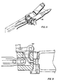
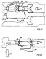
- FIGS. 17 and 18 show the round being carried forward by the left gun bolt head which is carried forward by the left slider moving forward, via the accelerator link.
- the round is nosed upwardly at about 1° to the axis of the gun barrel and is guided by the left concave lateral guide surface 280L on the center guide assembly and a concave guide surface 281L in the breech housing 12 which slope upwardly at about 1° to the axis of the gun barrel.
- An additional pair of mutually facing, upward sloping guide surfaces 281 LL and 281 LR are positioned further forward on the breech housing 12 to continue guidance of the round as it is moved forward.
- FIGS. 19 and 20 show the round chambered and locked into the left gun barrel by the left gun bolt head which has been carried forward by the still moving forward left slider.
- the lugs 78UR of the left forward stripper respectively entered the channels 172UR grooves in the bolt head, and, thereafter, the left slider pulled the left forward stripper, and therewith the left bolt head, downwardly, into the bolt head locked disposition.
- the right gun bolt head moving aftwardly has disengaged the detent and switched the center guide assembly into its left hand disposition.
- FIGS. 21 and 22 show the fired cartridge case during extraction, (after the chambered and locked round has been fired).
- the extractor disk of the fired cartridge case rides onto the concave upper guide surace 278L of the center guide assembly and is thereby cammed upwardly along the face of the gun bolt so that while initially engaged with the lower extractor lugs 144UR and aligned with a pair of mutually facing, concave guide surfaces 283LL and 283LR in the breech housing 12 which are parallel to and spaced vertically above the axis of the gun barrel, engagement of the extractor disk transfers to the upper extractor lugs 142UR as the bolt moves aftwardly.
- the left bolt head subsequently disengages the detent and shifts the center guide assembly to its right hand disposition as shown in FIG. 23.
- FIGS. 23 and 24 show the fired cartridge case further extracted as the left bolt head continues to travel aftwardly.
- the left bolt head abuts the aft end of the aft side guide 284 swinging this aft end outwardly (here shown clock-wise) about the pivot 286, and via the spring 288, swinging the forward end of the forward side guide 282 inwardly to strike, and spring yield, against the side of the extracted cartridge case, and subsequently to swing in further under and to push upwardly the shoulder of the extracted cartridge case, and overlie the next round which is to be stripped from its link and is lying on the transverse guide 236.
- An ejector guide 270 is bolted to the breech housing and limits upward movement of the base of the round on the bolt face.
- FIGS. 25 and 26 show the fired cartridge case fully extracted, still engaged with the upper extractor lugs of the left bolt head which is in rear dwell, and its base resting on laterally extending trackways (not visible) in the breech housing 12 and on the base of the next round which has been stripped from its link (much as was shown in FIG. 16) and its shoulder resting on the side guide 282L.
- the slider is still moving aft and the center guide assembly is in its right hand disposition.
- FIGS. 27 and 28 show the fired cartridge case being ejected.
- the extractor disk of the fired case is pushed upwardly off the face of the gun bolt by the upper face of the forward side guide 282L and an upper pair of mutually facing, concave guide surfaces 307LL and 307LR in the breech housing, as the gun bolt is moving forward from rear dwell in the disposition substantially as shown in FIGS. 17 and 18.
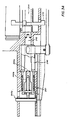
- FIGS. 29 and 30 show the hammer assembly 30 in the on-sear or cocked disposition, while FIGS. 31 and 32 show the off-sear or fired disposition.
- the hammer assembly includes a hammer housing 308 which is secured to the breech housing 12 by two forward bolts 310 and one aft bolt 312.
- the hammer head 314 is integral with a hammer body 316 which has a longitudinal bore 318 and a substantially downwardly directed double clevis 320 and a forward facing concave cam 322 adapted to receive an aftwardly projecting sear 364.
- the hammer body 316 is journaled to the housing 308 by a hammer shaft 326 having a main portion which fits the bore 318, a reduced forward portion which fits a forward bore 328 and an enlarged aft portion which fits an aft bore 330.
- a firing spring housing 332 is secured to the breech housing, as by mutual threads 334.
- the housing contains a helical compression firing spring 336, a spring follower 338 having a socket 340, a connecting link 342 having a knuckle 344 on its lower end riding in the socket 340 and a crossbar 346 on its upper end riding in the double clevis 320.
- a solenoid 348 is bolted to the hammer housing 308 and has an armature 350 which is pulled down into the housing when the solenoid is energized so that the gun may fire. The rate of fire may be controlled by pulsed energization of the solenoid.
- a sear control lever 352 is pivotally mounted to the hammer housing by a cross-pin 354 and has a bifurcated forward end 356 which rides under the head 358 of the armature 350. The aft end of the lever has a nose with a flat face 360 which is substantially perpendicular to its radius to the pivot 354 and also has a sloping face 362.
- the sear pin 364 is disposed in a bore 366 in the hammer housing, and has a flat step 368 which rides under a cross-pin 370 to prevent the sear pin from rotating but which permits limited fore and aft movement of the sear pin.
- the sear pin has a wedge shaped aft end 372 which rides into the forward facing concave cam 322 of the hammer body 316, and has flat transverse face 374 adapted to abut the flat face 360 of the control lever and has a sloping face 376 adapted to be cammed by the sloping face 362 of the control lever.
- a helical compression spring 378 is captured between the hammer housing 308 and the sear control lever 352 and biases the lever 352 into its on-sear disposition as shown in FIG. 29 when the solenoid 348 is deenergized, so that the sloping surface 362 on the aft end of the lever cams against the sloping surface 376 on the forward end of the sear pin to push the sear pin 364 aftwardly until the lever snaps down so that the faces 360 and 374 are in abutment to hold the sear pin aft.
- the solenoid 348 when the solenoid 348 is energized, and pulls in its armature 350 to swing the forward end 356 of the control lever 352 downwardly against the bias of the sear spring 378 and to swing the aft end flat face 360 out of the path of the sear pin 364, the firing spring biases the hammer head downwardly and the forward facing concave cam 322 cams the wedge shaped aft end 372 of the sear pin 364 forwardly, out of the concavity of the cam 322, so that the hammer head is free to swing downwardly.
- FIGS. 33 through 37 The various positions of the hammer head 314 are shown, (looking forward from aft), in FIGS. 33 through 37.
- FIG. 33 shows the hammer head, at the time of firing the right hand gun barrel, impacting the head 160R of the right hand firing pin 158R of the right hand gun bolt head assembly 120R.
- the hammer head is clear of the right forward stripper 64R, the left forward stripper 64L, and the head 160L of the left hand firing pin 158L.
- the hammer head has a left hand safety sear surface 382L and a right hand safety sear surface 382R whose respective function is to ensure that the respective gun bolt head is safely locked, i.e., the locking lugs 173a, b, c and on the aft face of the gun bolt head and the respective locking lugs 174a, b, c and d on the breech housing are adequately, but not totally, mutually engaged, before the hammer head is otherwise clear to be driven fully downwardly to impact the respective firing pin.
- FIG. 34 shows the right hand gun bolt fired and fully unlocked.
- the hammer upper camming surface 79U of the right forward stripper 64R engages a right hand camming surface 380R and as the stripper is raised by the slider 44R, the stripper cams the hammer counter-clockwise against the bias of the firing spring 336.
- the stripper lower camming surface 79D engages the right hand safety sear surface 382R and continues to cam the hammer counter-clockwise as shown in FIG. 35 until the hammer goes over-center as shown in FIG.
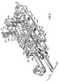
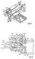
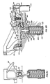
- the gas drive and clearing assembly are shown in their deenergized or cleared disposition in FIGS. 38 and 39, and also shown in part in FIG. 4.
- a detent 386 which is mounted in the receiver housing 26 to slide fore and aft, has an aftwardly extending projection 388 with a depending foot 390 which projects into a recess 392 in the rocking lever 34.
- the recess 392 has an inner arcuate wall 394 which has a left and a right locking surface 396UR.
- the foot 390 has a forward facing locking surface 398 which rides against and along the surfaces 394, 396L and 396R.
- the rocking lever 34 also has a peripheral ridge 400 which terminates in two radially projecting blocking faces 402UR which are respectively adapted to abut against either of two blocking surfaces 404UR on the detent when the locking surface 398 is wedged against either locking surface 396L or 396R.
- the rocking lever 34 is swung fully counter-clockwise beyond the disposition shown in FIG. 4, the detent surface 398 is cammed onto the surface 396R and the detent is pulled aftward and is simultaneously pushed aftward by three parallel springs 446 so that the peripheral face 402R is wedged against the detent surface 404L.
- the detent must move forward.
- rocking lever If such forward movement is precluded, the rocking lever is frictionally locked against rotation, and operation of the operating mechanism of the gun is halted.
- the rocking lever When the rocking lever is swung fully clockwise, and the detent surface 398 is cammed onto the surface 396L, a similar locking action is provided.
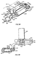
- the gas drive and clearing assembly includes a left and a right cylinder 408UR, each cylinder having a respective piston rod 410UR, each rod having a respective aft end formed at the disk 92UR, each disk adapted to fit the respective slot 90UR in the forward end of the respective slider 44UR.
- the forward ends of the cylinder are connected by a manifold block 414 which has a socket to receive a gas squib, or a plurality of squibs (not shown), whose upper end 416 is threaded to receive an electrical connector to enable the firing of the squib to provide gas under pressure in the manifold and thence to the cylinders.
- a rocker arm 418 is pivotally mounted at 420 to the manifold and is coupled to two pilot rods 422UR which are respectively activated by the piston rods 94UR at the forward end of their stroke to open the respective valve (not shown) in the manifold.
- the right hand pilot rod 422R is driven forward and opens the right hand valve to permit the flow of gas from the squib into the right hand piston 408R and swings the rocker arm 418 to close the left hand valve to preclude the flow of gas into the left hand piston 408L.
- the pistons also have respective gas bleed ports 424U R which are aligned with corresponding gas bleed ports, not shown, in the gun barrels.
- the ports 424 are not controlled by the valves in the manifold and pass gas directly from the fired gun barrel into the respective gas cylinder to drive the respective piston aftwardly to drive the respective slider aftwardly.
- the cylinders have respective forward mounting brackets, 426UR which are bolted to a top clamp bracket 428 by four bolts to form the forward clamp assembly.
- the cylinders have respective aft mounting brackets 425aUR which are bolted to a bracket 430 which is bolted to a top clamp bracket 432.
- a clearing lever 434 has a clevis 436 at its forward end pivotally mounted at 438 to a tab depending from the bracket 430 and has a depending foot 440 at its aft end projecting through a slot 442 in the forward end of the receiver housing 26 adjacent the forward end of the detent 386.
- the detent 386 has three blind bores 444 therein, in each of which is disposed a respective helical compression spring 446 which is captured between the detent and the receiver housing and which biases the detent aftwardly.
- a clearing solenoid 448 is bolted to the bracket 430 and has an armature 450, with a notch 452 in its distal end which captures the clearing lever 434, and a helical compression spring 454 which biases the clearing lever and the armature downwardly.
- the depending foot 440 is disposed immediately forward of the detent 386 and precludes the detent from moving forwardly, which precludes the rocking lever from rotating, and thereby halts the operation of the gun, notwithstanding any gas pressure in either of the cylinders 408UR, thus "safing" the gun by leaving a fired cartridge case in one of the barrels.
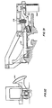
- the clearing solenoid 448 When the clearing solenoid 448 is energized, as shown in FIGS. 40 and 41, it pulls up the armature 450 and the clearing lever 434, against the bis of the spring 454, to swing the depending foot 440 upwardly and out of the way of the detent 386, to permit the detent 386 to move forwardly against the bias of the springs 446, when gas pressure in either of the cylinders tends to cause the rocking lever to rotate, so that the detent thereby permits the rocking lever to rotate, thereby permitting operation of of the gun.
- the safing system which includes the clearing solenoid 448, the clearing lever 434 and the detent 386, remains as shown in FIG. 39 to provide their functions.
- the external drive assembly includes an electric motor 460, fixed to the receiver housing, whose output shaft 462 is fixed to a shaft 464 which is fixed to a lower bevel gear 466.
- the gear 466 is meshed with a lateral bevel gear 468 fixed to a shaft 469 and which is meshed with an upper bevel gear 470, which is journaled for rotation with respect to the shaft 464.
- a lower cam roller 472 is journaled for rotation on a stub shaft 474 which is carried by the lower gear 466.
- An upper cam roller 476 is journaled for rotation on a stub shaft 478 which is carried by the upper gear 470.
- a shaft 480 is splined to the central post 36, shown in FIG. 4, which post is fixed to the rocking lever 34.
- a bifurcated cam follower 482 is fixed to the shaft 480 and its. bifurcation projects between the gears 466 and 470 so that the rollers 472 and 476 may ride into and out of the cleft cam following surface 484 of the bifurcation.
- the shafts 464, 469, and 480 are each respectively supported by stationary journals, (not shown).
- the electric motor 460 drives the shaft 464 with the gear 466 counter-clockwise so that the roller 472 is carried counter-clockwise and swings the bifurcated cam follower 482 with the shaft 480 and the rocking lever 34 clockwise until the roller 472 exits the cleft 484 and the swing of the follower 482 halts.
- the gears 466 and 468 drive the gear 470 clockwise until it enters the cleft 484 and swings the follower 482, and thereby, the rocking lever 34 counter-clock-wise until the roller 476 exits the cleft 484 and the swing of the follower 482 halts until the roller 482 reenters the cleft, and so on.
- FIG. 44 an external drive may be substituted as shown in FIG. 44.
- This external drive assembly includes a double acting cylinder 500 having a piston 502 whose forward end is connecting by a pivotable joint 504 to a journal rod 506 which is journaled on a post 508 which is fixed to and depends from the underside of the rocking lever 34 and is eccentric to the central post 36.
- Aftward movement of the piston 502 pulls the rocking lever through the disposition shown in FIG. 44 to bring the left slider 44L into its aft disposition.
- Forward movement of the piston 502 pushes the rocking lever to bring the right slider 44R into its aft disposition.
Landscapes
- Engineering & Computer Science (AREA)
- General Engineering & Computer Science (AREA)
- Transmission Devices (AREA)
- Portable Nailing Machines And Staplers (AREA)
Claims (15)
dadurch gekennzeichnet, daß
dadurch gekennzeichnet, daß
dadurch gekennzeichnet, daß
dadurch gekennzeichnet, daß
dadurch gekennzeichnet, daß
dadurch gekennzeichnet, daß
dadurch gekennzeichnet, daß
dadurch gekennzeichnet, daß
dadurch gekennzeichnet, daß
dadurch gekennzeichnet, daß
dadurch gekennzeichnet, daß
Applications Claiming Priority (4)
| Application Number | Priority Date | Filing Date | Title |
|---|---|---|---|
| US793013 | 1985-10-30 | ||
| US06/793,013 US4700608A (en) | 1985-10-30 | 1985-10-30 | Machine gun |
| US878470 | 1985-12-18 | ||
| US06/878,470 US4726278A (en) | 1985-12-18 | 1985-12-18 | Drive for a machine gun |
Related Child Applications (4)
| Application Number | Title | Priority Date | Filing Date |
|---|---|---|---|
| EP88115215A Division EP0313793A3 (de) | 1985-10-30 | 1986-10-17 | Maschinenkanone |
| EP88115214A Division EP0306061A3 (de) | 1985-10-30 | 1986-10-17 | Fremdantrieb für eine Maschinenkanone |
| EP88115214.4 Division-Into | 1988-09-16 | ||
| EP88115215.1 Division-Into | 1988-09-16 |
Publications (2)
| Publication Number | Publication Date |
|---|---|
| EP0220630A1 EP0220630A1 (de) | 1987-05-06 |
| EP0220630B1 true EP0220630B1 (de) | 1990-05-02 |
Family
ID=27121356
Family Applications (2)
| Application Number | Title | Priority Date | Filing Date |
|---|---|---|---|
| EP86114433A Expired EP0220630B1 (de) | 1985-10-30 | 1986-10-17 | Maschinenwaffe |
| EP88115214A Withdrawn EP0306061A3 (de) | 1985-10-30 | 1986-10-17 | Fremdantrieb für eine Maschinenkanone |
Family Applications After (1)
| Application Number | Title | Priority Date | Filing Date |
|---|---|---|---|
| EP88115214A Withdrawn EP0306061A3 (de) | 1985-10-30 | 1986-10-17 | Fremdantrieb für eine Maschinenkanone |
Country Status (3)
| Country | Link |
|---|---|
| EP (2) | EP0220630B1 (de) |
| DE (1) | DE3670902D1 (de) |
| IL (1) | IL80363A0 (de) |
Families Citing this family (1)
| Publication number | Priority date | Publication date | Assignee | Title |
|---|---|---|---|---|
| FR2721386B1 (fr) * | 1994-06-16 | 1996-08-14 | Giat Ind Sa | Ensemble de transmission destiné à une arme automatique. |
Family Cites Families (6)
| Publication number | Priority date | Publication date | Assignee | Title |
|---|---|---|---|---|
| FR491908A (fr) * | 1916-01-25 | 1919-06-23 | Alexander Miller Brotherston | Perfectionnements aux mitrailleuses |
| US1477115A (en) * | 1920-09-30 | 1923-12-11 | Gast Carl | Double-barreled machine gun with recoiling barrels |
| GB577338A (en) * | 1944-02-18 | 1946-05-14 | George William Patchett | Improvements in power driven guns or cannons |
| US2972286A (en) * | 1950-04-18 | 1961-02-21 | Frank R Marquardt | Rapid fire gun with two barrels and a plurality of firing chambers |
| US4154142A (en) * | 1977-09-06 | 1979-05-15 | The United States Of America As Represented By The Secretary Of The Army | Externally powered carrier |
| DE3208942C2 (de) * | 1982-03-12 | 1986-02-06 | Rheinmetall GmbH, 4000 Düsseldorf | Maschinenkanone mit zwei zum Vor- und Rücklauf nebeneinander in einem Waffengehäuse angeordneten Waffenrohren |
-
1986
- 1986-10-17 DE DE8686114433T patent/DE3670902D1/de not_active Expired - Lifetime
- 1986-10-17 EP EP86114433A patent/EP0220630B1/de not_active Expired
- 1986-10-17 EP EP88115214A patent/EP0306061A3/de not_active Withdrawn
- 1986-10-19 IL IL80363A patent/IL80363A0/xx unknown
Also Published As
| Publication number | Publication date |
|---|---|
| IL80363A0 (en) | 1987-01-30 |
| EP0306061A2 (de) | 1989-03-08 |
| EP0220630A1 (de) | 1987-05-06 |
| DE3670902D1 (de) | 1990-06-07 |
| EP0306061A3 (de) | 1990-04-18 |
Similar Documents
| Publication | Publication Date | Title |
|---|---|---|
| US2951424A (en) | Gas operated bolt and carrier system | |
| US4562659A (en) | Automatic firearm | |
| US4272902A (en) | Fire-arms | |
| US4700608A (en) | Machine gun | |
| JP2557813B2 (ja) | 二連ボルトアクション連発銃 | |
| US3013355A (en) | Firearm breech bolt mechanism with a bolt stop | |
| US4481858A (en) | Single barrel externally powered gun | |
| DE3021200A1 (de) | Feuerwaffe mit einem schutzsystem gegen verspaetetes losgehen oder nachzuenden | |
| IL39442A (en) | Bolt assembly having a collar rotatable thereon to actuate the bolt lock and sear the firing pin and gun comprising such assembly | |
| EP2359084A1 (de) | Antrieb und schnellstopp für eine waffe mit vorzugsweise linearer verschluss- bzw. munitionszuführung | |
| EP2759798A2 (de) | Verschlusssystem für eine fremd oder eigen angetriebene Waffe | |
| US4841835A (en) | Safety apparatus for an externally powered firing weapon | |
| US4128040A (en) | Blank firing adapter | |
| US4418607A (en) | Single barrel externally powdered gun | |
| EP0111240A2 (de) | Sicherheitsvorrichtung an einem fremdangetriebenen Geschütz | |
| US4619184A (en) | Gas actuated pistol | |
| KR20220049001A (ko) | 무기 시스템 및 노리쇠 | |
| US3380341A (en) | Safing means for high rate of fire multi-barrel automatic weapon | |
| DE3712905A1 (de) | Maschinenwaffe mit schusskontrolle | |
| US4328737A (en) | Ammunition feeder for a gun | |
| EP0107920B1 (de) | Feuerwaffe | |
| EP0220630B1 (de) | Maschinenwaffe | |
| US3788191A (en) | Burst firing, single barrel, armament | |
| US2353118A (en) | Gun | |
| EP0313793A2 (de) | Maschinenkanone |
Legal Events
| Date | Code | Title | Description |
|---|---|---|---|
| PUAI | Public reference made under article 153(3) epc to a published international application that has entered the european phase |
Free format text: ORIGINAL CODE: 0009012 |
|
| AK | Designated contracting states |
Kind code of ref document: A1 Designated state(s): CH DE FR GB LI SE |
|
| 17P | Request for examination filed |
Effective date: 19871016 |
|
| 17Q | First examination report despatched |
Effective date: 19880525 |
|
| GRAA | (expected) grant |
Free format text: ORIGINAL CODE: 0009210 |
|
| AK | Designated contracting states |
Kind code of ref document: B1 Designated state(s): CH DE FR GB LI SE |
|
| ET | Fr: translation filed | ||
| REF | Corresponds to: |
Ref document number: 3670902 Country of ref document: DE Date of ref document: 19900607 |
|
| PLBE | No opposition filed within time limit |
Free format text: ORIGINAL CODE: 0009261 |
|
| STAA | Information on the status of an ep patent application or granted ep patent |
Free format text: STATUS: NO OPPOSITION FILED WITHIN TIME LIMIT |
|
| 26N | No opposition filed | ||
| PGFP | Annual fee paid to national office [announced via postgrant information from national office to epo] |
Ref country code: SE Payment date: 19910918 Year of fee payment: 6 |
|
| PGFP | Annual fee paid to national office [announced via postgrant information from national office to epo] |
Ref country code: CH Payment date: 19910920 Year of fee payment: 6 |
|
| PGFP | Annual fee paid to national office [announced via postgrant information from national office to epo] |
Ref country code: GB Payment date: 19910925 Year of fee payment: 6 |
|
| PGFP | Annual fee paid to national office [announced via postgrant information from national office to epo] |
Ref country code: FR Payment date: 19911023 Year of fee payment: 6 |
|
| PGFP | Annual fee paid to national office [announced via postgrant information from national office to epo] |
Ref country code: DE Payment date: 19911101 Year of fee payment: 6 |
|
| PG25 | Lapsed in a contracting state [announced via postgrant information from national office to epo] |
Ref country code: GB Effective date: 19921017 |
|
| PG25 | Lapsed in a contracting state [announced via postgrant information from national office to epo] |
Ref country code: SE Effective date: 19921018 |
|
| PG25 | Lapsed in a contracting state [announced via postgrant information from national office to epo] |
Ref country code: LI Effective date: 19921031 Ref country code: CH Effective date: 19921031 |
|
| GBPC | Gb: european patent ceased through non-payment of renewal fee |
Effective date: 19921017 |
|
| PG25 | Lapsed in a contracting state [announced via postgrant information from national office to epo] |
Ref country code: FR Effective date: 19930630 |
|
| REG | Reference to a national code |
Ref country code: CH Ref legal event code: PL |
|
| PG25 | Lapsed in a contracting state [announced via postgrant information from national office to epo] |
Ref country code: DE Effective date: 19930701 |
|
| REG | Reference to a national code |
Ref country code: FR Ref legal event code: ST |
|
| EUG | Se: european patent has lapsed |
Ref document number: 86114433.5 Effective date: 19930510 |