EP0220556B1 - Combustion augmented plasma amplification system - Google Patents
Combustion augmented plasma amplification system Download PDFInfo
- Publication number
- EP0220556B1 EP0220556B1 EP86113924A EP86113924A EP0220556B1 EP 0220556 B1 EP0220556 B1 EP 0220556B1 EP 86113924 A EP86113924 A EP 86113924A EP 86113924 A EP86113924 A EP 86113924A EP 0220556 B1 EP0220556 B1 EP 0220556B1
- Authority
- EP
- European Patent Office
- Prior art keywords
- dielectric
- oxidizer
- chamber
- fuel
- accordance
- Prior art date
- Legal status (The legal status is an assumption and is not a legal conclusion. Google has not performed a legal analysis and makes no representation as to the accuracy of the status listed.)
- Expired - Lifetime
Links
- 230000003321 amplification Effects 0.000 title description 6
- 238000003199 nucleic acid amplification method Methods 0.000 title description 6
- 238000002485 combustion reaction Methods 0.000 title description 4
- 230000003190 augmentative effect Effects 0.000 title description 3
- 239000007800 oxidant agent Substances 0.000 claims abstract description 34
- 239000000446 fuel Substances 0.000 claims abstract description 29
- 239000012530 fluid Substances 0.000 claims description 13
- 239000012528 membrane Substances 0.000 claims description 8
- 239000004215 Carbon black (E152) Substances 0.000 claims description 5
- MHAJPDPJQMAIIY-UHFFFAOYSA-N Hydrogen peroxide Chemical compound OO MHAJPDPJQMAIIY-UHFFFAOYSA-N 0.000 claims description 5
- 239000004020 conductor Substances 0.000 claims description 5
- 229930195733 hydrocarbon Natural products 0.000 claims description 5
- 150000002430 hydrocarbons Chemical class 0.000 claims description 5
- 229920000642 polymer Polymers 0.000 claims description 5
- 239000000463 material Substances 0.000 claims description 4
- MYMOFIZGZYHOMD-UHFFFAOYSA-N Dioxygen Chemical group O=O MYMOFIZGZYHOMD-UHFFFAOYSA-N 0.000 claims description 3
- WHXSMMKQMYFTQS-UHFFFAOYSA-N Lithium Chemical compound [Li] WHXSMMKQMYFTQS-UHFFFAOYSA-N 0.000 claims description 3
- 229910000103 lithium hydride Inorganic materials 0.000 claims description 3
- 239000000203 mixture Substances 0.000 claims 1
- 230000001141 propulsive effect Effects 0.000 claims 1
- 238000006243 chemical reaction Methods 0.000 abstract description 9
- 230000001133 acceleration Effects 0.000 abstract description 2
- 239000000470 constituent Substances 0.000 abstract 1
- 238000005516 engineering process Methods 0.000 description 8
- 239000007788 liquid Substances 0.000 description 8
- 239000003380 propellant Substances 0.000 description 8
- 239000007789 gas Substances 0.000 description 6
- -1 polyethylene Polymers 0.000 description 5
- 239000004698 Polyethylene Substances 0.000 description 4
- 229920000573 polyethylene Polymers 0.000 description 4
- 238000004891 communication Methods 0.000 description 2
- 238000002347 injection Methods 0.000 description 2
- 239000007924 injection Substances 0.000 description 2
- 238000004519 manufacturing process Methods 0.000 description 2
- VGGSQFUCUMXWEO-UHFFFAOYSA-N Ethene Chemical compound C=C VGGSQFUCUMXWEO-UHFFFAOYSA-N 0.000 description 1
- 239000005977 Ethylene Substances 0.000 description 1
- GRYLNZFGIOXLOG-UHFFFAOYSA-N Nitric acid Chemical compound O[N+]([O-])=O GRYLNZFGIOXLOG-UHFFFAOYSA-N 0.000 description 1
- 230000001668 ameliorated effect Effects 0.000 description 1
- 230000015556 catabolic process Effects 0.000 description 1
- 238000011109 contamination Methods 0.000 description 1
- 230000001939 inductive effect Effects 0.000 description 1
- 229910010272 inorganic material Inorganic materials 0.000 description 1
- 239000011147 inorganic material Substances 0.000 description 1
- 239000012212 insulator Substances 0.000 description 1
- 229910017604 nitric acid Inorganic materials 0.000 description 1
- 239000011368 organic material Substances 0.000 description 1
- 230000003647 oxidation Effects 0.000 description 1
- 238000007254 oxidation reaction Methods 0.000 description 1
- 239000008188 pellet Substances 0.000 description 1
- 239000007787 solid Substances 0.000 description 1
- 239000004449 solid propellant Substances 0.000 description 1
- 230000002459 sustained effect Effects 0.000 description 1
Images
Classifications
-
- F—MECHANICAL ENGINEERING; LIGHTING; HEATING; WEAPONS; BLASTING
- F41—WEAPONS
- F41B—WEAPONS FOR PROJECTING MISSILES WITHOUT USE OF EXPLOSIVE OR COMBUSTIBLE PROPELLANT CHARGE; WEAPONS NOT OTHERWISE PROVIDED FOR
- F41B6/00—Electromagnetic launchers ; Plasma-actuated launchers
-
- F—MECHANICAL ENGINEERING; LIGHTING; HEATING; WEAPONS; BLASTING
- F41—WEAPONS
- F41A—FUNCTIONAL FEATURES OR DETAILS COMMON TO BOTH SMALLARMS AND ORDNANCE, e.g. CANNONS; MOUNTINGS FOR SMALLARMS OR ORDNANCE
- F41A1/00—Missile propulsion characterised by the use of explosive or combustible propellant charges
- F41A1/04—Missile propulsion using the combustion of a liquid, loose powder or gaseous fuel, e.g. hypergolic fuel
Definitions
- This invention has to do with an apparatus for the generation of pressure amplification suitable for use in projecting a projectile.
- a controlled chemical reaction is sustained by precisely controlling the power applied to a fuel delivering plasma generator in communication with a source of oxidizer fluid. Upon reaction of the fuel and the oxidizer, or simply the oxidation of the plasma, pressure in the reaction chamber is dramatically increased resulting in sufficient pressure to power a projectile at significant velocity.
- This invention draws from the combined technology of liquid propellant propulsion technology and electrothermal propulsion technology neither of which teach this hybrid combination.
- liquid propellant technology one or more fluids can be combined to generate a chemical reaction that produces pressure to power a projectile.
- the metering and mixing of the two fluids is difficult to control and therefore is subject to the risk of catastrophic failure or at least erratic performance.
- mechanical means require seal and metering technology which is unreliable and so expensive as to be unjustifiable in a high production environment.
- the electrothermal propulsion system is a new technology that utilizes the electrical output of an inductive or capacitive network which condenses a pulse from an electrical generating source and energizes the cathode of the system.
- Dielectric breakdown plasma is directed to a chamber containing an inert working fluid which is vaporized to provide gas pressure to eject or propel a projectile. All of the projectile energy is derived from the electrical power pulse.
- the resulting device has the serious drawback of being extremely bulky due to the excessive size of the electrical power supply which makes the unit difficult to integrate with desirable platforms for use as projectile launchers.
- US-A-4 376 406 discloses a firearm using a projectile fitted to a convential cartridge case filled with a solid propellant.
- a piston and cylinder arrangement containing a liquid propellant.
- the gas pressure driving the projectile acts on said piston via the first port and this drives the piston forwardly to compress the liquid propellant against a check valve that then moves forward to uncover a second port leading back to the gun barrel.
- the compressed liquid propellant is forced through this second port and enters the gun barrel just as the projectile has passed the point of entry of the liquid fuel into the gun barrel.
- the liquid propellant injected into the barrel mixes with the conventially produced propellant gases and combusts to produce additional gas to accelerate the projectile to a higher velocity.
- the propulsion or pressure amplification system disclosed herein is a hybrid unit combining the liquid propellant and the electrothermal technologies resulting in an efficient propulsion unit that has ameliorated the disadvantages of those technologies.
- the instant invention is a combustion augmented plasma (CAP) device that uses a plasma cartridge to controllably inject fuel into an oxidizer chamber.
- the plasma cartridge functions as an electric feed pump whose injection rate is controlled by the power applied to the plasma cartridge.
- the chemical reaction of the oxidizer with fuel supplied by the plasma feed pump provides the principal source of energy for generation or amplification of pressure.
- the uses of such generated pressure are several such as the production of an impact force or the generation of a controlled pressure increase for use in propelling a projectile.
- a preferred embodiment of this invention incorporates the use of the pressure amplification property in a gun system (hereinafter "CAP gun").
- CAP gun a gun system
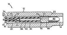
- Such a system is shown in the drawing figure wherein a projectile, its host cartridge and a gun chamber and barrel environment are shown in a section view and indicated generally by 10.
- the cartridge receiver 12 is aligned in a conventional manner with the gun barrel 14.
- the receiver 12 includes a first counterbore 16 providing a cartridge stop ledge 20 to correctly locate the cartridge 24 in the receiver chamber 12.
- the bore of the receiver chamber extends to a ledge 22 which defines the inner end of the barrel portion 14.
- the cartridge 24 is comprised of an outer metallic housing having a first chamber formed with a dielectric retaining shoulder 32.
- the dielectric 40 extends from an end portion 42 extending outwardly from the outer metallic housing to a point at an innermost end 34 of the dielectric where the metallic housing has an inwardly extending projection 52.
- a capillary 36 is provided in the dielectric 40 and extends through the dielectric to provide a storage location for a further dielectric 44 as well as a first conductive means 46.
- the first conductive means 46 can be an anode or cathode and in a preferred embodiment is a cathode connected to an electrical power source (not shown) which in a preferred embodiment is a pulse forming network (PFN) of a conventional type.
- PPN pulse forming network
- the inner end portion of the first conductive means 46 is provided with the enlarged head portion providing a shoulder 50 that contacts a shoulder 32 of the capillary 36 in the dielectric 40 and prevents the first conductive means 46 from being forced out the end of the cartridge.
- a shoulder 26 formed by the end portion 42 abuts against the outer end of the metallic housing 24.
- the capillary 36 inboard of the end of the first conductive means 46 extends from the first conductive means 46 to and through the inwardly extending projection 52 of the metallic housing whereby an orifice or a gate means is formed by and in the inwardly extending projection.
- the innermost end of the capillary 36 is sealed with a membrane 54. This membrane prevents contamination from reaching the further dielectric 44 in the capillary 36.
- the first chamber of the cartridge or fuel chamber thereof is a plasma generator when supplied with electrical energy from the first conductive means 46 to the inwardly extending projection 52 of the cartridge which is a second conductive means.
- a second chamber 56 of the cartridge is an oxidizer containing chamber or a fluid containing chamber containing energetic fluid, that is to say a fluid capable of releasing energy, and being a source thereof.
- the energetic fluid is in a preferred embodiment, an oxidizer means which would be in direct communication with the further dielectric 44 if not for the membrane 54. The energetic fluid will release its energy when it reacts with a plasma gas as explained further on.
- a projectile 60 will be positioned in the barrel portion of gun and typically would abut a sealed end of the oxidizer containing chamber. Alternative embodiments are contemplated where the projectile is integral with the cartridge.
- outer metallic housing 24, or second conductive means is used as an anode and the first conductive means 46 is a cathode.
- the further dielectric 44 is a polyethylene providing a first resistance contained in the capillary 36 between the inboard end of the first conductive means and the membrane 54.
- the dielectric 40 is also of polyethylene. The dielectric 40 is concentrically configured inside the outer metallic housing and is formed with the capillary 36 as shown in the drawing figure.
- the oxidizer means in this preferred embodiment is 70% hydrogen peroxide (H 2 O2) and is contained between the, membrane 54 and the projectile 60. If the projectile is separate from the cartridge then a membrane will be provided to seal the end of the cartridge.
- the pulse forming network which is the power supply, is designed such that it can produce sufficient energy, in a small plasma generator on the order of 10-100 Kilovolts, to bridge the gap through the further dielectric 44 and decompose and partially ionize the further dielectric and a portion of the dielectric 40 by radiant and convective heat transfer to produce a plasma which will form a plasma jet to feed a fuel of partially ionized ethylene to the oxidizer means containing chamber 56.
- the plasma temperature will be greater than the temperature in the oxidizer chamber in order to ensure flow from the fuel chamber of the cartridge into the oxidizer chamber and not the other way around. In one embodiment a plasma temperature of 10,000°K would be desired.
- the hot jet of decomposed and partially ionized polyethylene fuel will be injected into the oxidizer chamber at a velocity of several thousand meters/ sec which will cause turbulent mixing of the fuel and the oxidizer creating a very large surface area which combined with the high temperature will make the reaction in the oxidizer chamber proceed instantly.
- the reaction can be controlled by metering the availability of fuel in the oxidizer chamber which can be accomplished by varying the geometry of the capillary, the surface area of the dielectric and the voltage across the plasma cartridge. Sonic flow through a nozzle created by the inwardly extending projections 52 forming the orifice or gate means is designed such that the mass flow rate is independent of pressure in the oxidizer chamber.
- the dielectric 40 will be partially ablated after the further dielectric 44 which is sublimated, depleted or otherwise discharged into the oxidizer chamber.
- the further dielectric 44 may be in the form of small spheres of insulator material.
- the dielectric 40 will be similar to the further dielectric.
- the reaction of the fuel and oxidizer will generate hot pressurized gasses which expand to provide pressure to the base of the projectile to move the projectile down the barrel.
- the amount of electrical energy to pump the fuel, utilizing the plasma pump is estimated to be about 10% of the overall energy of the gun thus providing, in a preferred embodiment, a ten fold pressure amplification.
- the additional space which becomes available can be filled by additional gases resulting in constant pressure and constant peak acceleration of the projectile if the voltage across the plasma generator and therefore the injection and combustion rates are programmed to increase with time proportionally to the volume generated by the projectile travel.
- An alternative fuel, to the preferred hydrocarbon polymer, could be lithium hydride (LiH) which could be in pellet form to fill the capillary of the cartridge while an alternative oxidizer could be concentrated nitric acid or liquid oxygen (LOX). It may also be appropriate in some designs not to load the capillary with a first dielectric.
- the dielectric 40 will enclose the free space of the dielectric.
- An alternative structure would utilize a thin conductor or fuse from the first conductive means to the gate means area of the second conductive means.
- the capillary could be deleted (although it may be more desirable to utilize the capillary structure as a container for the further dielectric 44) and the dielectric 40 surrounding the fuse such that the capillary is not present in the device.
- Upon electrical energization of the first conductive means a voltage would be imposed between it and the second conductor along the fuse.
- the metallic plasma generated by the fuse would ionize and ablate the dielectric 40 such that a dielectric plasma is formed.
- the dielectric plasma would then serve as a pump means to deliver fuel to the oxidizer chamber 56 as described above.
- the dielectric 40 becomes a conductor upon ionization resulting from the imposition of an ionizing voltage between said first conductive means 46 and said outer electrically conductive body of the cartridge.
Landscapes
- Engineering & Computer Science (AREA)
- General Engineering & Computer Science (AREA)
- Chemical & Material Sciences (AREA)
- Combustion & Propulsion (AREA)
- Physics & Mathematics (AREA)
- Electromagnetism (AREA)
- Plasma & Fusion (AREA)
- Plasma Technology (AREA)
- Coloring (AREA)
- Manufacture Of Alloys Or Alloy Compounds (AREA)
- Measuring Fluid Pressure (AREA)
Abstract
Description
- This invention has to do with an apparatus for the generation of pressure amplification suitable for use in projecting a projectile. A controlled chemical reaction is sustained by precisely controlling the power applied to a fuel delivering plasma generator in communication with a source of oxidizer fluid. Upon reaction of the fuel and the oxidizer, or simply the oxidation of the plasma, pressure in the reaction chamber is dramatically increased resulting in sufficient pressure to power a projectile at significant velocity.
- This invention draws from the combined technology of liquid propellant propulsion technology and electrothermal propulsion technology neither of which teach this hybrid combination.
- In liquid propellant technology one or more fluids can be combined to generate a chemical reaction that produces pressure to power a projectile. The metering and mixing of the two fluids is difficult to control and therefore is subject to the risk of catastrophic failure or at least erratic performance. Usually mechanical means require seal and metering technology which is unreliable and so expensive as to be unjustifiable in a high production environment.
- The electrothermal propulsion system is a new technology that utilizes the electrical output of an inductive or capacitive network which condenses a pulse from an electrical generating source and energizes the cathode of the system. Dielectric breakdown plasma is directed to a chamber containing an inert working fluid which is vaporized to provide gas pressure to eject or propel a projectile. All of the projectile energy is derived from the electrical power pulse. The resulting device has the serious drawback of being extremely bulky due to the excessive size of the electrical power supply which makes the unit difficult to integrate with desirable platforms for use as projectile launchers.
- US-A-4 376 406 discloses a firearm using a projectile fitted to a convential cartridge case filled with a solid propellant. Surrounding the gun barrel is a piston and cylinder arrangement containing a liquid propellant. When the cartridge is fired the bullet moves along the gun barrel and it passes a first port leading to said cylinder. The gas pressure driving the projectile acts on said piston via the first port and this drives the piston forwardly to compress the liquid propellant against a check valve that then moves forward to uncover a second port leading back to the gun barrel. The compressed liquid propellant is forced through this second port and enters the gun barrel just as the projectile has passed the point of entry of the liquid fuel into the gun barrel. The liquid propellant injected into the barrel mixes with the conventially produced propellant gases and combusts to produce additional gas to accelerate the projectile to a higher velocity.
- The present invention in its widest aspect is defined in the accompanying Claim 1.
- The propulsion or pressure amplification system disclosed herein is a hybrid unit combining the liquid propellant and the electrothermal technologies resulting in an efficient propulsion unit that has ameliorated the disadvantages of those technologies.
- The instant invention is a combustion augmented plasma (CAP) device that uses a plasma cartridge to controllably inject fuel into an oxidizer chamber. The plasma cartridge functions as an electric feed pump whose injection rate is controlled by the power applied to the plasma cartridge. The chemical reaction of the oxidizer with fuel supplied by the plasma feed pump provides the principal source of energy for generation or amplification of pressure. The uses of such generated pressure are several such as the production of an impact force or the generation of a controlled pressure increase for use in propelling a projectile.
- A preferred embodiment of this invention incorporates the use of the pressure amplification property in a gun system (hereinafter "CAP gun"). Such a system is shown in the drawing figure wherein a projectile, its host cartridge and a gun chamber and barrel environment are shown in a section view and indicated generally by 10.
- In the figure the
cartridge receiver 12 is aligned in a conventional manner with thegun barrel 14. Thereceiver 12 includes afirst counterbore 16 providing acartridge stop ledge 20 to correctly locate thecartridge 24 in thereceiver chamber 12. The bore of the receiver chamber extends to aledge 22 which defines the inner end of thebarrel portion 14. - The
cartridge 24 is comprised of an outer metallic housing having a first chamber formed with a dielectric retainingshoulder 32. The dielectric 40 extends from anend portion 42 extending outwardly from the outer metallic housing to a point at an innermost end 34 of the dielectric where the metallic housing has an inwardly extendingprojection 52. - A capillary 36 is provided in the dielectric 40 and extends through the dielectric to provide a storage location for a further dielectric 44 as well as a first
conductive means 46. The firstconductive means 46 can be an anode or cathode and in a preferred embodiment is a cathode connected to an electrical power source (not shown) which in a preferred embodiment is a pulse forming network (PFN) of a conventional type. The inner end portion of the firstconductive means 46 is provided with the enlarged head portion providing ashoulder 50 that contacts ashoulder 32 of thecapillary 36 in the dielectric 40 and prevents the firstconductive means 46 from being forced out the end of the cartridge. Ashoulder 26 formed by theend portion 42 abuts against the outer end of themetallic housing 24. - The capillary 36 inboard of the end of the first
conductive means 46 extends from the firstconductive means 46 to and through the inwardly extendingprojection 52 of the metallic housing whereby an orifice or a gate means is formed by and in the inwardly extending projection. The innermost end of thecapillary 36 is sealed with amembrane 54. This membrane prevents contamination from reaching the further dielectric 44 in thecapillary 36. - The first chamber of the cartridge or fuel chamber thereof is a plasma generator when supplied with electrical energy from the first
conductive means 46 to the inwardly extendingprojection 52 of the cartridge which is a second conductive means. - A
second chamber 56 of the cartridge is an oxidizer containing chamber or a fluid containing chamber containing energetic fluid, that is to say a fluid capable of releasing energy, and being a source thereof. The energetic fluid is in a preferred embodiment, an oxidizer means which would be in direct communication with the further dielectric 44 if not for themembrane 54. The energetic fluid will release its energy when it reacts with a plasma gas as explained further on. - A
projectile 60 will be positioned in the barrel portion of gun and typically would abut a sealed end of the oxidizer containing chamber. Alternative embodiments are contemplated where the projectile is integral with the cartridge. - The operation of the CAP gun system is initiated after loading the gun with the live cartridge and the projectile. In a preferred embodiment outer
metallic housing 24, or second conductive means, is used as an anode and the firstconductive means 46 is a cathode. The further dielectric 44 is a polyethylene providing a first resistance contained in the capillary 36 between the inboard end of the first conductive means and themembrane 54. The dielectric 40 is also of polyethylene. The dielectric 40 is concentrically configured inside the outer metallic housing and is formed with the capillary 36 as shown in the drawing figure. - Although a long chain hydrocarbon polymer such as polyethylene, is a preferred dielectric many electrically insulating, solid, combustible, organic or inorganic material suit this purpose.
- The oxidizer means in this preferred embodiment is 70% hydrogen peroxide (H2 O2) and is contained between the,
membrane 54 and theprojectile 60. If the projectile is separate from the cartridge then a membrane will be provided to seal the end of the cartridge. - The pulse forming network (PFN), which is the power supply, is designed such that it can produce sufficient energy, in a small plasma generator on the order of 10-100 Kilovolts, to bridge the gap through the further dielectric 44 and decompose and partially ionize the further dielectric and a portion of the dielectric 40 by radiant and convective heat transfer to produce a plasma which will form a plasma jet to feed a fuel of partially ionized ethylene to the oxidizer means containing
chamber 56. - The plasma temperature will be greater than the temperature in the oxidizer chamber in order to ensure flow from the fuel chamber of the cartridge into the oxidizer chamber and not the other way around. In one embodiment a plasma temperature of 10,000°K would be desired. The hot jet of decomposed and partially ionized polyethylene fuel will be injected into the oxidizer chamber at a velocity of several thousand meters/ sec which will cause turbulent mixing of the fuel and the oxidizer creating a very large surface area which combined with the high temperature will make the reaction in the oxidizer chamber proceed instantly. The reaction can be controlled by metering the availability of fuel in the oxidizer chamber which can be accomplished by varying the geometry of the capillary, the surface area of the dielectric and the voltage across the plasma cartridge. Sonic flow through a nozzle created by the inwardly extending
projections 52 forming the orifice or gate means is designed such that the mass flow rate is independent of pressure in the oxidizer chamber. - It is expected that the dielectric 40 will be partially ablated after the further dielectric 44 which is sublimated, depleted or otherwise discharged into the oxidizer chamber. The further dielectric 44 may be in the form of small spheres of insulator material. The dielectric 40 will be similar to the further dielectric.
- The reaction of the fuel and oxidizer will generate hot pressurized gasses which expand to provide pressure to the base of the projectile to move the projectile down the barrel. The amount of electrical energy to pump the fuel, utilizing the plasma pump is estimated to be about 10% of the overall energy of the gun thus providing, in a preferred embodiment, a ten fold pressure amplification. As the projectile moves down the barrel the additional space which becomes available can be filled by additional gases resulting in constant pressure and constant peak acceleration of the projectile if the voltage across the plasma generator and therefore the injection and combustion rates are programmed to increase with time proportionally to the volume generated by the projectile travel.
- An alternative fuel, to the preferred hydrocarbon polymer, could be lithium hydride (LiH) which could be in pellet form to fill the capillary of the cartridge while an alternative oxidizer could be concentrated nitric acid or liquid oxygen (LOX). It may also be appropriate in some designs not to load the capillary with a first dielectric. In this alternative embodiment the dielectric 40 will enclose the free space of the dielectric.
- An alternative structure, not shown in the drawing figure, would utilize a thin conductor or fuse from the first conductive means to the gate means area of the second conductive means. In this embodiment the capillary could be deleted (although it may be more desirable to utilize the capillary structure as a container for the further dielectric 44) and the dielectric 40 surrounding the fuse such that the capillary is not present in the device. Upon electrical energization of the first conductive means a voltage would be imposed between it and the second conductor along the fuse. The metallic plasma generated by the fuse would ionize and ablate the dielectric 40 such that a dielectric plasma is formed. The dielectric plasma would then serve as a pump means to deliver fuel to the
oxidizer chamber 56 as described above. - Thus the dielectric 40 becomes a conductor upon ionization resulting from the imposition of an ionizing voltage between said first conductive means 46 and said outer electrically conductive body of the cartridge.
- Thus it has been shown that a combustion augmented plasma pressure amplifier has been provided that has characteristics that make it ideal for use as a propulsion system for guns and the like.
Claims (14)
Priority Applications (1)
| Application Number | Priority Date | Filing Date | Title |
|---|---|---|---|
| AT86113924T ATE52848T1 (en) | 1985-10-31 | 1986-10-08 | PLASMA BOOST TO INCREASE COMBUSTION. |
Applications Claiming Priority (2)
| Application Number | Priority Date | Filing Date | Title |
|---|---|---|---|
| US06/795,033 US4711154A (en) | 1985-10-31 | 1985-10-31 | Combustion augmented plasma pressure amplifier |
| US795033 | 1985-10-31 |
Publications (2)
| Publication Number | Publication Date |
|---|---|
| EP0220556A1 EP0220556A1 (en) | 1987-05-06 |
| EP0220556B1 true EP0220556B1 (en) | 1990-05-16 |
Family
ID=25164458
Family Applications (1)
| Application Number | Title | Priority Date | Filing Date |
|---|---|---|---|
| EP86113924A Expired - Lifetime EP0220556B1 (en) | 1985-10-31 | 1986-10-08 | Combustion augmented plasma amplification system |
Country Status (6)
| Country | Link |
|---|---|
| US (1) | US4711154A (en) |
| EP (1) | EP0220556B1 (en) |
| AT (1) | ATE52848T1 (en) |
| DE (1) | DE3671288D1 (en) |
| ES (1) | ES2014963B3 (en) |
| IL (1) | IL80126A (en) |
Families Citing this family (29)
| Publication number | Priority date | Publication date | Assignee | Title |
|---|---|---|---|---|
| US5033355A (en) * | 1983-03-01 | 1991-07-23 | Gt-Device | Method of and apparatus for deriving a high pressure, high temperature plasma jet with a dielectric capillary |
| US4974487A (en) * | 1984-10-05 | 1990-12-04 | Gt-Devices | Plasma propulsion apparatus and method |
| US4913029A (en) * | 1986-11-12 | 1990-04-03 | Gt-Devices | Method and apparatus for accelerating a projectile through a capillary passage with injector electrode and cartridge for projectile therefor |
| US5012719A (en) * | 1987-06-12 | 1991-05-07 | Gt-Devices | Method of and apparatus for generating hydrogen and projectile accelerating apparatus and method incorporating same |
| IL85622A (en) * | 1988-03-03 | 1992-08-18 | Israel Atomic Energy Comm | Method and apparatus for accelerating projectiles |
| US4895062A (en) * | 1988-04-18 | 1990-01-23 | Fmc Corporation | Combustion augmented plasma gun |
| DE3814330C2 (en) * | 1988-04-28 | 1997-05-15 | Rheinmetall Ind Ag | Electrothermal accelerator |
| DE3814331A1 (en) * | 1988-04-28 | 1989-11-09 | Rheinmetall Gmbh | DEVICE FOR ACCELERATING PROJECTILE |
| DE3816300A1 (en) * | 1988-05-13 | 1989-11-23 | Tzn Forschung & Entwicklung | CARTRIDGE FOR ELECTROTHERMAL LOCKING DEVICES |
| US5233903A (en) * | 1989-02-09 | 1993-08-10 | The State Of Israel, Atomic Energy Commission, Soreq Nuclear Research Center | Gun with combined operation by chemical propellant and plasma |
| US5072647A (en) * | 1989-02-10 | 1991-12-17 | Gt-Devices | High-pressure having plasma flow transverse to plasma discharge particularly for projectile acceleration |
| US5194690A (en) * | 1990-02-21 | 1993-03-16 | Teledyne Industries, Inc. | Shock compression jet gun |
| DE4028874A1 (en) * | 1990-09-12 | 1992-03-19 | Diehl Gmbh & Co | Electrothermal gun with pressure vessel and frangible diaphragm - expels projectile by rupture of diaphragm under pressure produced by arc discharge in highly compressed gas |
| DE4039089A1 (en) * | 1990-12-07 | 1992-06-11 | Diehl Gmbh & Co | Electrically heated plasma projectile gun - uses electric discharge circuit between two electrodes mutually spaced in pressure or plasma chamber with its front closure formed by projectile |
| US5171932A (en) * | 1991-09-30 | 1992-12-15 | Olin Corporation | Electrothermal chemical propulsion apparatus and method for propelling a projectile |
| DE4132657C2 (en) * | 1991-10-01 | 1996-02-08 | Tzn Forschung & Entwicklung | Electrothermal launcher and cartridge for use in such devices |
| US5231242A (en) * | 1991-11-18 | 1993-07-27 | Fmc Corporation | Plasma injection and distribution systems |
| US5574240A (en) * | 1992-12-07 | 1996-11-12 | Hercules Incorporated | Propellants useful in electrothermal-chemical guns |
| US5444208A (en) * | 1993-03-29 | 1995-08-22 | Fmc Corporation | Multiple source plasma generation and injection device |
| US5549046A (en) * | 1994-05-05 | 1996-08-27 | General Dynamics Land Systems, Inc. | Plasma generator for electrothermal gun cartridge |
| US5703322A (en) * | 1995-02-02 | 1997-12-30 | General Dynamics Land Systems Inc. | Cartridge having high pressure light gas |
| US6142056A (en) * | 1995-12-18 | 2000-11-07 | U.T. Battelle, Llc | Variable thrust cartridge |
| DE19617895C2 (en) * | 1996-05-04 | 1998-02-26 | Rheinmetall Ind Ag | Plasma injection device |
| US7059249B2 (en) * | 2001-01-23 | 2006-06-13 | United Defense Lp | Transverse plasma injector ignitor |
| US20070272664A1 (en) * | 2005-08-04 | 2007-11-29 | Schroder Kurt A | Carbon and Metal Nanomaterial Composition and Synthesis |
| DE102006017100B4 (en) | 2006-04-07 | 2012-10-31 | Bae Systems Bofors Ab | fuze |
| US7845532B2 (en) * | 2006-11-09 | 2010-12-07 | Stanley Fastening Systems, L.P. | Cordless fastener driving device |
| SE535992C2 (en) * | 2010-12-15 | 2013-03-19 | Bae Systems Bofors Ab | Repeatable plasma generator and method therefore |
| US9360285B1 (en) * | 2014-07-01 | 2016-06-07 | Texas Research International, Inc. | Projectile cartridge for a hybrid capillary variable velocity electric gun |
Family Cites Families (11)
| Publication number | Priority date | Publication date | Assignee | Title |
|---|---|---|---|---|
| US3431816A (en) * | 1967-07-21 | 1969-03-11 | John R Dale | Mobile gas-operated electrically-actuated projectile firing system |
| US3537352A (en) * | 1968-07-25 | 1970-11-03 | Victor Comptometer Corp | Air ignition gun |
| US3665803A (en) * | 1969-12-03 | 1972-05-30 | Us Army | Silent hand weapon |
| US4432933A (en) * | 1973-03-09 | 1984-02-21 | Kms Fusion, Inc. | Process for the fabrication of thermonuclear fuel pellets and the product thereof |
| US4132149A (en) * | 1976-07-20 | 1979-01-02 | General Electric Company | Liquid propellant weapon system |
| DE2742495A1 (en) * | 1977-09-21 | 1979-04-05 | Orgaplan Ag | Increased acceleration bullet firing system - compresses adiabatically and ignites reaction gases by controlled injection of inflammable gases |
| US4333125A (en) * | 1980-02-08 | 1982-06-01 | Hensley George H | Combustion initiation system |
| US4496518A (en) * | 1980-02-27 | 1985-01-29 | Marie G R P | TMO and TEO cavity resonator for projecting plasma confining TEO mode components |
| US4376406A (en) * | 1981-03-02 | 1983-03-15 | The United States Of America As Represented By The Secretary Of The Navy | Hybrid gun system |
| US4527389A (en) * | 1982-06-21 | 1985-07-09 | Thiokol Corporation | Highly soluble, non-hazardous hydroxylammonium salt solutions for use in hybrid rocket motors |
| US4507589A (en) * | 1982-08-31 | 1985-03-26 | The United States Of America As Represented By The United States Department Of Energy | Low pressure spark gap triggered by an ion diode |
-
1985
- 1985-10-31 US US06/795,033 patent/US4711154A/en not_active Expired - Lifetime
-
1986
- 1986-09-23 IL IL80126A patent/IL80126A/en not_active IP Right Cessation
- 1986-10-08 DE DE8686113924T patent/DE3671288D1/en not_active Expired - Lifetime
- 1986-10-08 EP EP86113924A patent/EP0220556B1/en not_active Expired - Lifetime
- 1986-10-08 AT AT86113924T patent/ATE52848T1/en not_active IP Right Cessation
- 1986-10-08 ES ES86113924T patent/ES2014963B3/en not_active Expired - Lifetime
Also Published As
| Publication number | Publication date |
|---|---|
| EP0220556A1 (en) | 1987-05-06 |
| US4711154A (en) | 1987-12-08 |
| ATE52848T1 (en) | 1990-06-15 |
| ES2014963B3 (en) | 1990-08-01 |
| DE3671288D1 (en) | 1990-06-21 |
| IL80126A (en) | 1991-06-10 |
| IL80126A0 (en) | 1986-12-31 |
Similar Documents
| Publication | Publication Date | Title |
|---|---|---|
| US4711154A (en) | Combustion augmented plasma pressure amplifier | |
| EP0338458B1 (en) | Combustion augmented plasma gun | |
| US5355764A (en) | Plasma actuated ignition and distribution pump | |
| JP4908629B2 (en) | Electrolytic igniter for rocket engines using monopropellant | |
| US8375697B2 (en) | Electrolytic igniter for rocket engines using liquid propellants | |
| US4715261A (en) | Cartridge containing plasma source for accelerating a projectile | |
| US6931832B2 (en) | Monopropellant combustion system | |
| US4821508A (en) | Pulsed electrothermal thruster | |
| US4821509A (en) | Pulsed electrothermal thruster | |
| US5909001A (en) | Method of generating a high pressure gas pulse using fuel and oxidizer that are relatively inert at ambient conditions | |
| US20030136107A1 (en) | Hybrid rocket motor having a precombustion chamber | |
| EP0830561B1 (en) | Cartridge having high pressure light gas | |
| JPH0366599B2 (en) | ||
| US8337765B2 (en) | Electrocatalytically induced propellant decomposition | |
| US7569796B2 (en) | Thermal catalytic ignition system for airborne applications | |
| US5789696A (en) | Method for launching projectiles with hydrogen gas | |
| US12473875B2 (en) | Rocket engine | |
| RU2131176C1 (en) | Device for active influencing upon ionosphere of earth | |
| CN115930678B (en) | A centralized low-temperature ejection device based on phase change working fluid | |
| EP4567261A1 (en) | Hydrogen-oxygen bubble steam boiler | |
| RU2126611C1 (en) | Installation for active action on ionosphere of the earth by injection of plasma | |
| Burton et al. | Pulsed electrothermal thruster | |
| Knapton et al. | Regenerative Liquid Propellant Gun Igniter Concepts | |
| JPH0854196A (en) | Method and apparatus for accelerating a mobile charge type flying vehicle | |
| JPH08261065A (en) | Rocket motor |
Legal Events
| Date | Code | Title | Description |
|---|---|---|---|
| PUAI | Public reference made under article 153(3) epc to a published international application that has entered the european phase |
Free format text: ORIGINAL CODE: 0009012 |
|
| AK | Designated contracting states |
Kind code of ref document: A1 Designated state(s): AT BE CH DE ES FR GB GR IT LI LU NL SE |
|
| 17P | Request for examination filed |
Effective date: 19870306 |
|
| 17Q | First examination report despatched |
Effective date: 19880713 |
|
| GRAA | (expected) grant |
Free format text: ORIGINAL CODE: 0009210 |
|
| AK | Designated contracting states |
Kind code of ref document: B1 Designated state(s): AT BE CH DE ES FR GB GR IT LI LU NL SE |
|
| PG25 | Lapsed in a contracting state [announced via postgrant information from national office to epo] |
Ref country code: BE Effective date: 19900516 Ref country code: AT Effective date: 19900516 Ref country code: GR Free format text: LAPSE BECAUSE OF FAILURE TO SUBMIT A TRANSLATION OF THE DESCRIPTION OR TO PAY THE FEE WITHIN THE PRESCRIBED TIME-LIMIT Effective date: 19900516 |
|
| REF | Corresponds to: |
Ref document number: 52848 Country of ref document: AT Date of ref document: 19900615 Kind code of ref document: T |
|
| ITF | It: translation for a ep patent filed | ||
| REF | Corresponds to: |
Ref document number: 3671288 Country of ref document: DE Date of ref document: 19900621 |
|
| ET | Fr: translation filed | ||
| PG25 | Lapsed in a contracting state [announced via postgrant information from national office to epo] |
Ref country code: LU Free format text: LAPSE BECAUSE OF NON-PAYMENT OF DUE FEES Effective date: 19901031 |
|
| PLBE | No opposition filed within time limit |
Free format text: ORIGINAL CODE: 0009261 |
|
| STAA | Information on the status of an ep patent application or granted ep patent |
Free format text: STATUS: NO OPPOSITION FILED WITHIN TIME LIMIT |
|
| 26N | No opposition filed | ||
| ITTA | It: last paid annual fee | ||
| EAL | Se: european patent in force in sweden |
Ref document number: 86113924.4 |
|
| PGFP | Annual fee paid to national office [announced via postgrant information from national office to epo] |
Ref country code: NL Payment date: 19970919 Year of fee payment: 12 |
|
| PGFP | Annual fee paid to national office [announced via postgrant information from national office to epo] |
Ref country code: SE Payment date: 19971006 Year of fee payment: 12 |
|
| PGFP | Annual fee paid to national office [announced via postgrant information from national office to epo] |
Ref country code: FR Payment date: 19971007 Year of fee payment: 12 |
|
| PGFP | Annual fee paid to national office [announced via postgrant information from national office to epo] |
Ref country code: ES Payment date: 19971021 Year of fee payment: 12 |
|
| PGFP | Annual fee paid to national office [announced via postgrant information from national office to epo] |
Ref country code: CH Payment date: 19980109 Year of fee payment: 12 |
|
| PG25 | Lapsed in a contracting state [announced via postgrant information from national office to epo] |
Ref country code: ES Free format text: THE PATENT HAS BEEN ANNULLED BY A DECISION OF A NATIONAL AUTHORITY Effective date: 19981009 Ref country code: SE Free format text: LAPSE BECAUSE OF NON-PAYMENT OF DUE FEES Effective date: 19981009 |
|
| PG25 | Lapsed in a contracting state [announced via postgrant information from national office to epo] |
Ref country code: LI Free format text: LAPSE BECAUSE OF NON-PAYMENT OF DUE FEES Effective date: 19981031 Ref country code: CH Free format text: LAPSE BECAUSE OF NON-PAYMENT OF DUE FEES Effective date: 19981031 |
|
| PG25 | Lapsed in a contracting state [announced via postgrant information from national office to epo] |
Ref country code: NL Free format text: LAPSE BECAUSE OF NON-PAYMENT OF DUE FEES Effective date: 19990501 |
|
| REG | Reference to a national code |
Ref country code: CH Ref legal event code: PL |
|
| EUG | Se: european patent has lapsed |
Ref document number: 86113924.4 |
|
| PG25 | Lapsed in a contracting state [announced via postgrant information from national office to epo] |
Ref country code: FR Free format text: LAPSE BECAUSE OF NON-PAYMENT OF DUE FEES Effective date: 19990630 |
|
| NLV4 | Nl: lapsed or anulled due to non-payment of the annual fee |
Effective date: 19990501 |
|
| REG | Reference to a national code |
Ref country code: FR Ref legal event code: ST |
|
| REG | Reference to a national code |
Ref country code: ES Ref legal event code: FD2A Effective date: 20001204 |
|
| REG | Reference to a national code |
Ref country code: GB Ref legal event code: IF02 |
|
| PGFP | Annual fee paid to national office [announced via postgrant information from national office to epo] |
Ref country code: DE Payment date: 20031201 Year of fee payment: 18 |
|
| PG25 | Lapsed in a contracting state [announced via postgrant information from national office to epo] |
Ref country code: DE Free format text: LAPSE BECAUSE OF NON-PAYMENT OF DUE FEES Effective date: 20050503 |
|
| PG25 | Lapsed in a contracting state [announced via postgrant information from national office to epo] |
Ref country code: IT Free format text: LAPSE BECAUSE OF NON-PAYMENT OF DUE FEES;WARNING: LAPSES OF ITALIAN PATENTS WITH EFFECTIVE DATE BEFORE 2007 MAY HAVE OCCURRED AT ANY TIME BEFORE 2007. THE CORRECT EFFECTIVE DATE MAY BE DIFFERENT FROM THE ONE RECORDED. Effective date: 20051008 |
|
| PGFP | Annual fee paid to national office [announced via postgrant information from national office to epo] |
Ref country code: GB Payment date: 20051012 Year of fee payment: 20 |
|
| PG25 | Lapsed in a contracting state [announced via postgrant information from national office to epo] |
Ref country code: GB Free format text: LAPSE BECAUSE OF EXPIRATION OF PROTECTION Effective date: 20061007 |
|
| REG | Reference to a national code |
Ref country code: GB Ref legal event code: PE20 |