EP0220421A2 - Chip breaking method - Google Patents
Chip breaking method Download PDFInfo
- Publication number
- EP0220421A2 EP0220421A2 EP86111909A EP86111909A EP0220421A2 EP 0220421 A2 EP0220421 A2 EP 0220421A2 EP 86111909 A EP86111909 A EP 86111909A EP 86111909 A EP86111909 A EP 86111909A EP 0220421 A2 EP0220421 A2 EP 0220421A2
- Authority
- EP
- European Patent Office
- Prior art keywords
- quality
- work
- heated
- machined
- changed
- Prior art date
- Legal status (The legal status is an assumption and is not a legal conclusion. Google has not performed a legal analysis and makes no representation as to the accuracy of the status listed.)
- Withdrawn
Links
Images


Classifications
-
- B—PERFORMING OPERATIONS; TRANSPORTING
- B23—MACHINE TOOLS; METAL-WORKING NOT OTHERWISE PROVIDED FOR
- B23K—SOLDERING OR UNSOLDERING; WELDING; CLADDING OR PLATING BY SOLDERING OR WELDING; CUTTING BY APPLYING HEAT LOCALLY, e.g. FLAME CUTTING; WORKING BY LASER BEAM
- B23K26/00—Working by laser beam, e.g. welding, cutting or boring
- B23K26/16—Removal of by-products, e.g. particles or vapours produced during treatment of a workpiece
-
- B—PERFORMING OPERATIONS; TRANSPORTING
- B23—MACHINE TOOLS; METAL-WORKING NOT OTHERWISE PROVIDED FOR
- B23P—METAL-WORKING NOT OTHERWISE PROVIDED FOR; COMBINED OPERATIONS; UNIVERSAL MACHINE TOOLS
- B23P25/00—Auxiliary treatment of workpieces, before or during machining operations, to facilitate the action of the tool or the attainment of a desired final condition of the work, e.g. relief of internal stress
- B23P25/003—Auxiliary treatment of workpieces, before or during machining operations, to facilitate the action of the tool or the attainment of a desired final condition of the work, e.g. relief of internal stress immediately preceding a cutting tool
-
- B—PERFORMING OPERATIONS; TRANSPORTING
- B23—MACHINE TOOLS; METAL-WORKING NOT OTHERWISE PROVIDED FOR
- B23B—TURNING; BORING
- B23B25/00—Accessories or auxiliary equipment for turning-machines
- B23B25/02—Arrangements for chip-breaking in turning-machines
Definitions
- the present invention relates to a method of breaking chips using a beam such as, for example, laser beam, electron beam or the like.
- a so-called chip breaker system is popular as a method of breaking chips, in which a chip is involved into a curled form by a cutting tool, to break the chip.
- chip breaker system it is impossible to break chips formed during the finish machining in which a depth of cut is 0.05 - 0.2 mm, and the chips tend to twine themselves round the cutting tool.
- a pregrooving cutting method and a vibration cutting method as a method of breaking chips formed during the finish machining, the pregrooving cutting method being such that a work to be machined is preliminarily formed with grooves in the surface thereof, and the vibration cutting method being such that a work is subjected to vibration during machining.
- a publication entitled "Chip Treating Technology" issued on October 30, l982 by Kabushiki Kaisha Sogo Gijutsu Center has proposed, as a method of breaking chips, techniques such as an addition of elements having brittle property to a work to be machined, an increase in carbon content in the work, a reduction in cutting speed, an increase in feed, a reduction in rake angle of a cutting tool, a reduction in side cutting angle of the cutting tool, a reduction in radius of nose of the cutting tool and an improvement in configuration of a chip breaker.
- Japanese Patent Application Laid-Open No. 53-95388 discloses an improvement in configuration of a chip breaker. However, these methods require a lot of experimental man-hours and an accumulation of a great amount of know-how.
- the above-described methods are appreciated to be effective for chips formed in the rough machining in which the depth of cut is 0.3 mm or more, it is impossible to break chips formed in the finish machining of the depth of cut of 0.2 mm or less, because the chips formed during the finish machining are fine and thin.
- the chips which are not broken twine themselves round the cutting tool thereby making it substantially impossible to carry out an unattended machining operation of mild steels or the like.
- the fact is that the machining lines of the Flexible Manufacturing System and the Factory Automation which are broadly brought into practice at present are merely intended for cast products which have no problem of twining of chips.
- Japanese Patent Application Laid-Open No. 59- 85393 discloses a cutting apparatus for works which are hard to be machined, wherein a laser beam is irradiated to the work to heat the same and the work is machined by a cutting tool immediately after the heating.
- An object of the present invention is to provide a method of breaking chips, which is capable of effectively breaking chips formed in the machining of a work by a cutting tool.
- a method of breaking chips comprising the steps of: preparing a work having a surface to be machined; irradiating a beam to the work to heat a portion of the surface to be machined, to thereby form in the surface a quality-changed layer different in composition from the adjacent portions of the surface; and machining the surface by a cutting tool to permit chips formed by the machining to be broken at the quality-changed layer.
- a lathe to which a method according to the present invention is applied has a body l on which a face plate 2 is rotatably supported.
- the face plate 2 has a chuck 3 for gripping a work 4 such as a rod of a circular cross-section having stepped cylindrical surfaces to be machined 4a, 4b and 4c.
- the work 4 is formed of a ferrous metal, aluminum, copper, titanium, ceramic or the like.
- the center of the end face 4d of the work 4 on the side opposite to the chuck 3 is supported by a tail stock 6 which is slidable on a guide surface 7 of the body l.
- An apron 8 is slidable on the guide surface 7 in a direction along the axis of the work 4, i.e., along the Z-axis by means of a feed screw 9.
- a holder ll for supporting a cutting tool l2 is mounted on a table l3 which can incrementally move the cutting tool l2 along the Z-axis.
- the table l3 is movably mounted on the apron 8 through a base l4 so as to be capable of moving the cutting tool l2 along the Z-axis.
- a laser oscillator 2l is located on the floor in side by side relation to the lathe body l.
- the laser oscillator 2l may be of any one of CO2 laser, Young laser, Helium-Neon laser, Argon laser, semiconductor laser and the like.
- the laser beam 22 from t he laser oscillator 2l is guided by a vertical tubular laser guide 23 secured to a housing of the laser oscillator 2l while being protected by the guide 23, and is reflected by a reflecting mirror 24.
- the laser beam 22 from the reflecting mirror 24 is guided by a longitudinally extending, horizontal tubular laser guide 25 and a longitudinally extending, horizontal tubular laser guide 26 telescopically fitted in the tubular guide 25 while being protected by the guides 25 and 26, and is reflected by a reflecting mirror 27.
- the tubular laser guide 26 is supported by a vertical supporting post 28 secured to the base l4. As shown in Fig. 3, the laser beam 22 reflected by the reflecting mirror 27 is guided and protected by a laterally extending, horizontal tubular guide 29 supported by the post 28, and is reflected by a reflecting mirror 3l.
- the laser beam 22 from the reflecting mirror 3l is protected and guided by a vertical tubular laser guide 32 telescopically fitted in a vertically downwardly extending, tubular extension 33 of the guide 29 and is condensed by a lens 34 to focus onto the surfaces to be machined 4a, 4b and 4c of the work 4, or onto a point e on the surface 4b, for example, as shown in Figs. l through 3.
- the point e on the surface 4b is offset by about 90° in the clockwise direction from a point of contact f of the cutting tool l2 with the surface 4b as viewed in Fig. 3.
- the work 4 is first supported by and between the chuck 3 and the tail stock 6 of the lathe.
- the apron 8 is moved along the Z-axis to locate the lens 34 at an initial position just above the end face 4d of the work 4.
- the laser oscillator 2l is actuated to generate the laser beam 22 to allow the same to be irradiated to a point on the cylindrical surface 4a of the work 4 adjacent the end face 4d thereof.
- the apron 8 is moved along the Z-axis to the left as viewed in Fig.
- the laser beam 22 moves the laser beam 22 relative to the work 4 from the end face 4d toward the other end of the work 4, to successively heat incremental portions of the surface 4a extending along the axis of the work 4. Since the portions of the surfaces of the work 4 which are heated by the laser beam 22 are very low in heat capacity, the heated portions are rapidly cooled successively by the adjacent portions of the work 4 and by the ambient air, with a result that a quality-changed layer portion different in composition from the adjacent portions of the work 4, i.e., a quenched and hardened layer portion 35a is formed as shown in Fig. 4.
- the thickness of the quality-changed layer portion 35a can be suitably determined depending upon the amount of energy of the laser beam 22 and the feeding rate thereof.
- the laser guide 32 is moved relative to the extension 33 to focus the laser beam 22 onto a point on the surface 4b.
- the apron 8 is then moved along the Z-axis to the left as viewed in Fig. l, to thereby form a quality-changed layer portion 35b in the surface 4b.
- a quality-changed layer portion 35c is formed on the surface 4c.
- the apron 8 is returned to the aforesaid initial position, and the work 4 is angularly moved around its axis by a predetermined angle and, then, another quality-changed layer 36 is formed in the surfaces 4a, 4b and 4c in the similar manner.
- a required number of circumferentially spaced quality-changed layers 35 and 36 are formed in the surfaces 4a, 4b and 4c.
- the work 4 is rotated as shown in Fig. 5 and the apron 8 is moved along the Z-axis, to successively finish-machine the surfaces 4a, 4b and 4c by the cutting tool l2.
- Relatively thin and fine chips formed during the finish machining by the cutting tool l2 are successively broken at the quality-changed layers 35, 36 thereby forming chip pieces g1, g2 ... g5 each having a length determined by the distance between each pair of adjacent quality-changed layers.
- the relatively thin chips formed during the finish machining even though chips are formed of mild steel, for example, are successively broken at the quality-changed layers 35, 36 having an increased mechanical strength and, therefore, it is possible to break the chips easily and efficiently.
- the length of the chip pieces is determined by the distance between the pair of adjacent quality-changed layers, the length can be shortened as desired.
- the quality-changed layers 35 and 36 extend in parallel to the axis of the work 4.
- a quality-changed layer l35 may extend helically around the axis of the work 4 in the surfaces 4a, 4b and 4c thereof.
- the helically extending, quality-changed layer l35 can be formed by rotating the work 4 while moving the laser beam 22 along the Z-axis. What is important is that it is sufficient if the quality-changed layer intersects the path of movement of the cutting tool l2 relative to the work 4.
- Fig. 7 shows a third embodiment of the present invention, which includes a nozzle 24l connected to a cutting oil reservoir 242.
- the nozzle 24l is fixedly attached to a bracket 243.
- the bracket 243 is pivotally mounted on a bracket 246 secured to the guide 32 by means of screws (not shown) in such a manner that the nozzle 24l is moved together with the guide 32.
- the cutting oil from the nozzle 24l is injected onto the heated portions to successively quench those heated portions thereby insuring the formation of the quality-changed layer 35.
- the third embodiment having the cooling step shown in Fig. 7 is particularly suitable for use with a work 4 made of a stainless steel. The reason for this is that it is possible to avoid occurrence of intercrystalline corrosion by virtue of the cooling of the heated portions with the cutting oil.
- Fig. 8 shows a fourth embodiment of the present invention, which includes an outer tubular member 34l cooperating with a guide 332 corresponding to the guide 32 shown in Figs. l through 3, to define therebetween an annular passage 342.
- the passage 342 is connected to a compressor 343 and communicates with the inner space of the guide 332 through a plurality of orifices 344 formed in the wall of the guide 332.
- the orifices 344 are inclined so as to be directed toward an end opening 345 of the guide 332.
- the air jet from the end opening 345 successively impinges against the portions of the surfaces, for example, the surface 4b of the work 4 to be heated by the laser beam 22, to remove a cutting liquid layer 346 on the portions to be heated, thereby preventing the diffused reflection of the laser beam 22 which might otherwise be caused by the cutting liquid layer 346.
- the portions to be heated of the surfaces of the work are successively heated by the laser beam 22.
- Figs. 9 and l0 show a fifth embodiment of the present invention, which utilizes a Young laser oscillator 42l in place of the laser oscillator 2l shown in Figs. l through 3.
- the laser beam 22 from the Young laser oscillator 42l is led by an optical fiber bundle 44l so as to focus onto a point on the surfaces, for example, surface 4b of the work 4.
- the optical fiber bundle 44l is supported by a holder 442 mounted on the apron 8 for movement therewith as shown in Figs. l through 3.
- the holder 442 is provided with a bore 443 having a circular cross-section and having a bottom wall.
- a pipe 444 extends through the bottom wall of the bore 443.
- the pipe 444 has one end thereof connected to a reservoir 47 containing a mixture 446 in which carbon powder is dissolved in a thermosetting resin.
- the other end opening of the pipe 44 faces toward the surface 4b of the work 4 at a position immediately upstream of the laser beam 22 with reference to the direction of movement thereof indicated by the arrow 49l in Fig. 9.
- the pipe 444 cooperates with the wall surface of the bore 443 to define therebetween an annular space 453 connected to a blower 448 through a pipe 449.
- a heater element 45l serves to heat air flowing through the pipe 449.
- the mixture 446 of the carbon powder and the thermosetting resin from the reservoir 447 is successively deposited through the pipe 444 onto the portions of the surface 4b of the work 4 to be heated by the laser beam 22.
- the air from the blower 448 is heated by the heater element 45l.
- the heated air is blown from the annular space 443 against the surface 4b of the work 4, to harden or cure the thermosetting resin in the mixture 446 which is being deposited onto the portions to be heated of the surface 4b of the work 4.
- the laser beam 22 is irradiated to the deposited black mixture 446. Because of the black mixture 446, the laser beam 22 is efficiently absorbed in the mixture so that the portions to be heated of the surface 4b are successively heated to form the quality-changed layer 35 as shown in Fig. 4.
- the embodiment shown in Figs. 9 and l0 may utilize black colored ink, or black colored toner used in an electrostatic reproducing machine in substitution for the mixture 446. What is important is that it is sufficient if a material which has the property tending to absorb the laser beam is deposited onto the portions to be heated of the surfaces of the work prior to the irradiation of the laser beam 2 to those portions.
- Figs. ll and l2 show a sixth embodiment of the present invention, which includes a heating head 54l fixedly secured to the guide 32 so as to surround the tip thereof to define therebetween an annular space 542.
- the space 542 communicates with a blower 543 through a conduit 544.
- the head 54l has a cylindrical portion 545 in concentric relation to the guide 32 and a frustconical portion 546 projecting downwardly from the lower end of the cylindrical portion 545 to form a central opening 547 aligned with the guide 32.
- a heating element 548 extends in a substantially circular from so as to surround the laser beam 22 condensed by the lens 34.
- the heating element 548 is connected to an electric power source 549 by a pair of lead wires 55l extending through bores formed in the wall of the frustconical portion 546.
- Air fed from the blower 543 to the space 542 through the conduit 544 is heated by the heating element 548.
- the heated air is blown successively against the portions of the surfaces, for example, surface 4b of the work 4 to be heated by the laser beam 22, to preheat the portions to be heated to a temperature of 80°C, for example.
- the laser beam 22 is successively irradiated to the preheated portions to form the quality-changed layer 35 as shown in Fig. 4. Since the portions of the work 4 to be heated by the laser beam 22 are preheated, these portions to be heated are efficiently heat-treated and are formed into the quality-changed layer.
- the preheating also makes it possible to remove water soluble cutting oil and the like adhering to the surfaces of the work 4.
- Fig. l3 shows a seventh embodiment wherein the method according to the present invention is applied to a turning center.
- the turning center has a turning body 650 which comprises a lateral beam 65l supporting a control box 652 for controlling a cutting tool 6l2, a pair of vertical slider guides 652a and 652b supporting the beam 65l, a pair of columns 653a and 653b along which a pair of slide guides 652a and 652b respectively slide in the direction indicated by the arrow 69l, a pair of lateral slide guides 654 (only one shown) respectively supporting the columns 653a and 653b, and a base body 655 allowing the slide guides 654 to move toward and away from a turntable 656, i.e., in the direction indicated by the arrow 692.
- a laser oscillator 62l corresponding to the laser oscillator 2l shown in Figs. l through 3 is fixedly mounted on the lateral beam 65l.
- a guide 626 corresponding to the guide 26 shown in Figs. l through 3 is supported by a housing of the laser oscillator 62l retractably in the direction perpendicular to the lateral beam 65l, i.e., in the direction indicated by the arrow 692.
- a guide 632 corresponding to the guide 32 shown in Figs. l through 3 is telescopically fitted in the guide 626.
- the laser beam from the laser oscillator 62l passes through the guides 626 and 632 and a lens (not shown) incorporated in the guide 632 and is focused onto a point on the annular surface 604a of the work 604 to be machined on the turntable 656.
- the laser beam is irradiated to the work 604 on the turntable 656.
- the surface 604a to be machined is finish-machined by means of a finishing cutting tool 6l2. Chips formed during the finish machining are broken at the quality-changed layers 635a, 635b ... in the same manner as described in connection with Fig. 5 thereby effectively preventing the chips from twining themselves around the cutting tool 6l2.
- a quality-changed layer 735 may extend in a spiral form on the surface 604a to be machined of the work 604 as is the case with an eighth embodiment shown in Fig. l4. What is important is that it is sufficient if the quality-changed layer extends in intersecting relationship to the path of movement of the cutting tool 6l2 with respect to the work 604.
- Fig. l5 shows a ninth embodiment wherein the method according to the present invention is applied to a machining center having a face plate.
- the machining center comprises a body 86l and an automatic tool interchanging device 862.
- the rotary face plate 863 is supported by a base 864 slidable along a column 865 of the body 86l in the direction indicated by the arrow 89l.
- a cutting tool 8l2 is supported by a holder 8ll mounted on the rotary face plate 863.
- a table 867 having mounted thereon a work 804 having an annular surface to be machined 804a is supported by a base 868 for rotation and for reciprocating motion in the direction indicated by the arrow 892.
- the base 868 is supported by the base body 87l for movement indicated by the arrow 893.
- a laser oscillator 82l similar to the laser oscillator 2l shown in Figs. l through 3 is fixedly secured to the base 864.
- a guide 832 corresponding to the guide 32 shown in Figs. l through 3 is supported by a housing of the laser oscillator 82l so as to be retractable in the direction indicated by the arrow 893.
- a lens (not shown) similar to the lens 34 shown in Figs. l through 3 is incorporated in the guide 832.
- the laser beam 822 from the laser oscillator 82l passes through the guide 832 and the lens incorporated therein to focus on a point on the surface 804a of the work 804.
- the machining center is preferably surrounded by a well-known laser-beam absorbing plate 873. It is of course possible to arrange the laser-beam absorbing plate 873 around the lathe shown in Figs. l through 3 and the turning center shown in Fig. l3.
- the laser beam 822 is irradiated to the surface 804a during a period within which the automatic tool interchanging device 862 is changing the rough machining tool to a finish machining tool 8l2, to form a plurality of circumferentially spaced, radially extending quality-changed layers 835a, 835b ... similar to the quality-changed layer 35 described in connection with Fig. 4.
- the surface 804a is machined by the finish machining tool 8l2.
- the chips formed during the finish machining are broken at the quality-changed layers 835a, 835b ... thereby effectively preventing the chips from twining themselves around the cutting tool 8l2.
- a quality-changed layer in the form of spiral as is the case with the eighth embodiment of Fig. l4 may be formed in the surface 804a of the work 804.
- Fig. l6 shows a chip breaker system according to a tenth embodiment of the present invention wherein a laser beam from a single laser oscillator is irradiated to a work supported by at least one of a plurality of cutting apparatuses.
- the system comprises a single laser oscillator 92l similar to that 2l shown in Figs. l through 3, and a plurality of (four in the illustrated embodiment) cutting apparatuses 942, 943, 944 and 945 such as the lathe shown in Figs. l through 3, the turning center shown in Fig. l3 and/or the machining center shown in Fig. l5.
- Each laser guides 946, 947, 948 and 949 with one associated with each cutting apparatus 942, 943, 944, 945, are arranged between the respective cutting apparatuses and the laser oscillator 92l.
- Reflecting mirrors 95l and 954 are fixedly mounted within the laser guides 946 and 949, respectively.
- Half-mirrors 952 and 953 are fixedly mounted within the laser guides 947 and 948, respectively.
- a pair of reflecting mirrors 957 and 958 placed one upon the other and oriented at an angle of 90° to each other are vertically movably arranged within a common laser guide 956.
- the reflecting mirror 957 When the refecting mirror 957 is positioned in the laser path from the laser oscillator 92l, the reflecting mirror 957 reflects the laser beam 922 from the laser oscillator 92l toward the mirrors 952 and 95l. When the reflecting mirror 958 is positioned in the laser path from the laser oscillator 92l, the reflecting mirror 958 reflects the laser beam 922 from the laser oscillator 92l toward the mirrors 953 and 954.
- a total reflection mirror 96l is arranged between the reflecting mirror 95l and the cutting apparatus 942, for movement between a position where the mirror 96l is in the laser path from the reflecting mirror 95l to totally reflect the laser beam from the reflecting mirror 95l and a position where the mirror 96l i s out of the laser path from the reflecting mirror 95l to allow the laser beam 922 from the reflecting mirror 95l to be irradiated to the work mounted on the cutting apparatus 942.
- total reflection mirrors 962, 963 and 964 are respectively arranged between the half-mirror 952 and the cutting apparatus 943, between the half-mirror 953 and the cutting apparatus 944, and between the total reflection mirror 954 and the cutting apparatus 945.
- the pair of reflecting mirrors 957 and 958 within the common laser guide 956 are vertically moved to locate the reflecting mirror 957 in the laser path from the laser oscillator 92l.
- the total mirror 96l is moved to the position out of the laser path from the reflecting mirror 95l, and the remaining total reflection mirrors 962, 963 and 964 are moved in the laser paths from the respective reflecting mirrors 952, 953 and 954.
- the laser beam 922 from the laser oscillator 92l is reflected by the total reflection mirror 957 and is directed to the half-mirror 952 and the reflecting mirror 95l.
- a portion of the laser beam 922 from the total reflection mirror 957 is directed to the reflecting mirror 95l through the half-mirror 952, and the remaining laser beam is directed to the total reflection mirror 962 and is totally reflected thereby.
- the laser beam 922 directed to the reflecting mirror 95l is reflected thereby and is irradiated to the work mounted on the cutting apparatus 942, so that at least one quality-changed layer is formed in the surface to be machined of the work in the manner as described with reference to Fig. 4.
- the laser beam 922 can be directed to the cutting apparatuses 942 and/or 943, or 944 and/or 945 by appropriately operating the reflecting mirrors 957 and 958 and the total reflection mirrors 96l to 964.
- the tenth embodiment shown in Fig. l6 can carry out the treatment of the chips in the plurality of cutting apparatuses 942 to 945 by the single laser oscillator 92l, and is particularly suitable for use in the Flexible Manufacturing System or the Factory Automation.
- the thin chips formed during the machining of a work in particular, during the final finish machining of a work, can automatically be broken, it is positively prevented that the chips twine themselves around the cutting tool or jigs. Therefore, it is made possible to enhance the efficiency of machining while an unattened operation of a factory is achieved, and the Flexible Manufacturing System and the Factory Automation can be realized in the machining of not only cast products but also works made of mild steel, alloy steels or the like.
- the formation of the quality-changed layer or layers by means of the beam in accordance with the present invention may, of course, be done prior to the rough machining of the work depending upon the material of the work to break the chips formed during the rough machining.
- the formation of at least one quality-changed layer by the beam is effected automatically during the period within which the rough machining tool is changed to a finish machining tool.
- the loss of machine operation time can be made to the minimum, while the condition of the i rradiation of the beam can be periodically inspected.
Abstract
Description
- The present invention relates to a method of breaking chips using a beam such as, for example, laser beam, electron beam or the like.
- A so-called chip breaker system is popular as a method of breaking chips, in which a chip is involved into a curled form by a cutting tool, to break the chip. With such chip breaker system, however, it is impossible to break chips formed during the finish machining in which a depth of cut is 0.05 - 0.2 mm, and the chips tend to twine themselves round the cutting tool. There have been developed a pregrooving cutting method and a vibration cutting method as a method of breaking chips formed during the finish machining, the pregrooving cutting method being such that a work to be machined is preliminarily formed with grooves in the surface thereof, and the vibration cutting method being such that a work is subjected to vibration during machining. These methods have, however, such a problem that scars remain in the finished surface of the work.
- A publication entitled "Chip Treating Technology" issued on October 30, l982 by Kabushiki Kaisha Sogo Gijutsu Center has proposed, as a method of breaking chips, techniques such as an addition of elements having brittle property to a work to be machined, an increase in carbon content in the work, a reduction in cutting speed, an increase in feed, a reduction in rake angle of a cutting tool, a reduction in side cutting angle of the cutting tool, a reduction in radius of nose of the cutting tool and an improvement in configuration of a chip breaker. Japanese Patent Application Laid-Open No. 53-95388 discloses an improvement in configuration of a chip breaker. However, these methods require a lot of experimental man-hours and an accumulation of a great amount of know-how. Further, the above-described methods are appreciated to be effective for chips formed in the rough machining in which the depth of cut is 0.3 mm or more, it is impossible to break chips formed in the finish machining of the depth of cut of 0.2 mm or less, because the chips formed during the finish machining are fine and thin. Thus, the chips which are not broken twine themselves round the cutting tool thereby making it substantially impossible to carry out an unattended machining operation of mild steels or the like. The fact is that the machining lines of the Flexible Manufacturing System and the Factory Automation which are broadly brought into practice at present are merely intended for cast products which have no problem of twining of chips.
- Japanese Patent Application Laid-Open No. 59- 85393 discloses a cutting apparatus for works which are hard to be machined, wherein a laser beam is irradiated to the work to heat the same and the work is machined by a cutting tool immediately after the heating.
- An object of the present invention is to provide a method of breaking chips, which is capable of effectively breaking chips formed in the machining of a work by a cutting tool.
- According to the present invention, there is provided a method of breaking chips, comprising the steps of:
preparing a work having a surface to be machined;
irradiating a beam to the work to heat a portion of the surface to be machined, to thereby form in the surface a quality-changed layer different in composition from the adjacent portions of the surface; and
machining the surface by a cutting tool to permit chips formed by the machining to be broken at the quality-changed layer. -
- Fig. l is a schematic front elevational view showing a lathe to which is applied an embodiment of a method according to the present invention;
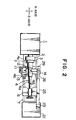
- Fig. 2 is a plan view of the lathe shown in Fig. l;
- Fig. 3 is a c ross-sectional view taken along the line III - III in Fig. l;
- Fig. 4 is a schematic perspective view showing principal portions of Fig. l, with a laser beam forming a quality-changed layer in a surface to be machined of a work;
- Fig. 5 is a schematic perspective view showing chips formed in the machining of the work shown in Fig. 4, by a cutting tool;
- Fig. 6 is a schematic front elevational view showing a second embodiment of the present invention, in which a quality-changed layer extends helically;
- Fig. 7 is a fragmentary schematic perspective view showing a third embodiment of the present invention, in which a nozzle is provided for successively applying cooling fluid to portions of a surface to be machined which has been heated by a laser beam, to cool the surface portions;
- Fig. 8 is a fragmentary schematic cross-sectional view showing a fourth embodiment of the present invention, in which an air jet is used to blow off a cutting oil layer on a surface to be machined of a work;
- Fig. 9 is a fragmentary schematic cross- sectional view showing a fifth embodiment of the present invention, in which a material having the property tending to absorb laser beam is successively deposited on portions of a surface to be machined to which portions the laser beam is to be irradiated;
- Fig. l0 is a cross-sectional view taken along the line X - X in Fig. 9;
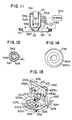
- Fig. ll is a fragmentary schematic cross-sectional view showing a sixth embodiment of the invention, in which an air flow is used to successively preheat portions of a surface to be machined to which portions the laser beam is to be irradiated;
- Fig. l2 is a cross-sectional view taken along the line XII - XII in Fig. ll;
- Fig. l3 is a schematic perspective view showing a seventh embodiment wherein the method according to the present invention is applied to a turning center;
- Fig. l4 is a plan view showing an eighth embodiment of the present invention, in which a quality-changed layer extends spirally;
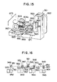
- Fig. l5 is a schematic perspective view showing a ninth embodiment wherein the method according to the present invention is applied to a machining center having a face plate; and
- Fig. l6 is a schematic block diagram showing a tenth embodiment wherein the method according to the present invention is applied to a plurality of cutting apparatuses.
- Embodiments of the present invention will now be described below with reference to the accompanying drawings through which like reference numerals are used to designate like or similar parts or components.
- Referring to Figs. l through 3, a lathe to which a method according to the present invention is applied has a body l on which a
face plate 2 is rotatably supported. Theface plate 2 has achuck 3 for gripping awork 4 such as a rod of a circular cross-section having stepped cylindrical surfaces to be machined 4a, 4b and 4c. Thework 4 is formed of a ferrous metal, aluminum, copper, titanium, ceramic or the like. The center of theend face 4d of thework 4 on the side opposite to thechuck 3 is supported by atail stock 6 which is slidable on aguide surface 7 of the body l. Anapron 8 is slidable on theguide surface 7 in a direction along the axis of thework 4, i.e., along the Z-axis by means of afeed screw 9. A holder ll for supporting a cutting tool l2 is mounted on a table l3 which can incrementally move the cutting tool l2 along the Z-axis. The table l3 is movably mounted on theapron 8 through a base l4 so as to be capable of moving the cutting tool l2 along the Z-axis. - As shown in Fig. l a laser oscillator 2l is located on the floor in side by side relation to the lathe body l. The laser oscillator 2l may be of any one of CO₂ laser, Young laser, Helium-Neon laser, Argon laser, semiconductor laser and the like. The
laser beam 22 from t he laser oscillator 2l is guided by a verticaltubular laser guide 23 secured to a housing of the laser oscillator 2l while being protected by theguide 23, and is reflected by areflecting mirror 24. Thelaser beam 22 from thereflecting mirror 24 is guided by a longitudinally extending, horizontaltubular laser guide 25 and a longitudinally extending, horizontaltubular laser guide 26 telescopically fitted in thetubular guide 25 while being protected by theguides mirror 27. Thetubular laser guide 26 is supported by a vertical supportingpost 28 secured to the base l4. As shown in Fig. 3, thelaser beam 22 reflected by the reflectingmirror 27 is guided and protected by a laterally extending, horizontaltubular guide 29 supported by thepost 28, and is reflected by a reflecting mirror 3l. Thelaser beam 22 from the reflecting mirror 3l is protected and guided by a verticaltubular laser guide 32 telescopically fitted in a vertically downwardly extending,tubular extension 33 of theguide 29 and is condensed by alens 34 to focus onto the surfaces to be machined 4a, 4b and 4c of thework 4, or onto a point e on thesurface 4b, for example, as shown in Figs. l through 3. The point e on thesurface 4b is offset by about 90° in the clockwise direction from a point of contact f of the cutting tool l2 with thesurface 4b as viewed in Fig. 3. - A method of breaking chips according to a first embodiment of the present invention will be described below with reference to Figs. l through 5, particularly to Figs. 4 and 5.
- The
work 4 is first supported by and between thechuck 3 and thetail stock 6 of the lathe. After completion of the rough machining of thecylindrical surfaces work 4, theapron 8 is moved along the Z-axis to locate thelens 34 at an initial position just above theend face 4d of thework 4. Then, the laser oscillator 2l is actuated to generate thelaser beam 22 to allow the same to be irradiated to a point on thecylindrical surface 4a of thework 4 adjacent theend face 4d thereof. Theapron 8 is moved along the Z-axis to the left as viewed in Fig. l, thereby moving thelaser beam 22 relative to thework 4 from theend face 4d toward the other end of thework 4, to successively heat incremental portions of thesurface 4a extending along the axis of thework 4. Since the portions of the surfaces of thework 4 which are heated by thelaser beam 22 are very low in heat capacity, the heated portions are rapidly cooled successively by the adjacent portions of thework 4 and by the ambient air, with a result that a quality-changed layer portion different in composition from the adjacent portions of thework 4, i.e., a quenched and hardenedlayer portion 35a is formed as shown in Fig. 4. The thickness of the quality-changedlayer portion 35a can be suitably determined depending upon the amount of energy of thelaser beam 22 and the feeding rate thereof. - As the
laser beam 22 reaches the step between thesurfaces laser guide 32 is moved relative to theextension 33 to focus thelaser beam 22 onto a point on thesurface 4b. Theapron 8 is then moved along the Z-axis to the left as viewed in Fig. l, to thereby form a quality-changed layer portion 35b in thesurface 4b. In the similar manner, a quality-changedlayer portion 35c is formed on thesurface 4c. Thus, a quality-changedlayer 35 extending in parallel to the axis of thework 4 is formed in the surfaces to be machined of thework 4. - After formation of the quality-changed
layer 35, theapron 8 is returned to the aforesaid initial position, and thework 4 is angularly moved around its axis by a predetermined angle and, then, another quality-changedlayer 36 is formed in thesurfaces layers surfaces - After formation of the required number of quality-changed
layers work 4 is rotated as shown in Fig. 5 and theapron 8 is moved along the Z-axis, to successively finish-machine thesurfaces layers - As will been seen from the foregoing description, the relatively thin chips formed during the finish machining, even though chips are formed of mild steel, for example, are successively broken at the quality-changed
layers - In case the diameter of the
work 4 is small, it will be understood that it is sufficient if only one quality-changedlayer - It is not necessarily required that the quality-changed
layers work 4. For example, as is the case with a second embodiment shown in Fig. 6, a quality-changed layer l35 may extend helically around the axis of thework 4 in thesurfaces work 4 while moving thelaser beam 22 along the Z-axis. What is important is that it is sufficient if the quality-changed layer intersects the path of movement of the cutting tool l2 relative to thework 4. - Fig. 7 shows a third embodiment of the present invention, which includes a nozzle 24l connected to a cutting
oil reservoir 242. The nozzle 24l is fixedly attached to abracket 243. Thebracket 243 is pivotally mounted on abracket 246 secured to theguide 32 by means of screws (not shown) in such a manner that the nozzle 24l is moved together with theguide 32. Immediately after thelaser beam 22 heats successively portions of thesurfaces work 4, the cutting oil from the nozzle 24l is injected onto the heated portions to successively quench those heated portions thereby insuring the formation of the quality-changedlayer 35. The third embodiment having the cooling step shown in Fig. 7 is particularly suitable for use with awork 4 made of a stainless steel. The reason for this is that it is possible to avoid occurrence of intercrystalline corrosion by virtue of the cooling of the heated portions with the cutting oil. - Fig. 8 shows a fourth embodiment of the present invention, which includes an outer tubular member 34l cooperating with a guide 332 corresponding to the
guide 32 shown in Figs. l through 3, to define therebetween anannular passage 342. Thepassage 342 is connected to acompressor 343 and communicates with the inner space of the guide 332 through a plurality oforifices 344 formed in the wall of the guide 332. Theorifices 344 are inclined so as to be directed toward anend opening 345 of the guide 332. The air jet from theend opening 345 successively impinges against the portions of the surfaces, for example, thesurface 4b of thework 4 to be heated by thelaser beam 22, to remove a cuttingliquid layer 346 on the portions to be heated, thereby preventing the diffused reflection of thelaser beam 22 which might otherwise be caused by the cuttingliquid layer 346. Immediately after the removal of the cuttingliquid layer 346 by the air jet, the portions to be heated of the surfaces of the work are successively heated by thelaser beam 22. - Figs. 9 and l0 show a fifth embodiment of the present invention, which utilizes a Young laser oscillator 42l in place of the laser oscillator 2l shown in Figs. l through 3. The
laser beam 22 from the Young laser oscillator 42l is led by an optical fiber bundle 44l so as to focus onto a point on the surfaces, for example,surface 4b of thework 4. The optical fiber bundle 44l is supported by aholder 442 mounted on theapron 8 for movement therewith as shown in Figs. l through 3. Theholder 442 is provided with abore 443 having a circular cross-section and having a bottom wall. Apipe 444 extends through the bottom wall of thebore 443. Thepipe 444 has one end thereof connected to a reservoir 47 containing amixture 446 in which carbon powder is dissolved in a thermosetting resin. The other end opening of the pipe 44 faces toward thesurface 4b of thework 4 at a position immediately upstream of thelaser beam 22 with reference to the direction of movement thereof indicated by the arrow 49l in Fig. 9. Thepipe 444 cooperates with the wall surface of thebore 443 to define therebetween anannular space 453 connected to ablower 448 through apipe 449. A heater element 45l serves to heat air flowing through thepipe 449. - The
mixture 446 of the carbon powder and the thermosetting resin from thereservoir 447 is successively deposited through thepipe 444 onto the portions of thesurface 4b of thework 4 to be heated by thelaser beam 22. The air from theblower 448 is heated by the heater element 45l. The heated air is blown from theannular space 443 against thesurface 4b of thework 4, to harden or cure the thermosetting resin in themixture 446 which is being deposited onto the portions to be heated of thesurface 4b of thework 4. Thelaser beam 22 is irradiated to the depositedblack mixture 446. Because of theblack mixture 446, thelaser beam 22 is efficiently absorbed in the mixture so that the portions to be heated of thesurface 4b are successively heated to form the quality-changedlayer 35 as shown in Fig. 4. - The embodiment shown in Figs. 9 and l0 may utilize black colored ink, or black colored toner used in an electrostatic reproducing machine in substitution for the
mixture 446. What is important is that it is sufficient if a material which has the property tending to absorb the laser beam is deposited onto the portions to be heated of the surfaces of the work prior to the irradiation of thelaser beam 2 to those portions. - Figs. ll and l2 show a sixth embodiment of the present invention, which includes a heating head 54l fixedly secured to the
guide 32 so as to surround the tip thereof to define therebetween anannular space 542. Thespace 542 communicates with ablower 543 through aconduit 544. The head 54l has acylindrical portion 545 in concentric relation to theguide 32 and afrustconical portion 546 projecting downwardly from the lower end of thecylindrical portion 545 to form acentral opening 547 aligned with theguide 32. Aheating element 548 extends in a substantially circular from so as to surround thelaser beam 22 condensed by thelens 34. Theheating element 548 is connected to anelectric power source 549 by a pair of lead wires 55l extending through bores formed in the wall of thefrustconical portion 546. - Air fed from the
blower 543 to thespace 542 through theconduit 544 is heated by theheating element 548. The heated air is blown successively against the portions of the surfaces, for example,surface 4b of thework 4 to be heated by thelaser beam 22, to preheat the portions to be heated to a temperature of 80°C, for example. Thelaser beam 22 is successively irradiated to the preheated portions to form the quality-changedlayer 35 as shown in Fig. 4. Since the portions of thework 4 to be heated by thelaser beam 22 are preheated, these portions to be heated are efficiently heat-treated and are formed into the quality-changed layer. The preheating also makes it possible to remove water soluble cutting oil and the like adhering to the surfaces of thework 4. - Fig. l3 shows a seventh embodiment wherein the method according to the present invention is applied to a turning center. The turning center has a turning
body 650 which comprises a lateral beam 65l supporting acontrol box 652 for controlling a cutting tool 6l2, a pair of vertical slider guides 652a and 652b supporting the beam 65l, a pair ofcolumns columns base body 655 allowing the slide guides 654 to move toward and away from aturntable 656, i.e., in the direction indicated by thearrow 692. - A laser oscillator 62l corresponding to the laser oscillator 2l shown in Figs. l through 3 is fixedly mounted on the lateral beam 65l. A
guide 626 corresponding to theguide 26 shown in Figs. l through 3 is supported by a housing of the laser oscillator 62l retractably in the direction perpendicular to the lateral beam 65l, i.e., in the direction indicated by thearrow 692. Aguide 632 corresponding to theguide 32 shown in Figs. l through 3 is telescopically fitted in theguide 626. The laser beam from the laser oscillator 62l passes through theguides guide 632 and is focused onto a point on theannular surface 604a of thework 604 to be machined on theturntable 656. - After completion of the rough machining of the
surface 604a of thework 604, the laser beam is irradiated to thework 604 on theturntable 656. The cooperation of the rotation of thework 604 by theturntable 656 with the linear movement of the guide 62l as indicated by thearrow 692, allows a plurality of radially extending, quality-changedlayers surface 604a, similar to the quality-changedlayer 35 described in connection with Fig. 4. After formation of the radial quality-changedlayers surface 604a to be machined is finish-machined by means of a finishing cutting tool 6l2. Chips formed during the finish machining are broken at the quality-changedlayers - Although the seventh embodiment shown in Fig. l3 has been described as having the quality-changed
layers layer 735 may extend in a spiral form on thesurface 604a to be machined of thework 604 as is the case with an eighth embodiment shown in Fig. l4. What is important is that it is sufficient if the quality-changed layer extends in intersecting relationship to the path of movement of the cutting tool 6l2 with respect to thework 604. - It should be understood that each of the embodiments shown in Figs. 7 through l2 can be applied to the seventh embodiment shown in Fig. l3.
- Fig. l5 shows a ninth embodiment wherein the method according to the present invention is applied to a machining center having a face plate. The machining center comprises a body 86l and an automatic
tool interchanging device 862. Therotary face plate 863 is supported by a base 864 slidable along acolumn 865 of the body 86l in the direction indicated by the arrow 89l. A cutting tool 8l2 is supported by a holder 8ll mounted on therotary face plate 863. A table 867 having mounted thereon awork 804 having an annular surface to be machined 804a is supported by abase 868 for rotation and for reciprocating motion in the direction indicated by thearrow 892. Thebase 868 is supported by the base body 87l for movement indicated by thearrow 893. - A laser oscillator 82l similar to the laser oscillator 2l shown in Figs. l through 3 is fixedly secured to the
base 864. A guide 832 corresponding to theguide 32 shown in Figs. l through 3 is supported by a housing of the laser oscillator 82l so as to be retractable in the direction indicated by thearrow 893. A lens (not shown) similar to thelens 34 shown in Figs. l through 3 is incorporated in the guide 832. The laser beam 822 from the laser oscillator 82l passes through the guide 832 and the lens incorporated therein to focus on a point on thesurface 804a of thework 804. In order to absorb the laser beam reflected from thework 804 or the laser beam which does not impinge against thework 804, the machining center is preferably surrounded by a well-known laser-beam absorbing plate 873. It is of course possible to arrange the laser-beam absorbing plate 873 around the lathe shown in Figs. l through 3 and the turning center shown in Fig. l3. - After completion of the rough machining of the
surface 804a of thework 804, the laser beam 822 is irradiated to thesurface 804a during a period within which the automatictool interchanging device 862 is changing the rough machining tool to a finish machining tool 8l2, to form a plurality of circumferentially spaced, radially extending quality-changed layers 835a, 835b ... similar to the quality-changedlayer 35 described in connection with Fig. 4. After the formation of the quality-changed layers 835a, 835b ..., thesurface 804a is machined by the finish machining tool 8l2. The chips formed during the finish machining are broken at the quality-changed layers 835a, 835b ... thereby effectively preventing the chips from twining themselves around the cutting tool 8l2. - Although the ninth embodiment shown in Fig. l5 has been described as having the quality-changed layers 835a, 835b ... extending radially, a quality-changed layer in the form of spiral as is the case with the eighth embodiment of Fig. l4 may be formed in the
surface 804a of thework 804. - It should be understood that it is possible to apply either one of the embodiments shown in Figs. 7 through l2 to the ninth embodiment shown in Fig. l5.
- Fig. l6 shows a chip breaker system according to a tenth embodiment of the present invention wherein a laser beam from a single laser oscillator is irradiated to a work supported by at least one of a plurality of cutting apparatuses. The system comprises a single laser oscillator 92l similar to that 2l shown in Figs. l through 3, and a plurality of (four in the illustrated embodiment) cutting
apparatuses apparatus mirrors 95l and 954 are fixedly mounted within the laser guides 946 and 949, respectively. Half-mirrors mirrors 957 and 958 placed one upon the other and oriented at an angle of 90° to each other are vertically movably arranged within acommon laser guide 956. When the refecting mirror 957 is positioned in the laser path from the laser oscillator 92l, the reflecting mirror 957 reflects thelaser beam 922 from the laser oscillator 92l toward themirrors 952 and 95l. When the reflectingmirror 958 is positioned in the laser path from the laser oscillator 92l, the reflectingmirror 958 reflects thelaser beam 922 from the laser oscillator 92l toward themirrors cutting apparatus 942, for movement between a position where the mirror 96l is in the laser path from the reflecting mirror 95l to totally reflect the laser beam from the reflecting mirror 95l and a position where the mirror 96l i s out of the laser path from the reflecting mirror 95l to allow thelaser beam 922 from the reflecting mirror 95l to be irradiated to the work mounted on thecutting apparatus 942. Similarly, total reflection mirrors 962, 963 and 964 are respectively arranged between the half-mirror 952 and thecutting apparatus 943, between the half-mirror 953 and thecutting apparatus 944, and between thetotal reflection mirror 954 and thecutting apparatus 945. When it is desired to irradiate the laser beam to the work mounted on thecutting apparatus 942, the pair of reflectingmirrors 957 and 958 within thecommon laser guide 956 are vertically moved to locate the reflecting mirror 957 in the laser path from the laser oscillator 92l. The total mirror 96l is moved to the position out of the laser path from the reflecting mirror 95l, and the remaining total reflection mirrors 962, 963 and 964 are moved in the laser paths from the respective reflectingmirrors laser beam 922 from the laser oscillator 92l is reflected by the total reflection mirror 957 and is directed to the half-mirror 952 and the reflecting mirror 95l. A portion of thelaser beam 922 from the total reflection mirror 957 is directed to the reflecting mirror 95l through the half-mirror 952, and the remaining laser beam is directed to thetotal reflection mirror 962 and is totally reflected thereby. Thelaser beam 922 directed to the reflecting mirror 95l is reflected thereby and is irradiated to the work mounted on thecutting apparatus 942, so that at least one quality-changed layer is formed in the surface to be machined of the work in the manner as described with reference to Fig. 4. - As will be seen from the foregoing description, the
laser beam 922 can be directed to the cuttingapparatuses 942 and/or 943, or 944 and/or 945 by appropriately operating the reflectingmirrors 957 and 958 and the total reflection mirrors 96l to 964. - The tenth embodiment shown in Fig. l6 can carry out the treatment of the chips in the plurality of cutting
apparatuses 942 to 945 by the single laser oscillator 92l, and is particularly suitable for use in the Flexible Manufacturing System or the Factory Automation. - Although the first to tenth embodiments of the present invention illustrated in the accompanying drawings have been described as utilizing the laser beam, it will be appreciated by one skilled in the art that an electron beam can be substituted for the laser beam. It should also be understood that the combination of the Young laser oscillator and the optical fiber bundle in the fifth embodiment shown in Fig. 9 can be substituted for the combination of the laser oscillator and the laser guides shown in the first to fourth embodiments and in the sixth to tenth embodiments.
- As described above, according to the present invention, since the thin chips formed during the machining of a work, in particular, during the final finish machining of a work, can automatically be broken, it is positively prevented that the chips twine themselves around the cutting tool or jigs. Therefore, it is made possible to enhance the efficiency of machining while an unattened operation of a factory is achieved, and the Flexible Manufacturing System and the Factory Automation can be realized in the machining of not only cast products but also works made of mild steel, alloy steels or the like. The formation of the quality-changed layer or layers by means of the beam in accordance with the present invention may, of course, be done prior to the rough machining of the work depending upon the material of the work to break the chips formed during the rough machining. Additionally, it is preferable that the formation of at least one quality-changed layer by the beam is effected automatically during the period within which the rough machining tool is changed to a finish machining tool. In this case, the loss of machine operation time can be made to the minimum, while the condition of the i rradiation of the beam can be periodically inspected.
Claims (14)
preparing a work having a surface to be machined;
irradiating a beam to the work to heat a portion of said surface, to thereby form in said surface a quality-changed layer different in composition from the adjacent portions of said surface; and
machining said surface by a cutting tool to permit chips formed by the machining to be broken at said quality-changed layer.
moving said beam so as to cross a path of movement of the cutting tool relative to said surface, to form at least one elongated quality-changed layer in said surface.
moving said beam so as to cross a path of movement of the cutting tool relative to said surface, to form a plurality of spaced, elongated quality-changed layers in said surface.
after the heating of the portion of said surface by said beam, applying a cooling medium to the heated portion to quench and harden said heated portion, to thereby form said quality-changed layer.
applying an air jet to the portion to be heated of said surface, to clean said portion to be heated.
prior to the irradiation of said beam, depositing a material onto the portion to be heated of said surface, said material having a property tending to absorb said beam.
depositing a mixture in which carbon powder is dissolved in a thermosetting resin, onto said portion to be heated of said surface; and drying said mixture by hot gas flow.
Applications Claiming Priority (2)
| Application Number | Priority Date | Filing Date | Title |
|---|---|---|---|
| JP189645/85 | 1985-08-30 | ||
| JP18964585 | 1985-08-30 |
Publications (2)
| Publication Number | Publication Date |
|---|---|
| EP0220421A2 true EP0220421A2 (en) | 1987-05-06 |
| EP0220421A3 EP0220421A3 (en) | 1988-04-06 |
Family
ID=16244777
Family Applications (1)
| Application Number | Title | Priority Date | Filing Date |
|---|---|---|---|
| EP86111909A Withdrawn EP0220421A3 (en) | 1985-08-30 | 1986-08-28 | Chip breaking method |
Country Status (3)
| Country | Link |
|---|---|
| EP (1) | EP0220421A3 (en) |
| JP (1) | JPS62152601A (en) |
| KR (1) | KR870001895A (en) |
Cited By (5)
| Publication number | Priority date | Publication date | Assignee | Title |
|---|---|---|---|---|
| WO2007028359A1 (en) * | 2005-09-09 | 2007-03-15 | Fraunhofer-Gesellschaft Zür Förderung Der Angewandten Forschung E.V. | Method and device for machining workpieces made of glass or glass ceramics |
| RU2641444C2 (en) * | 2016-06-29 | 2018-01-17 | федеральное государственное бюджетное образовательное учреждение высшего образования "Санкт-Петербургский горный университет" | Method of mechanical processing of steel casting with fragmentation of chips |
| RU2699469C1 (en) * | 2019-04-22 | 2019-09-05 | федеральное государственное бюджетное образовательное учреждение высшего образования "Санкт-Петербургский горный университет" | Steel billet machining method with chips crushing |
| CN111390204A (en) * | 2020-04-20 | 2020-07-10 | 南京嘉玺数控科技有限公司 | Active chip breaking method for continuous turning |
| RU2764449C1 (en) * | 2021-07-19 | 2022-01-17 | федеральное государственное бюджетное образовательное учреждение высшего образования «Санкт-Петербургский горный университет» | Method for mechanical processing of a steel workpiece with chip crushing |
Families Citing this family (2)
| Publication number | Priority date | Publication date | Assignee | Title |
|---|---|---|---|---|
| DE19613183C1 (en) * | 1996-04-02 | 1997-07-10 | Daimler Benz Ag | Hard steel workpiece precision machining method |
| JP5109491B2 (en) * | 2007-06-15 | 2012-12-26 | アイシン・エィ・ダブリュ株式会社 | Turning method and workpiece used for turning |
Citations (5)
| Publication number | Priority date | Publication date | Assignee | Title |
|---|---|---|---|---|
| DE2804072A1 (en) * | 1977-01-31 | 1978-08-03 | Nippon Kogaku Kk | DEVICE FOR THE UNIFORM GUIDANCE OF A CHIP CREATED DURING TURNING |
| US4356376A (en) * | 1981-05-13 | 1982-10-26 | General Electric Company | Pulse laser pretreated machining |
| JPS58196901A (en) * | 1982-05-13 | 1983-11-16 | Mitsubishi Heavy Ind Ltd | Cuttng and machining process |
| EP0104971A2 (en) * | 1982-08-30 | 1984-04-04 | Bendix Automation Company | Machine tool with laser heat treating |
| JPS5985393A (en) * | 1982-11-08 | 1984-05-17 | Hitachi Ltd | Cutting device under heating |
-
1986
- 1986-08-27 JP JP61198865A patent/JPS62152601A/en active Pending
- 1986-08-28 EP EP86111909A patent/EP0220421A3/en not_active Withdrawn
- 1986-08-29 KR KR1019860007185A patent/KR870001895A/en not_active Application Discontinuation
Patent Citations (5)
| Publication number | Priority date | Publication date | Assignee | Title |
|---|---|---|---|---|
| DE2804072A1 (en) * | 1977-01-31 | 1978-08-03 | Nippon Kogaku Kk | DEVICE FOR THE UNIFORM GUIDANCE OF A CHIP CREATED DURING TURNING |
| US4356376A (en) * | 1981-05-13 | 1982-10-26 | General Electric Company | Pulse laser pretreated machining |
| JPS58196901A (en) * | 1982-05-13 | 1983-11-16 | Mitsubishi Heavy Ind Ltd | Cuttng and machining process |
| EP0104971A2 (en) * | 1982-08-30 | 1984-04-04 | Bendix Automation Company | Machine tool with laser heat treating |
| JPS5985393A (en) * | 1982-11-08 | 1984-05-17 | Hitachi Ltd | Cutting device under heating |
Non-Patent Citations (2)
| Title |
|---|
| PATENT ABSTRACTS OF JAPAN, vol. 8, no. 195 (M-323)[1632], 7th September 1984; & JP - A - 59 085393 (HITACHI SEISAKUSHO) 17-05-1984 * |
| PATENT ABSTRACTS OF JAPAN, vol. 8, no. 40 (M-278)[1477], 21nd February 1984; & JP - A - 58 196 901 (MITSUBISHI JUKOGYO) 16-11-1983 * |
Cited By (5)
| Publication number | Priority date | Publication date | Assignee | Title |
|---|---|---|---|---|
| WO2007028359A1 (en) * | 2005-09-09 | 2007-03-15 | Fraunhofer-Gesellschaft Zür Förderung Der Angewandten Forschung E.V. | Method and device for machining workpieces made of glass or glass ceramics |
| RU2641444C2 (en) * | 2016-06-29 | 2018-01-17 | федеральное государственное бюджетное образовательное учреждение высшего образования "Санкт-Петербургский горный университет" | Method of mechanical processing of steel casting with fragmentation of chips |
| RU2699469C1 (en) * | 2019-04-22 | 2019-09-05 | федеральное государственное бюджетное образовательное учреждение высшего образования "Санкт-Петербургский горный университет" | Steel billet machining method with chips crushing |
| CN111390204A (en) * | 2020-04-20 | 2020-07-10 | 南京嘉玺数控科技有限公司 | Active chip breaking method for continuous turning |
| RU2764449C1 (en) * | 2021-07-19 | 2022-01-17 | федеральное государственное бюджетное образовательное учреждение высшего образования «Санкт-Петербургский горный университет» | Method for mechanical processing of a steel workpiece with chip crushing |
Also Published As
| Publication number | Publication date |
|---|---|
| JPS62152601A (en) | 1987-07-07 |
| EP0220421A3 (en) | 1988-04-06 |
| KR870001895A (en) | 1987-03-28 |
Similar Documents
| Publication | Publication Date | Title |
|---|---|---|
| EP1733837B1 (en) | Apparatus for separating a flat workpiece made of a brittle material by means of a laser | |
| US5859405A (en) | Cutting tool precision turning method and apparatus for a heat-treatable steel workpiece | |
| Rajagopal et al. | Machining aerospace alloys with the aid of a 15 kW laser | |
| CA1202373A (en) | Machine tool with laser heat treating | |
| JP3247878B2 (en) | Laser processing method and apparatus for metal hollow body surface | |
| US4356376A (en) | Pulse laser pretreated machining | |
| DE2940127A1 (en) | METHOD AND DEVICE FOR HEAT TREATMENT | |
| US4229640A (en) | Working pieces by laser beam | |
| EP3437788B1 (en) | Laser machining apparatus and laser machining method | |
| EP0707920A2 (en) | Compact laser processing head for laser processing of material, with an integrated on-line track control | |
| EP0220421A2 (en) | Chip breaking method | |
| US4625093A (en) | Stock removal by laser cutting | |
| CN115379918A (en) | Device and method for producing and reprocessing a layer applied by laser cladding | |
| JPH05115993A (en) | Laser beam machine | |
| JP2003525351A (en) | Method for producing a cylindrical, partial cylindrical or hollow cylindrical component with an alloyed surface and apparatus for carrying out the method | |
| JPS5869745A (en) | Glass work cutting system utilizing laser supplementarily | |
| EP0369057B1 (en) | Method and device for treating machined surface of workpiece | |
| JPH03501364A (en) | A method for micromachining the surface of a workpiece using a laser beam | |
| Bass et al. | Laser assisted machining | |
| EP0535620A1 (en) | Method for patterning and polishing glass workpieces, in particular made of lead crystal | |
| DE102020106822B4 (en) | Device and method for reworking layers applied by laser deposition welding | |
| SU1743770A1 (en) | Method of laser alloying and surfacing | |
| Copley¹ et al. | Shaping silicon compound ceramics with a continuous wave carbon dioxide laser | |
| US4786777A (en) | Process and apparatus for wire electrode trimming using a laser | |
| DE102009051336B4 (en) | Use of brilliant laser radiation from a fiber or disc laser for welding workpieces made of ceramic, dental ceramic, porcelain, hard metal or high-alloyed austenitic steels |
Legal Events
| Date | Code | Title | Description |
|---|---|---|---|
| PUAI | Public reference made under article 153(3) epc to a published international application that has entered the european phase |
Free format text: ORIGINAL CODE: 0009012 |
|
| AK | Designated contracting states |
Kind code of ref document: A2 Designated state(s): CH DE GB LI |
|
| PUAL | Search report despatched |
Free format text: ORIGINAL CODE: 0009013 |
|
| AK | Designated contracting states |
Kind code of ref document: A3 Designated state(s): CH DE GB LI |
|
| 17P | Request for examination filed |
Effective date: 19880926 |
|
| 17Q | First examination report despatched |
Effective date: 19891214 |
|
| STAA | Information on the status of an ep patent application or granted ep patent |
Free format text: STATUS: THE APPLICATION IS DEEMED TO BE WITHDRAWN |
|
| 18D | Application deemed to be withdrawn |
Effective date: 19900425 |
|
| RIN1 | Information on inventor provided before grant (corrected) |
Inventor name: MIURA, YOSHIO Inventor name: SAITO, HIROSHI Inventor name: OTA, KATURO |