EP0220258B1 - Vaporizers and wick assemblies therefor - Google Patents
Vaporizers and wick assemblies therefor Download PDFInfo
- Publication number
- EP0220258B1 EP0220258B1 EP86902857A EP86902857A EP0220258B1 EP 0220258 B1 EP0220258 B1 EP 0220258B1 EP 86902857 A EP86902857 A EP 86902857A EP 86902857 A EP86902857 A EP 86902857A EP 0220258 B1 EP0220258 B1 EP 0220258B1
- Authority
- EP
- European Patent Office
- Prior art keywords
- assembly
- wick
- backing sheet
- wick material
- vaporizer
- Prior art date
- Legal status (The legal status is an assumption and is not a legal conclusion. Google has not performed a legal analysis and makes no representation as to the accuracy of the status listed.)
- Expired - Lifetime
Links
- 230000000712 assembly Effects 0.000 title description 3
- 238000000429 assembly Methods 0.000 title description 3
- 239000000463 material Substances 0.000 claims abstract description 67
- 230000002745 absorbent Effects 0.000 claims abstract description 8
- 239000002250 absorbent Substances 0.000 claims abstract description 8
- 239000004744 fabric Substances 0.000 claims abstract description 7
- 239000006200 vaporizer Substances 0.000 claims description 38
- 239000007788 liquid Substances 0.000 claims description 22
- 238000005096 rolling process Methods 0.000 claims description 11
- 229920006395 saturated elastomer Polymers 0.000 claims description 8
- 230000013011 mating Effects 0.000 claims description 5
- 238000004519 manufacturing process Methods 0.000 claims description 4
- 230000003444 anaesthetic effect Effects 0.000 abstract description 20
- 229910001220 stainless steel Inorganic materials 0.000 abstract description 5
- 239000010935 stainless steel Substances 0.000 abstract description 5
- 230000008016 vaporization Effects 0.000 description 23
- 239000012159 carrier gas Substances 0.000 description 16
- 239000007789 gas Substances 0.000 description 13
- 229940124326 anaesthetic agent Drugs 0.000 description 9
- 239000003193 general anesthetic agent Substances 0.000 description 9
- 239000002184 metal Substances 0.000 description 4
- 230000006835 compression Effects 0.000 description 3
- 238000007906 compression Methods 0.000 description 3
- 238000000034 method Methods 0.000 description 2
- 230000002035 prolonged effect Effects 0.000 description 2
- 238000007789 sealing Methods 0.000 description 2
- 239000007787 solid Substances 0.000 description 2
- 238000003466 welding Methods 0.000 description 2
- 229910000906 Bronze Inorganic materials 0.000 description 1
- 229910000792 Monel Inorganic materials 0.000 description 1
- OAICVXFJPJFONN-UHFFFAOYSA-N Phosphorus Chemical compound [P] OAICVXFJPJFONN-UHFFFAOYSA-N 0.000 description 1
- QVGXLLKOCUKJST-UHFFFAOYSA-N atomic oxygen Chemical compound [O] QVGXLLKOCUKJST-UHFFFAOYSA-N 0.000 description 1
- 230000015572 biosynthetic process Effects 0.000 description 1
- 239000010974 bronze Substances 0.000 description 1
- 239000004020 conductor Substances 0.000 description 1
- 238000001816 cooling Methods 0.000 description 1
- KUNSUQLRTQLHQQ-UHFFFAOYSA-N copper tin Chemical compound [Cu].[Sn] KUNSUQLRTQLHQQ-UHFFFAOYSA-N 0.000 description 1
- 230000000881 depressing effect Effects 0.000 description 1
- 230000000694 effects Effects 0.000 description 1
- 238000001704 evaporation Methods 0.000 description 1
- 230000008020 evaporation Effects 0.000 description 1
- 239000000945 filler Substances 0.000 description 1
- 239000000203 mixture Substances 0.000 description 1
- 239000001301 oxygen Substances 0.000 description 1
- 229910052760 oxygen Inorganic materials 0.000 description 1
- 230000002093 peripheral effect Effects 0.000 description 1
- 238000003825 pressing Methods 0.000 description 1
- 238000004080 punching Methods 0.000 description 1
- 230000029058 respiratory gaseous exchange Effects 0.000 description 1
- 238000011144 upstream manufacturing Methods 0.000 description 1
- 238000009834 vaporization Methods 0.000 description 1
Images
Classifications
-
- A—HUMAN NECESSITIES
- A61—MEDICAL OR VETERINARY SCIENCE; HYGIENE
- A61M—DEVICES FOR INTRODUCING MEDIA INTO, OR ONTO, THE BODY; DEVICES FOR TRANSDUCING BODY MEDIA OR FOR TAKING MEDIA FROM THE BODY; DEVICES FOR PRODUCING OR ENDING SLEEP OR STUPOR
- A61M16/00—Devices for influencing the respiratory system of patients by gas treatment, e.g. ventilators; Tracheal tubes
- A61M16/10—Preparation of respiratory gases or vapours
- A61M16/14—Preparation of respiratory gases or vapours by mixing different fluids, one of them being in a liquid phase
- A61M16/18—Vaporising devices for anaesthetic preparations
-
- Y—GENERAL TAGGING OF NEW TECHNOLOGICAL DEVELOPMENTS; GENERAL TAGGING OF CROSS-SECTIONAL TECHNOLOGIES SPANNING OVER SEVERAL SECTIONS OF THE IPC; TECHNICAL SUBJECTS COVERED BY FORMER USPC CROSS-REFERENCE ART COLLECTIONS [XRACs] AND DIGESTS
- Y10—TECHNICAL SUBJECTS COVERED BY FORMER USPC
- Y10S—TECHNICAL SUBJECTS COVERED BY FORMER USPC CROSS-REFERENCE ART COLLECTIONS [XRACs] AND DIGESTS
- Y10S261/00—Gas and liquid contact apparatus
- Y10S261/65—Vaporizers
-
- Y—GENERAL TAGGING OF NEW TECHNOLOGICAL DEVELOPMENTS; GENERAL TAGGING OF CROSS-SECTIONAL TECHNOLOGIES SPANNING OVER SEVERAL SECTIONS OF THE IPC; TECHNICAL SUBJECTS COVERED BY FORMER USPC CROSS-REFERENCE ART COLLECTIONS [XRACs] AND DIGESTS
- Y10—TECHNICAL SUBJECTS COVERED BY FORMER USPC
- Y10T—TECHNICAL SUBJECTS COVERED BY FORMER US CLASSIFICATION
- Y10T29/00—Metal working
- Y10T29/49—Method of mechanical manufacture
- Y10T29/49826—Assembling or joining
- Y10T29/49861—Sizing mating parts during final positional association
Definitions
- This invention relates to vaporizers, in particular anaesthetic vaporizers, and to wick assemblies therefor.
- wick assembly for use in anaesthetic vaporizers.
- One type of known vaporizer includes a vaporizing chamber partly filled with liquid anaesthetic in which a lower portion of the wick assembly is immersed.
- a carrier gas stream flows over the vaporizing surface of the wick to entrain anaesthetic vapour and the mixture is then delivered to the patient.
- the gas In order that the gas should become sufficiently saturated with anaesthetic vapour it must remain in contact with the vaporizing surface of the wick for a long period, and this has been achieved by guiding the gas downwards via a helical path formed in an annular chamber defined by the space between two concentric cylinders of wick material.
- the wick assembly comprises a number of vertical, spaced apart sheets of wick material which are partly immersed in liquid anaesthetic, in which the gas flows past each such sheet via a multiplicity of horizontal passages.
- a wick assembly comprising a plate fastened in a spirally wound condition and acting as a backing sheet to a spirally wound coil of absorbent paper so as to define a spiral flow passage extending through the assembly.
- the coil of paper is inserted axially into the spiral plate along the innermost surface thereof, whereby the natural tendency of the paper to unwind enables it to be held to the spiral plate by means of simple fixtures at the ends.
- wick material known for example from British Patent No. 1043110, is metallic wire cloth.
- the capillary action of such cloth can be greatly enhanced by securing it in contact with a smooth unperforated metal surface, due to the formation of additional small upwardly directed passages between the wires of the mesh and the surface of the metal plate.
- the invention provides a wick assembly for a vaporizer, such assembly comprising an absorbent wick material provided with a substantially impermeable backing sheet, the wick material and the backing sheet being arranged in a substantially spiral configuration so as to define a substantially spiral flow passage extending through the assembly, fastening means to hold said wick material and backing sheet in such spiral configuration, and means for detachably mounting the assembly in a vaporizer, characterised in that the spiral configuration is formed by mating together the wick material and backing sheet in face to face relationship and rolling them into the spiral configuration with the wick material disposed on the outwardly facing convex side of the backing sheet, so that in the rolled assembly the wick material is stretched into intimate contact with the backing sheet.
- the wick material is stretched as the assembly is rolled into a spiral, thereby assisting good capillary action and good thermal contact with the backing sheet, so that a desired degree of vapour saturation may be achieved with a relatively simple wick structure.
- the wick assembly will be rolled into the spiral configuration in such a manner that its outside shape is generally cylindrical i.e. having a circular outer cross-section which exhibits internally the spiral configuration.
- the precise configuration of the spiral can vary such that the cross-section of the cylinder can be any convenient shape. For example it may be oval or elliptical.
- one longitudinal end of the wick assembly is immersed in a liquid which is drawn up through the wick material by capillary action, such action being assisted by the presence of the backing sheet which provides additional upward passages defined between the absorbent material and the backing sheet.
- the drawing up may take place along substantially the whole length of the spiral.
- a stream of carrier gas is then passed from one end of the spiral to the other, either from the outside thereof to the centre or vice versa, via the spiral flow passage and the carrier becomes saturated with vapour due to its prolonged contact with the wick material carrying the liquid.
- the wick assembly is particularly suitable for use in an anaesthetic vaporizer, in which case the liquid is a suitable anaesthetic agent.
- the assembly is a self-contained unit it may be mounted in a vaporizer in an interchangeable manner, and the wick assembly may thus be readily replaced and/or removed for servicing as necessary and this represents a significant practical advantage.
- the wick material may comprise a plurality of sheets spaced at intervals or adjacent to each other along the length of the spiral. Preferably, however, the wick material comprises a single continuous sheet.
- the wick material and the backing sheet may be of any suitable configuration to suit vaporizing requirements, in one preferred arrangement the wick assembly is fabricated from a strip of wick material and impermeable backing sheet whose length is substantially longer than its width, for example a length twenty times longer than the width. This results in a spiral flow passage which is twenty times longer than the height of the wick assembly, so that in use a high degree of saturation of the carrier gas with vapour is obtained, while at the same time the wick assembly as a whole is particularly compact and easy to handle and install.
- the wick material should be selected to ensure that e.g. an anaesthetic agent to be evaporated is spread in a thin liquid film over a large vaporizing surface of the wick assembly. It should therefore have a good capillary action in order to provide a liquid film extending a substantial distance above the surface of the liquid and it should also have good heat conductivity so as to transfer heat from the environment to offset the cooling effect of evaporation.
- the material should be inert to the liquid intended to be vaporized, and one suitable material is fine metallic wire cloth, made for example of stainless steel, Monel (registered trade mark) metal or phosphor bronze.
- wick material in sheet form and the backing sheet are secured to each other generally uniformly over the whole of their mating faces.
- the impermeable backing sheet may for example be secured to the wick material by spot welding.
- the backing material should be inert to the liquid concerned and is preferably a good heat conductor; stainless steel is thus particularly suitable.
- the spiral flow passage defined on each side by opposed portions of the backing sheet, in which the wick material is disposed, should neither be so narrow that there is an undesirable resistance to flow of carrier gas, nor should it be so wide that a proportion of the gas can flow along the passage without being in good contact with the wick material.
- suitable spacing means can be provided, and to this end, for example, spacing inserts arranged at intervals along the passage.
- the backing sheet is dimpled at intervals to form projections so that the spacing of opposed portions of the backing sheet is at least the height of such projections.
- the projections protrude from the backing sheet through spaces in the wick material, but in a preferred arrangement the wick material is in contact with the face of the backing sheet on which the dimples are re-entrant.
- the spiral configuration can then be arranged so that the projections protrude from the backing sheet across the spiral passage to just touch the opposed wick material, and if the projections are all of the same size then the spiral passage will have a uniform width.
- wick material and the backing sheet are rolled into the spiral configuration during fabrication, there may then be a tendency for the assembly to unroll itself. It is thus necessary to provide the fastening means to prevent such unrolling; such means may comprise for example welds, one or more clips, or rivets at the outer end of the spiral, but in a particularly effective arrangement a retaining band or clip extends round the outside of the assembly to retain the spiral configuration. Such retaining means is desirable even if there is no tendency to unroll, to improve generally the ease of handling of the assembly in the form of a self-contained unit.
- the wick assembly can be readily serviced or replaced in e.g. an anaesthetic vaporizer, it should include suitable mounting means.
- the mounting means includes a clamping member arranged perpendicularly to the longitudinal axis of the wick assembly and abutting one longitudinal end thereof, and one or more fixing element extending through the assembly from said member to the other longitudinal end thereof, such fixing element(s) being adapted detachably to mount the assembly to a vaporizer e.g. by being screw threaded.
- the clamping member can be of any suitable shape to serve as an abutment against one spiral edge of the wick material and backing sheet.
- a first closure plate substantially covers one end of the assembly and includes a central aperture e.g. for the entry of liquid to be vaporized, a second closure plate being provided substantially covering the other end of the assembly and having an aperture e.g. for the exit of vapour saturated carrier gas, and said fixing element comprising at least one fixing bolt connecting said first and second closure plates.
- the invention provides a method of manufacturing a wick assembly for a vaporizer, comprising providing a layer of absorbent wick material, providing a substantially impermeable backing sheet, arranging the wick material and backing sheet in a substantially spiral configuration so as to define a substantially spiral flow passage extending through the assembly, fastening the wick material and backing sheet in said spiral configuration, and providing means for detachably mounting the assembly in a vaporizer, characterised in that the spiral configuration is formed by mating together the wick material and backing sheet in face to face relationship and rolling them into the spiral configuration with the wick material disposed on the outwardly facing convex side of the backing sheet, so that in the rolled assembly the wick material is stretched into intimate contact with the backing sheet.
- the rolling will generally be accomplished by gripping one end of the backing sheet which is to form the centre of the spiral and rotating this end, either manually or mechanically.
- the backing sheet is provided at one end with a drive tag bent away from the layer of wick material, and this drive tag is gripped and rotated to roll up the assembly, for example by using a rolling tool having a slot for receiving the drive tag.
- One or more such drive tags may be provided along said end of the backing sheet, but preferably a single tag extends along substantially the whole of the end to ensure uniformity in the rolling action.
- the or each tag is removed after rolling, for example, by means of a hand saw.
- the fastening of the assembly in a spiral configuration may be achieved by means of, e.g., welding or a suitable band or clip as discussed above.
- the invention provides a vaporizer including a detachable wick assembly as discussed above.
- a vaporizer In such a vaporizer an advantageously prolonged contact between the carrier gas and the wick material disposed on the outwardly facing convex side of the backing sheet can be achieved by means of the spiral passage, thereby ensuring that the carrier becomes saturated with e.g. anaesthetic vapour.
- the vaporizer can be a plenum vaporizer operating under a positive carrier gas pressure generally supplied from a cylinder, or it can be a draw-over type inhaler operated by the breathing of a patient which draws air or oxygen enriched air through the vaporizer.
- the vaporizer will include a vaporizing chamber adapted to receive e.g. liquid anaesthetic agent and in which the wick assembly is disposed.
- the vaporizer preferably includes inlet means for the entry of carrier gas to said vaporizing chamber, and outlet means for the exit of saturated carrier gas from the chamber, wherein the gas flows in use between the inlet and outlet means via the spiral passage.
- the wick assembly is arranged for the gas to enter the spiral passage at the outside thereof and to flow to the centre thereof, the wick assembly being mounted to a wall of the vaporizing chamber in sealing engagement therewith to permit gas flow from the wick assembly centre out of the vaporizing chamber.
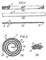
- the wick assembly 1 shown in Figure 3 is manufactured as follows. Referring to Figure 1(a), a straight strip 2 is cut from a sheet of suitable wick material.
- Figure 1(b) shows a backing strip 3 cut from a solid sheet of stainless steel to a length slightly longer than the wick material strip 2. Typical dimensions of the two strips are a length of about 1000mm and a width of about 50mm.
- the backing strip is dimpled by punching to form two parallel rows of projections adjacent each straight edge of the strip, the projections being spaced at about 30mm intervals and projecting outwardly by about 2mm.
- the wick material strip 2 is then spot-welded to the backing strip 3 on its face without projections as shown in Figure 1(c) and the longer end of the backing strip is bent away from the wick material to form a drive tag 5.
- the drive tag is gripped and rotated thereby rolling the pair of strips into a spiral configuration 6 having an overall cylindrical shape with the drive tag at the centre, as shown in Figure 2(a).
- the spiral is formed with the wick material on the outside of the backing strip so that the wick material is stretched by the rolling process and remains in pre-stressed contact with the solid backing strip, assisting capillary action.
- the spiral is tightened until the inwardly protruding projections 4 extend across the spiral passage 7 to just touch the wick material strip 2, as shown in Figure 2(c), thereby ensuring that the passage 7 is of uniform width throughout its length.
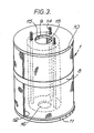
- a retaining band 8 is fitted round the periphery thereof, and the drive tag 5 is then removed by means of a hand saw to provide an axial cavity 9 in the centre of the spiral.
- Two end closure plates 10 and 11 are sealed to the top and bottom respectively of the spiral so that the spiral passage 7 defined between adjacent portions of the backing strip extends about 1000mm from an outside rectangular opening 12 to an inner rectangular opening 13 in the centre of the spiral.
- the closure plates are held in position by three fixing bolts 14 which extend from the bottom plate 11 through the assembly to the top plate 10 from which they project upwardly. Suitable apertures are provided in the closure plates to receive the fixing bolts, while top plate 10 includes an opening 15 for the passage of carrier gas and the bottom plate 11 includes an opening 16 for the entry and drainage of liquid anaesthetic agent.
- the projecting fixing bolts 14 are used to secure the wick assembly to an anaesthetic vaporizer. It will be seen that the wick assembly forms a self-contained unit which may readily be secured within a vapouriser by means of the bolts 14, enabling easy removal of the assembly for servicing and/or replacement when required.
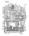
- the anaesthetic vaporizer 17 shown in Figure 4 is a plemunm vaporizer comprising a body 18 within which is a vaporizing chamber 19, a head 20 mounted on the body and housing the control structure of the vaporizer, a wick assembly 1 suspended from the head 20, and a liquid level indicator and fiiler unit 21.
- the body 18 which is of stainless steel is cylindrical in shape and is closed at its lower end by a sealing member 22.
- the liquid level indicator and filler unit 21 communicates with the vaporizing chamber 19 at two points 23 and 24 to permit filling of the chamber with liquid anaesthetic agent 25 and to give an indication of the liquid level 26.
- a bypass orifice valve 29 in the control structure of the vaporizer includes a valve member 30 biassed into engagement with the push rod 28 by means of a compression spring 31 bearing on an annular flange 32 of the valve member. The position of the valve member 30 controls the proportion of carrier gas which passes through a bypass passage 33 instead of through the vaporizing chamber 19.
- a helical tube 34 Secured to the head 20 of the vaporizer is a helical tube 34 extending round the outside of the wick assembly.
- the helical tube has an inlet end 35 for the entry of carrier gas and an outlet end 36 for the discharge of carrier gas after it has travelled the length of the helix.
- One purpose of the helical tube is to allow the temperature of the gas to adjust to that of the vaporizing chamber before coming into contact with the anaesthetic agent. Thus the temperature of the gas discharged from outlet end 36 of the helical tube will be close to that sensed by the temperature sensing device 27.
- a control knob 37 in the head 20 of the vaporizer is provided to control the flow of gas from the vaporizing chamber.
- the control knob engages with a needle valve member 38 such that rotation of the knob results in axial movement of the valve member to open or close an anaesthetic control orifice 39 in the outlet path from the vaporizing chamber.
- the control knob also engages with a zero lock mechanism 40 which ensure that when control orifice 39 is closed then a zero lock port 41 upstream of the vaporizing chamber is also closed, the closed position being shown in Figure 4.
- the zero lock mechanism includes a locking member 42 biased rightwardly as illustrated by means of a compression spring 43 engaging an annular flange 44 of the locking member to close zero lock port 41.
- the locking member In the locked position the locking member is displaced fully to the right and engages in a locking aperture 45 of the control knob 37.
- the control knob 37 When it is desired to pass gas through the vaporizing chamber the control knob 37 must be rotated to open control orifice 39, and this is accomplished by depressing a zero lock push button 46 against the force of a compression spring 47, the push button then pressing against the locking member 42 to move it to the left out of locking engagement with aperture 45 so that the control knob 37 can be rotated.
- locking member 42 opens the zero lock port 41 and once the aperture 45 in the control knob is rotated out of alignment with the locking member then the latter is held in its leftward position to maintain the zero lock port open.
- the zero lock port 41 is fully open while control knob 37 controls the extent to which the anaesthetic control orifice 39 is open.
- the operation of the anaesthetic vaporizer is as follows.
- carrier gas flows through the helical tube 34 into the vaporizing chamber.
- the gas first comes into contact with the surface 26 of the liquid anaesthetic agent and the film of such liquid which has been drawn up into the wick material on the peripheral surface of the wick assembly 1. It enters the spiral passage 7 of the wick assembly through the rectangular opening 12 and flows radially inwardly along the passage 7 defined between opposed portions of the backing strip 3. Along this passage it is in contact with the vaporizing surface of the wick along the whole of the length thereof to become saturated with anaesthetic agent, and the saturated gas emerges from the passage through the central rectangular opening 13. It passes from axial cavity 9 up through the head 20 of the vaporizer via the control orifice 39 to be discharged and delivered to the patient.
Landscapes
- Health & Medical Sciences (AREA)
- Anesthesiology (AREA)
- Emergency Medicine (AREA)
- Pulmonology (AREA)
- Engineering & Computer Science (AREA)
- Biomedical Technology (AREA)
- Heart & Thoracic Surgery (AREA)
- Hematology (AREA)
- Life Sciences & Earth Sciences (AREA)
- Animal Behavior & Ethology (AREA)
- General Health & Medical Sciences (AREA)
- Public Health (AREA)
- Veterinary Medicine (AREA)
- Catching Or Destruction (AREA)
- Vaporization, Distillation, Condensation, Sublimation, And Cold Traps (AREA)
Abstract
Description
- This invention relates to vaporizers, in particular anaesthetic vaporizers, and to wick assemblies therefor.
- Various types of wick assembly are known for use in anaesthetic vaporizers. One type of known vaporizer includes a vaporizing chamber partly filled with liquid anaesthetic in which a lower portion of the wick assembly is immersed. A carrier gas stream flows over the vaporizing surface of the wick to entrain anaesthetic vapour and the mixture is then delivered to the patient. In order that the gas should become sufficiently saturated with anaesthetic vapour it must remain in contact with the vaporizing surface of the wick for a long period, and this has been achieved by guiding the gas downwards via a helical path formed in an annular chamber defined by the space between two concentric cylinders of wick material.
- In another known vaporizer the wick assembly comprises a number of vertical, spaced apart sheets of wick material which are partly immersed in liquid anaesthetic, in which the gas flows past each such sheet via a multiplicity of horizontal passages.
- However both these known wick assemblies are relatively complex in structure and fitting thereof to a vaporizer and removal for servicing can require specialist attention.
- It is known from GB-A-1 242 694 (on which the precharacterising parts of the independent claims are based) to provide a wick assembly comprising a plate fastened in a spirally wound condition and acting as a backing sheet to a spirally wound coil of absorbent paper so as to define a spiral flow passage extending through the assembly. During manufacture of the assembly the coil of paper is inserted axially into the spiral plate along the innermost surface thereof, whereby the natural tendency of the paper to unwind enables it to be held to the spiral plate by means of simple fixtures at the ends.
- It is known from US-A-3 954 920 to provide a metal cylinder having absorbent material secured to both the inner and outer surfaces thereof.
- One particularly effective type of wick material, known for example from British Patent No. 1043110, is metallic wire cloth. The capillary action of such cloth can be greatly enhanced by securing it in contact with a smooth unperforated metal surface, due to the formation of additional small upwardly directed passages between the wires of the mesh and the surface of the metal plate.
- Viewed from one aspect the invention provides a wick assembly for a vaporizer, such assembly comprising an absorbent wick material provided with a substantially impermeable backing sheet, the wick material and the backing sheet being arranged in a substantially spiral configuration so as to define a substantially spiral flow passage extending through the assembly, fastening means to hold said wick material and backing sheet in such spiral configuration, and means for detachably mounting the assembly in a vaporizer, characterised in that the spiral configuration is formed by mating together the wick material and backing sheet in face to face relationship and rolling them into the spiral configuration with the wick material disposed on the outwardly facing convex side of the backing sheet, so that in the rolled assembly the wick material is stretched into intimate contact with the backing sheet.
- Thus in accordance with the invention the wick material is stretched as the assembly is rolled into a spiral, thereby assisting good capillary action and good thermal contact with the backing sheet, so that a desired degree of vapour saturation may be achieved with a relatively simple wick structure.
- Generally, the wick assembly will be rolled into the spiral configuration in such a manner that its outside shape is generally cylindrical i.e. having a circular outer cross-section which exhibits internally the spiral configuration. However it is possible for the precise configuration of the spiral to vary such that the cross-section of the cylinder can be any convenient shape. For example it may be oval or elliptical.
- In use in a vaporizer, one longitudinal end of the wick assembly is immersed in a liquid which is drawn up through the wick material by capillary action, such action being assisted by the presence of the backing sheet which provides additional upward passages defined between the absorbent material and the backing sheet. The drawing up may take place along substantially the whole length of the spiral. A stream of carrier gas is then passed from one end of the spiral to the other, either from the outside thereof to the centre or vice versa, via the spiral flow passage and the carrier becomes saturated with vapour due to its prolonged contact with the wick material carrying the liquid. The wick assembly is particularly suitable for use in an anaesthetic vaporizer, in which case the liquid is a suitable anaesthetic agent.
- Since the assembly is a self-contained unit it may be mounted in a vaporizer in an interchangeable manner, and the wick assembly may thus be readily replaced and/or removed for servicing as necessary and this represents a significant practical advantage.
- The wick material may comprise a plurality of sheets spaced at intervals or adjacent to each other along the length of the spiral. Preferably, however, the wick material comprises a single continuous sheet. Although the wick material and the backing sheet may be of any suitable configuration to suit vaporizing requirements, in one preferred arrangement the wick assembly is fabricated from a strip of wick material and impermeable backing sheet whose length is substantially longer than its width, for example a length twenty times longer than the width. This results in a spiral flow passage which is twenty times longer than the height of the wick assembly, so that in use a high degree of saturation of the carrier gas with vapour is obtained, while at the same time the wick assembly as a whole is particularly compact and easy to handle and install.
- The wick material should be selected to ensure that e.g. an anaesthetic agent to be evaporated is spread in a thin liquid film over a large vaporizing surface of the wick assembly. It should therefore have a good capillary action in order to provide a liquid film extending a substantial distance above the surface of the liquid and it should also have good heat conductivity so as to transfer heat from the environment to offset the cooling effect of evaporation. A further requirement is of course that the material should be inert to the liquid intended to be vaporized, and one suitable material is fine metallic wire cloth, made for example of stainless steel, Monel (registered trade mark) metal or phosphor bronze. Although various types of cloth weave are suitable, good results are obtained by arranging the cloth so that strands of the weave extend both at right angles to the length of the spiral (vertically in use) and also along the length of the spiral (horizontally in use), and one preferred weave is Hollander twill. Preferably, more strands extend at right angles to the length of the spiral than extend along its length.
- Preferably, wick material in sheet form and the backing sheet are secured to each other generally uniformly over the whole of their mating faces. The impermeable backing sheet may for example be secured to the wick material by spot welding. The backing material should be inert to the liquid concerned and is preferably a good heat conductor; stainless steel is thus particularly suitable.
- The spiral flow passage defined on each side by opposed portions of the backing sheet, in which the wick material is disposed, should neither be so narrow that there is an undesirable resistance to flow of carrier gas, nor should it be so wide that a proportion of the gas can flow along the passage without being in good contact with the wick material. In order to obtain the desired passage width suitable spacing means can be provided, and to this end, for example, spacing inserts arranged at intervals along the passage. Preferably however the backing sheet is dimpled at intervals to form projections so that the spacing of opposed portions of the backing sheet is at least the height of such projections. It is possible for the projections to protrude from the backing sheet through spaces in the wick material, but in a preferred arrangement the wick material is in contact with the face of the backing sheet on which the dimples are re-entrant. The spiral configuration can then be arranged so that the projections protrude from the backing sheet across the spiral passage to just touch the opposed wick material, and if the projections are all of the same size then the spiral passage will have a uniform width.
- Since the wick material and the backing sheet are rolled into the spiral configuration during fabrication, there may then be a tendency for the assembly to unroll itself. It is thus necessary to provide the fastening means to prevent such unrolling; such means may comprise for example welds, one or more clips, or rivets at the outer end of the spiral, but in a particularly effective arrangement a retaining band or clip extends round the outside of the assembly to retain the spiral configuration. Such retaining means is desirable even if there is no tendency to unroll, to improve generally the ease of handling of the assembly in the form of a self-contained unit.
- In order that the wick assembly can be readily serviced or replaced in e.g. an anaesthetic vaporizer, it should include suitable mounting means. Preferably the mounting means includes a clamping member arranged perpendicularly to the longitudinal axis of the wick assembly and abutting one longitudinal end thereof, and one or more fixing element extending through the assembly from said member to the other longitudinal end thereof, such fixing element(s) being adapted detachably to mount the assembly to a vaporizer e.g. by being screw threaded. The clamping member can be of any suitable shape to serve as an abutment against one spiral edge of the wick material and backing sheet. In a preferred such embodiment, a first closure plate substantially covers one end of the assembly and includes a central aperture e.g. for the entry of liquid to be vaporized, a second closure plate being provided substantially covering the other end of the assembly and having an aperture e.g. for the exit of vapour saturated carrier gas, and said fixing element comprising at least one fixing bolt connecting said first and second closure plates. Such an arrangement provides a readily manageable unit having structural integrity which can for example be easily located and detachably mounted in a vaporizing chamber of an anaesthetic vaporizer.
- Viewed from another aspect the invention provides a method of manufacturing a wick assembly for a vaporizer, comprising providing a layer of absorbent wick material, providing a substantially impermeable backing sheet, arranging the wick material and backing sheet in a substantially spiral configuration so as to define a substantially spiral flow passage extending through the assembly, fastening the wick material and backing sheet in said spiral configuration, and providing means for detachably mounting the assembly in a vaporizer, characterised in that the spiral configuration is formed by mating together the wick material and backing sheet in face to face relationship and rolling them into the spiral configuration with the wick material disposed on the outwardly facing convex side of the backing sheet, so that in the rolled assembly the wick material is stretched into intimate contact with the backing sheet.
- The rolling will generally be accomplished by gripping one end of the backing sheet which is to form the centre of the spiral and rotating this end, either manually or mechanically. In a preferred method, the backing sheet is provided at one end with a drive tag bent away from the layer of wick material, and this drive tag is gripped and rotated to roll up the assembly, for example by using a rolling tool having a slot for receiving the drive tag. One or more such drive tags may be provided along said end of the backing sheet, but preferably a single tag extends along substantially the whole of the end to ensure uniformity in the rolling action. Preferably the or each tag is removed after rolling, for example, by means of a hand saw.
- It is desirable that in the spiral configuration there should be defined between opposed portions of the backing sheet a passage of uniform width, and this is achieved in a preferred method by forming equally spaced dimples to form projections in the backing sheet prior to securing the sheet of wick material thereto on the face thereof on which the dimples are re-entrant, and rolling the layers until each projection extends across the spiral passage to touch the opposed wick material.
- The fastening of the assembly in a spiral configuration may be achieved by means of, e.g., welding or a suitable band or clip as discussed above.
- Viewed from another aspect, the invention provides a vaporizer including a detachable wick assembly as discussed above.
- In such a vaporizer an advantageously prolonged contact between the carrier gas and the wick material disposed on the outwardly facing convex side of the backing sheet can be achieved by means of the spiral passage, thereby ensuring that the carrier becomes saturated with e.g. anaesthetic vapour. The vaporizer can be a plenum vaporizer operating under a positive carrier gas pressure generally supplied from a cylinder, or it can be a draw-over type inhaler operated by the breathing of a patient which draws air or oxygen enriched air through the vaporizer.
- Generally the vaporizer will include a vaporizing chamber adapted to receive e.g. liquid anaesthetic agent and in which the wick assembly is disposed. The vaporizer preferably includes inlet means for the entry of carrier gas to said vaporizing chamber, and outlet means for the exit of saturated carrier gas from the chamber, wherein the gas flows in use between the inlet and outlet means via the spiral passage. In a preferred arrangement the wick assembly is arranged for the gas to enter the spiral passage at the outside thereof and to flow to the centre thereof, the wick assembly being mounted to a wall of the vaporizing chamber in sealing engagement therewith to permit gas flow from the wick assembly centre out of the vaporizing chamber.
- An embodiment of the invention in its various aspects will now be described by way of example with reference to the accompanying drawings in which:-
- Figures 1(a), (b) and (c) show respectively a strip of wick material, a backing strip and the two strips in face-to-face contact;
- Figure 2(a) is a plan view of the strips in a spiral configuration and Figure 2(b) shows a portion of the tightened spiral;
- Figure 3 is a schematic perspective view of the wick assembly ready for mounting in an anaesthetic vaporizer; and
- Figure 4 is a schematic cross-sectional view of an anaesthetic vaporizer in which the wick assembly is mounted.
- The
wick assembly 1 shown in Figure 3 is manufactured as follows. Referring to Figure 1(a), astraight strip 2 is cut from a sheet of suitable wick material. Figure 1(b) shows abacking strip 3 cut from a solid sheet of stainless steel to a length slightly longer than thewick material strip 2. Typical dimensions of the two strips are a length of about 1000mm and a width of about 50mm. The backing strip is dimpled by punching to form two parallel rows of projections adjacent each straight edge of the strip, the projections being spaced at about 30mm intervals and projecting outwardly by about 2mm. Thewick material strip 2 is then spot-welded to thebacking strip 3 on its face without projections as shown in Figure 1(c) and the longer end of the backing strip is bent away from the wick material to form adrive tag 5. - The drive tag is gripped and rotated thereby rolling the pair of strips into a spiral configuration 6 having an overall cylindrical shape with the drive tag at the centre, as shown in Figure 2(a). The spiral is formed with the wick material on the outside of the backing strip so that the wick material is stretched by the rolling process and remains in pre-stressed contact with the solid backing strip, assisting capillary action. The spiral is tightened until the inwardly protruding
projections 4 extend across thespiral passage 7 to just touch thewick material strip 2, as shown in Figure 2(c), thereby ensuring that thepassage 7 is of uniform width throughout its length. Referring to Figure 3, when the spiral 6 is of the desired tightness a retainingband 8 is fitted round the periphery thereof, and thedrive tag 5 is then removed by means of a hand saw to provide anaxial cavity 9 in the centre of the spiral. - Two
end closure plates spiral passage 7 defined between adjacent portions of the backing strip extends about 1000mm from an outsiderectangular opening 12 to an innerrectangular opening 13 in the centre of the spiral. The closure plates are held in position by three fixingbolts 14 which extend from thebottom plate 11 through the assembly to thetop plate 10 from which they project upwardly. Suitable apertures are provided in the closure plates to receive the fixing bolts, whiletop plate 10 includes anopening 15 for the passage of carrier gas and thebottom plate 11 includes anopening 16 for the entry and drainage of liquid anaesthetic agent. The projecting fixingbolts 14 are used to secure the wick assembly to an anaesthetic vaporizer. It will be seen that the wick assembly forms a self-contained unit which may readily be secured within a vapouriser by means of thebolts 14, enabling easy removal of the assembly for servicing and/or replacement when required. - The
anaesthetic vaporizer 17 shown in Figure 4 is a plemunm vaporizer comprising abody 18 within which is a vaporizingchamber 19, a head 20 mounted on the body and housing the control structure of the vaporizer, awick assembly 1 suspended from the head 20, and a liquid level indicator andfiiler unit 21. - The
body 18 which is of stainless steel is cylindrical in shape and is closed at its lower end by a sealingmember 22. The liquid level indicator andfiller unit 21 communicates with the vaporizingchamber 19 at twopoints liquid level 26. - Inside the vaporizing
chamber 19 and partly immersed in the liquid thewick assembly 1 is secured to the head 20 by means of fixing bolts 14 (not shown in Figure 4). The wick assembly has more turns in its spiral than are actually shown in Figure 4. In theaxial cavity 9 of the wick assembly there is secured to the head 20 a mechanical temperaturesensitive device 27 the output of which is apush rod 28 which is moved upwards or downwards in accordance with temperature changes. Abypass orifice valve 29 in the control structure of the vaporizer includes avalve member 30 biassed into engagement with thepush rod 28 by means of a compression spring 31 bearing on anannular flange 32 of the valve member. The position of thevalve member 30 controls the proportion of carrier gas which passes through abypass passage 33 instead of through the vaporizingchamber 19. - Secured to the head 20 of the vaporizer is a
helical tube 34 extending round the outside of the wick assembly. The helical tube has aninlet end 35 for the entry of carrier gas and anoutlet end 36 for the discharge of carrier gas after it has travelled the length of the helix. One purpose of the helical tube is to allow the temperature of the gas to adjust to that of the vaporizing chamber before coming into contact with the anaesthetic agent. Thus the temperature of the gas discharged from outlet end 36 of the helical tube will be close to that sensed by thetemperature sensing device 27. - A
control knob 37 in the head 20 of the vaporizer is provided to control the flow of gas from the vaporizing chamber. The control knob engages with aneedle valve member 38 such that rotation of the knob results in axial movement of the valve member to open or close ananaesthetic control orifice 39 in the outlet path from the vaporizing chamber. The control knob also engages with a zerolock mechanism 40 which ensure that whencontrol orifice 39 is closed then a zerolock port 41 upstream of the vaporizing chamber is also closed, the closed position being shown in Figure 4. - The zero lock mechanism includes a locking
member 42 biased rightwardly as illustrated by means of acompression spring 43 engaging anannular flange 44 of the locking member to close zerolock port 41. In the locked position the locking member is displaced fully to the right and engages in a lockingaperture 45 of thecontrol knob 37. When it is desired to pass gas through the vaporizing chamber thecontrol knob 37 must be rotated to opencontrol orifice 39, and this is accomplished by depressing a zero lock push button 46 against the force of acompression spring 47, the push button then pressing against the lockingmember 42 to move it to the left out of locking engagement withaperture 45 so that thecontrol knob 37 can be rotated. The leftward movement of lockingmember 42 opens the zerolock port 41 and once theaperture 45 in the control knob is rotated out of alignment with the locking member then the latter is held in its leftward position to maintain the zero lock port open. Thus the zerolock port 41 is fully open whilecontrol knob 37 controls the extent to which theanaesthetic control orifice 39 is open. When the control knob is moved to close the control orifice then the lockingmember 42 returns into engagement with the lockingaperture 45 to close the zerolock port 41. - The operation of the anaesthetic vaporizer is as follows. When the
control knob 37 is actuated to open both the zerolock port 41 and thecontrol orifice 39 then carrier gas flows through thehelical tube 34 into the vaporizing chamber. The gas first comes into contact with thesurface 26 of the liquid anaesthetic agent and the film of such liquid which has been drawn up into the wick material on the peripheral surface of thewick assembly 1. It enters thespiral passage 7 of the wick assembly through therectangular opening 12 and flows radially inwardly along thepassage 7 defined between opposed portions of thebacking strip 3. Along this passage it is in contact with the vaporizing surface of the wick along the whole of the length thereof to become saturated with anaesthetic agent, and the saturated gas emerges from the passage through the centralrectangular opening 13. It passes fromaxial cavity 9 up through the head 20 of the vaporizer via thecontrol orifice 39 to be discharged and delivered to the patient. - When the liquid anaesthetic vaporizes there is an associated drop in temperature due to the heat required for vaporization, leading to a decrease in vapour pressure. There is thus a potential problem that the concentration of anaesthetic in the carrier gas will decrease, but this problem is met by automatically compensating for temperature changes. As the temperature drops the mechanical temperature
sensitive device 27 permits spring 31 to pushvalve member 30 downwards to close thebypass orifice valve 29 so that a larger proportion of carrier gas flows through the vaporizing chamber rather than being fed through thebypass passage 33. Thus the concentration of anaesthetic agent is maintained despite the drop in temperature.
Claims (9)
Applications Claiming Priority (2)
| Application Number | Priority Date | Filing Date | Title |
|---|---|---|---|
| GB858510805A GB8510805D0 (en) | 1985-04-29 | 1985-04-29 | Vaporizing apparatus |
| GB8510805 | 1985-04-29 |
Publications (2)
| Publication Number | Publication Date |
|---|---|
| EP0220258A1 EP0220258A1 (en) | 1987-05-06 |
| EP0220258B1 true EP0220258B1 (en) | 1990-08-01 |
Family
ID=10578350
Family Applications (1)
| Application Number | Title | Priority Date | Filing Date |
|---|---|---|---|
| EP86902857A Expired - Lifetime EP0220258B1 (en) | 1985-04-29 | 1986-04-28 | Vaporizers and wick assemblies therefor |
Country Status (6)
| Country | Link |
|---|---|
| US (1) | US4774032A (en) |
| EP (1) | EP0220258B1 (en) |
| JP (1) | JPH0796033B2 (en) |
| DE (1) | DE3673114D1 (en) |
| GB (1) | GB8510805D0 (en) |
| WO (1) | WO1986006283A1 (en) |
Cited By (1)
| Publication number | Priority date | Publication date | Assignee | Title |
|---|---|---|---|---|
| DE10134284C1 (en) * | 2001-07-13 | 2002-11-21 | Draeger Medical Ag | Wick for anesthetic vaporizer has gas impermeable core with coatings of wick material on both sides, wick being folded in half and double layer wound into spiral with closed end and central chamber |
Families Citing this family (48)
| Publication number | Priority date | Publication date | Assignee | Title |
|---|---|---|---|---|
| GB2217610A (en) * | 1988-04-27 | 1989-11-01 | Boc Group Plc | Anaesthetic vaporisers |
| JP2755053B2 (en) * | 1992-07-29 | 1998-05-20 | 三菱電機株式会社 | Humidifier |
| GB2279016B (en) * | 1993-06-14 | 1997-04-09 | Blease Medical Equipment Limit | Vaporizer overfill safety device |
| SE501042C2 (en) * | 1993-09-17 | 1994-10-24 | Gibeck Respiration Ab | Device for moisture-heat exchanger |
| CA2114454A1 (en) * | 1994-01-28 | 1995-07-29 | Heinz Bauer | Compressor unit |
| US5891221A (en) * | 1994-12-23 | 1999-04-06 | Alliedsignal Inc. | Chemical reagent package and method of operation effective at removing a wide range of odors |
| US5902384A (en) * | 1994-12-23 | 1999-05-11 | Alliedsignal Inc. | Wicking fiber with solid particulates for a high surface area odor removing filter and method of making |
| US5951744A (en) * | 1994-12-23 | 1999-09-14 | Alliedsignal Inc. | Multicomponent depth odor control filter and method of manufacture |
| US5704966A (en) * | 1994-12-23 | 1998-01-06 | Alliedsignal Inc. | Method and apparatus for the continuous capturing and removal of gas molecules |
| DE69511286T2 (en) * | 1994-12-23 | 2000-03-23 | Alliedsignal Inc., Morristown | FILTER DEVICE FOR REMOVING POLLUTION FROM GAS BY MEANS OF ABSORPTION |
| DE19621541C1 (en) * | 1996-05-29 | 1997-04-10 | Draegerwerk Ag | Respirator machine humidifier with hollow fibre membrane |
| JPH1028737A (en) | 1996-07-16 | 1998-02-03 | Metoran:Kk | Humidification adjustment unit, humidifier for ventilator, and method of manufacturing humidification adjustment unit |
| JP3748466B2 (en) | 1996-08-23 | 2006-02-22 | 株式会社メトラン | Humidification adjustment unit and method for manufacturing humidification adjustment unit |
| AUPO425496A0 (en) * | 1996-12-18 | 1997-01-16 | William A Cook Australia Pty Ltd | Medical humidifier |
| US6050552A (en) * | 1998-06-01 | 2000-04-18 | Hudson Respiratory Care Inc. | Humidifier assembly |
| GB2386842B (en) * | 2001-07-13 | 2004-01-14 | Draeger Medical Ag | Wick arrangement for an anaesthetic vaporizer |
| US7601225B2 (en) * | 2002-06-17 | 2009-10-13 | Asm International N.V. | System for controlling the sublimation of reactants |
| US20060163376A1 (en) | 2002-10-08 | 2006-07-27 | Lakatos Kara L | Breakable wick for use in a dispenser for a volatile liquid |
| US7540473B2 (en) * | 2003-03-21 | 2009-06-02 | S.C. Johnson & Son, Inc. | Dispensing system for a volatile liquid |
| US7156380B2 (en) * | 2003-09-29 | 2007-01-02 | Asm International, N.V. | Safe liquid source containers |
| GB2408208B (en) * | 2003-11-11 | 2008-04-02 | Richard John Fiedorowicz | Anaesthetic vaporiser |
| US20080087283A1 (en) * | 2006-10-16 | 2008-04-17 | Abbott Laboratories | Apparatus for and related method of inhibiting lewis acid degradation in a vaporizer |
| US7833353B2 (en) * | 2007-01-24 | 2010-11-16 | Asm Japan K.K. | Liquid material vaporization apparatus for semiconductor processing apparatus |
| US7749661B2 (en) * | 2007-01-31 | 2010-07-06 | Gm Global Technology Operations, Inc. | High performance, compact and low pressure drop spiral-wound fuel cell humidifier design |
| GB0804763D0 (en) * | 2008-03-14 | 2008-04-16 | Givauden Sa | Candle |
| US8343583B2 (en) | 2008-07-10 | 2013-01-01 | Asm International N.V. | Method for vaporizing non-gaseous precursor in a fluidized bed |
| DE102008045081A1 (en) * | 2008-08-29 | 2010-03-04 | Dräger Medical AG & Co. KG | Wick for an anesthetic vaporiser |
| US8012876B2 (en) | 2008-12-02 | 2011-09-06 | Asm International N.V. | Delivery of vapor precursor from solid source |
| US9187237B1 (en) * | 2010-07-02 | 2015-11-17 | Jack A. Pedotto, Jr. | Butane lighter and wick |
| GB2539121B (en) | 2012-03-15 | 2017-03-22 | Fisher & Paykel Healthcare Ltd | Respiratory gas humidification system |
| KR101316347B1 (en) * | 2012-04-03 | 2013-10-08 | 박선순 | Electronic cigarette |
| US20130344449A1 (en) * | 2012-04-23 | 2013-12-26 | Masterson Enterprises, Inc. | Solid Fuel Burning System and Method |
| BR112014026771B1 (en) | 2012-04-27 | 2022-03-15 | Fisher & Paykel Healthcare Limited | Humidifier for respiratory humidification system |
| TW201350760A (en) * | 2012-06-12 | 2013-12-16 | Pro Iroda Ind Inc | Metal wick structure |
| US9506898B1 (en) * | 2013-03-15 | 2016-11-29 | The United States Of America As Represented By The Secretary Of The Army | Device for controlled vapor generation |
| TW201510442A (en) * | 2013-09-05 | 2015-03-16 | Pro Iroda Ind Inc | Wick of flaming device |
| GB2580554B (en) | 2013-09-13 | 2020-12-30 | Fisher & Paykel Healthcare Ltd | Connections for humidification system |
| EP3043854B1 (en) | 2013-09-13 | 2019-11-06 | Fisher & Paykel Healthcare Limited | Humidification system |
| FI3082926T3 (en) | 2013-12-20 | 2023-08-17 | Fisher & Paykel Healthcare Ltd | Humidification system connections |
| US10449319B2 (en) | 2014-02-07 | 2019-10-22 | Fisher & Paykel Healthcare Limited | Respiratory humidification system |
| US11173272B2 (en) | 2014-05-02 | 2021-11-16 | Fisher & Paykel Healthcare Limited | Gas humidification arrangement |
| CN106535976B (en) | 2014-05-13 | 2019-04-05 | 费雪派克医疗保健有限公司 | Usability characteristics for respiratory humidification systems |
| EP4670770A3 (en) | 2014-06-03 | 2026-01-07 | Fisher & Paykel Healthcare Limited | A humidification chamber for a respiratory therapy apparatus |
| EP3220992B1 (en) | 2014-11-17 | 2021-06-23 | Fisher & Paykel Healthcare Limited | Humidification of respiratory gases |
| EP3551978B1 (en) | 2016-12-07 | 2022-01-26 | Fisher&Paykel Healthcare Limited | Sensing arrangements for medical devices |
| GB201805510D0 (en) | 2018-04-04 | 2018-05-16 | Nicoventures Trading Ltd | Vapour provision systems |
| WO2020160466A1 (en) * | 2019-01-31 | 2020-08-06 | Dynavap, LLC | Indirect exothermal vaporization matrix |
| CN117442841B (en) * | 2023-12-22 | 2024-03-08 | 广东三九脑科医院 | Anesthesia machine and anesthesia machine respiratory system |
Family Cites Families (20)
| Publication number | Priority date | Publication date | Assignee | Title |
|---|---|---|---|---|
| CH86720A (en) * | 1919-12-30 | 1920-10-01 | Piquerez Emile | Apparatus for the carburization of a gas. |
| US1693958A (en) * | 1926-09-02 | 1928-12-04 | John S Patten | Breather cover for tanks |
| US2610038A (en) * | 1949-03-29 | 1952-09-09 | Loyal G Goff | Thermal respirator |
| US2879979A (en) * | 1956-11-08 | 1959-03-31 | Byrhl F Wheeler | Evaporative wheel |
| US3208131A (en) * | 1961-03-22 | 1965-09-28 | Universal Oil Prod Co | Rigid catalytic metallic unit and method for the production thereof |
| US3346933A (en) * | 1963-11-29 | 1967-10-17 | Jennings Radio Mfg Corp | Method of assembly of electronic components |
| US3323963A (en) * | 1964-01-08 | 1967-06-06 | Mine Safety Appliances Co | Method of making filter coil |
| GB1043110A (en) * | 1964-09-15 | 1966-09-21 | Robert Reynolds Macintosh | Improvements in or relating to anaesthetic administering apparatus |
| US3413782A (en) * | 1966-06-07 | 1968-12-03 | Gem Corp | Automotive air filter |
| US3479731A (en) * | 1967-06-13 | 1969-11-25 | Gen Motors Corp | Brazing method |
| US3638926A (en) * | 1967-09-27 | 1972-02-01 | Alfred W Melville | Humidification |
| US3878594A (en) * | 1973-01-12 | 1975-04-22 | Carrier Corp | Process for manufacturing humidifier filter media |
| US3954920A (en) * | 1973-09-04 | 1976-05-04 | Parkland International Inc. | Gas humidification system |
| DE2507281A1 (en) * | 1975-02-20 | 1976-09-02 | Weber Reinhard | ELECTRIC CENTRAL STORAGE HEATING |
| US4059657A (en) * | 1975-07-11 | 1977-11-22 | Airco, Inc. | Calibrated anesthetic vaporizer |
| JPS5548829A (en) * | 1978-10-04 | 1980-04-08 | Matsushita Electric Ind Co Ltd | Magnetic recording and reproducing unit of rotary head type |
| DE2924592C2 (en) * | 1979-06-19 | 1983-05-26 | Süddeutsche Kühlerfabrik Julius Fr. Behr GmbH & Co KG, 7000 Stuttgart | Method for producing a carrier matrix for a catalytic reactor for exhaust gas purification in internal combustion engines of motor vehicles |
| US4618462A (en) * | 1983-10-24 | 1986-10-21 | Fisher Robert S | Humidifier with controlled heat input |
| JPS61180842A (en) * | 1985-01-31 | 1986-08-13 | Mitsubishi Electric Corp | Humidifier |
| JP5548829B2 (en) | 2011-09-28 | 2014-07-16 | 株式会社日立製作所 | Computer system, data management method, and data management program |
-
1985
- 1985-04-29 GB GB858510805A patent/GB8510805D0/en active Pending
-
1986
- 1986-04-28 US US07/002,650 patent/US4774032A/en not_active Expired - Lifetime
- 1986-04-28 JP JP61502493A patent/JPH0796033B2/en not_active Expired - Lifetime
- 1986-04-28 EP EP86902857A patent/EP0220258B1/en not_active Expired - Lifetime
- 1986-04-28 DE DE8686902857T patent/DE3673114D1/en not_active Expired - Fee Related
- 1986-04-28 WO PCT/GB1986/000227 patent/WO1986006283A1/en not_active Ceased
Cited By (2)
| Publication number | Priority date | Publication date | Assignee | Title |
|---|---|---|---|---|
| DE10134284C1 (en) * | 2001-07-13 | 2002-11-21 | Draeger Medical Ag | Wick for anesthetic vaporizer has gas impermeable core with coatings of wick material on both sides, wick being folded in half and double layer wound into spiral with closed end and central chamber |
| US7275539B2 (en) * | 2001-07-13 | 2007-10-02 | Dräger Medical AG & Co. KGaA | Wick arrangement for an anesthetic evaporator |
Also Published As
| Publication number | Publication date |
|---|---|
| WO1986006283A1 (en) | 1986-11-06 |
| DE3673114D1 (en) | 1990-09-06 |
| JPH0796033B2 (en) | 1995-10-18 |
| US4774032A (en) | 1988-09-27 |
| JPS62502668A (en) | 1987-10-15 |
| GB8510805D0 (en) | 1985-06-05 |
| EP0220258A1 (en) | 1987-05-06 |
Similar Documents
| Publication | Publication Date | Title |
|---|---|---|
| US4774032A (en) | Vaporizers and wick assemblies therefor | |
| RU2698550C2 (en) | Cartridge for aerosol generating system | |
| EP3407677B1 (en) | Evaporator unit for an inhaler and method for controlling an evaporator unit | |
| US4063913A (en) | Bacteria filters with transparent housings | |
| US4424127A (en) | Column for liquid and gas chromatography | |
| US3943221A (en) | Apparatus for atomizing and/or vaporizing liquid in a stream of gas | |
| JP2019520050A (en) | Heater and core assembly for aerosol generation system | |
| KR20160105494A (en) | Aerosol-forming member | |
| DE2715228A1 (en) | DEVICE FOR HEATING AND HUMIDIFYING A VENTILATION GAS | |
| EP0740119A2 (en) | Defrost and liquid distribution devices for plate-fin heat exchangers | |
| US4171962A (en) | Bacteria filters with transparent housings | |
| US4075297A (en) | Anesthetic vaporizer | |
| RU2192299C2 (en) | Method of catalytic distillation | |
| US3728518A (en) | Apparatus for heat treatment of synthetic yarn | |
| US4181512A (en) | Bacteria filters with transparent housings | |
| DE69307542T2 (en) | LOAD RETENTION EVAPORATOR AND METHOD | |
| US7097752B2 (en) | EDI device with resin seepage-proof inserts | |
| WO2018023188A1 (en) | Method and apparatus for producing an inhalable vapour | |
| US7275539B2 (en) | Wick arrangement for an anesthetic evaporator | |
| US4003069A (en) | Method and apparatus for producing a developer medium for diazotype materials | |
| US4181511A (en) | Bacteria filters with transparent housings | |
| JP3572869B2 (en) | Sprayer for absorption refrigerator | |
| US12201147B2 (en) | Inhalation device cartridge and inhalation device equipped with same | |
| JP2003185202A (en) | Gas humidifier | |
| CN102334002A (en) | Heat exchanger |
Legal Events
| Date | Code | Title | Description |
|---|---|---|---|
| PUAI | Public reference made under article 153(3) epc to a published international application that has entered the european phase |
Free format text: ORIGINAL CODE: 0009012 |
|
| AK | Designated contracting states |
Kind code of ref document: A1 Designated state(s): DE FR GB IT SE |
|
| 17P | Request for examination filed |
Effective date: 19870406 |
|
| 17Q | First examination report despatched |
Effective date: 19880906 |
|
| GRAA | (expected) grant |
Free format text: ORIGINAL CODE: 0009210 |
|
| ITF | It: translation for a ep patent filed | ||
| AK | Designated contracting states |
Kind code of ref document: B1 Designated state(s): DE FR GB IT SE |
|
| REF | Corresponds to: |
Ref document number: 3673114 Country of ref document: DE Date of ref document: 19900906 |
|
| ET | Fr: translation filed | ||
| PLBE | No opposition filed within time limit |
Free format text: ORIGINAL CODE: 0009261 |
|
| STAA | Information on the status of an ep patent application or granted ep patent |
Free format text: STATUS: NO OPPOSITION FILED WITHIN TIME LIMIT |
|
| 26N | No opposition filed | ||
| ITTA | It: last paid annual fee | ||
| EAL | Se: european patent in force in sweden |
Ref document number: 86902857.1 |
|
| PGFP | Annual fee paid to national office [announced via postgrant information from national office to epo] |
Ref country code: SE Payment date: 19980415 Year of fee payment: 13 Ref country code: FR Payment date: 19980415 Year of fee payment: 13 |
|
| PGFP | Annual fee paid to national office [announced via postgrant information from national office to epo] |
Ref country code: GB Payment date: 19980424 Year of fee payment: 13 |
|
| PGFP | Annual fee paid to national office [announced via postgrant information from national office to epo] |
Ref country code: DE Payment date: 19980430 Year of fee payment: 13 |
|
| PG25 | Lapsed in a contracting state [announced via postgrant information from national office to epo] |
Ref country code: GB Free format text: LAPSE BECAUSE OF NON-PAYMENT OF DUE FEES Effective date: 19990428 |
|
| PG25 | Lapsed in a contracting state [announced via postgrant information from national office to epo] |
Ref country code: SE Free format text: LAPSE BECAUSE OF NON-PAYMENT OF DUE FEES Effective date: 19990429 |
|
| GBPC | Gb: european patent ceased through non-payment of renewal fee |
Effective date: 19990428 |
|
| PG25 | Lapsed in a contracting state [announced via postgrant information from national office to epo] |
Ref country code: FR Free format text: LAPSE BECAUSE OF NON-PAYMENT OF DUE FEES Effective date: 19991231 |
|
| EUG | Se: european patent has lapsed |
Ref document number: 86902857.1 |
|
| REG | Reference to a national code |
Ref country code: FR Ref legal event code: ST |
|
| PG25 | Lapsed in a contracting state [announced via postgrant information from national office to epo] |
Ref country code: DE Free format text: LAPSE BECAUSE OF NON-PAYMENT OF DUE FEES Effective date: 20000201 |
|
| PG25 | Lapsed in a contracting state [announced via postgrant information from national office to epo] |
Ref country code: IT Free format text: LAPSE BECAUSE OF NON-PAYMENT OF DUE FEES;WARNING: LAPSES OF ITALIAN PATENTS WITH EFFECTIVE DATE BEFORE 2007 MAY HAVE OCCURRED AT ANY TIME BEFORE 2007. THE CORRECT EFFECTIVE DATE MAY BE DIFFERENT FROM THE ONE RECORDED. Effective date: 20050428 |