EP0220101B1 - Coding and reading device for movable carriers directing work pieces to predetermined working stations - Google Patents
Coding and reading device for movable carriers directing work pieces to predetermined working stations Download PDFInfo
- Publication number
- EP0220101B1 EP0220101B1 EP86402134A EP86402134A EP0220101B1 EP 0220101 B1 EP0220101 B1 EP 0220101B1 EP 86402134 A EP86402134 A EP 86402134A EP 86402134 A EP86402134 A EP 86402134A EP 0220101 B1 EP0220101 B1 EP 0220101B1
- Authority
- EP
- European Patent Office
- Prior art keywords
- reading
- disc
- coding
- arm
- area
- Prior art date
- Legal status (The legal status is an assumption and is not a legal conclusion. Google has not performed a legal analysis and makes no representation as to the accuracy of the status listed.)
- Expired - Lifetime
Links
Images
Classifications
-
- B—PERFORMING OPERATIONS; TRANSPORTING
- B61—RAILWAYS
- B61B—RAILWAY SYSTEMS; EQUIPMENT THEREFOR NOT OTHERWISE PROVIDED FOR
- B61B10/00—Power and free systems
- B61B10/001—Arrangements for routing vehicles
- B61B10/002—Arrangements for routing vehicles according to destination marks
- B61B10/005—Magnetic, electric or electronic destination marks
-
- B—PERFORMING OPERATIONS; TRANSPORTING
- B07—SEPARATING SOLIDS FROM SOLIDS; SORTING
- B07C—POSTAL SORTING; SORTING INDIVIDUAL ARTICLES, OR BULK MATERIAL FIT TO BE SORTED PIECE-MEAL, e.g. BY PICKING
- B07C3/00—Sorting according to destination
- B07C3/003—Destination control; Electro-mechanical or electro- magnetic delay memories
- B07C3/005—Destination control; Electro-mechanical or electro- magnetic delay memories the transport holders of objects being provided with means for storing the destination signals
-
- G—PHYSICS
- G06—COMPUTING; CALCULATING OR COUNTING
- G06K—GRAPHICAL DATA READING; PRESENTATION OF DATA; RECORD CARRIERS; HANDLING RECORD CARRIERS
- G06K19/00—Record carriers for use with machines and with at least a part designed to carry digital markings
- G06K19/04—Record carriers for use with machines and with at least a part designed to carry digital markings characterised by the shape
-
- Y—GENERAL TAGGING OF NEW TECHNOLOGICAL DEVELOPMENTS; GENERAL TAGGING OF CROSS-SECTIONAL TECHNOLOGIES SPANNING OVER SEVERAL SECTIONS OF THE IPC; TECHNICAL SUBJECTS COVERED BY FORMER USPC CROSS-REFERENCE ART COLLECTIONS [XRACs] AND DIGESTS
- Y02—TECHNOLOGIES OR APPLICATIONS FOR MITIGATION OR ADAPTATION AGAINST CLIMATE CHANGE
- Y02T—CLIMATE CHANGE MITIGATION TECHNOLOGIES RELATED TO TRANSPORTATION
- Y02T30/00—Transportation of goods or passengers via railways, e.g. energy recovery or reducing air resistance
Definitions
- the subject of the invention is a device which can be used to assign a coded identification sign or number to a movable member, generally used to carry workpieces, and to allow this sign or identification number to be read at a station. Reading device suitably equipped for this purpose in order to then direct said movable member to a determined location, for example, a work station.
- the device of the invention seeks to be distinguished by its simplicity of implementation, by its low cost of execution and operation, however, providing remarkable operational reliability.
- a device comprises on the one hand on the movable member a disc designed to be mounted free in rotation about an axis, an axis supported by the movable member and carrying this disc, the latter having at least on one of its main faces a first rotary drive range, annular, concentric with the axis, where there are substantially radial grooves in the assembly, and several other annular coding and reading ranges of different diameters concentric with the axis, on which detectable points are provided.
- a blowing nozzle for a pressurized gas is arranged to send a gas jet in a direction transverse to the striations of the first track of the disc of each member stopped at this station and at least a reading branch is supported so as to be disposed radially in the assembly opposite the coding and reading areas of this same disc, this branch carrying appropriate detectors in correspondence with each of the coding and reading areas of the disc; in a manner known per se, these detectors are functionally connected to electronic decoding circuits.
- each reading station there is at each reading station a stirrup with two parallel branches spaced apart so as to be able to contain a disc freely between them; one of the branches carries emitters of radiation, preferably in infrared and the other branch carries phototransistors which are part of the electronic decoding circuits; preferably, there are three coding and reading ranges; one track has a hole for the transmission of a read start bit, one track has a succession of holes for the transmission of clock bits and another track of the disc has a succession of coding holes.
- the blowing nozzle is connected to the air exhaust port of this cylinder.
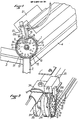
- Figure 1 shows a reading station for movable members 1 each equipped with a hanging rod 2 which are suspended, for example, parts for making clothes.
- each movable member 1 takes a precise position defined in this example by an angle provided between a guide rail 3 slightly descending and a guide rail 4 strongly rising.
- Each movable member 1 has an axis 5 on which a disk 6 is mounted to rotate freely.
- the latter has on one of its main faces a first annular area 7, concentric with the axis 5, preferably located at the periphery to have the largest possible diameter. In this range, radial grooves or grooves 8 are produced.
- the area 9 which directly follows the first area 7 has a succession of through holes 12 whose number and spacings are representative of an identification number.
- the next range 10, closer to the axis 5, has a succession of through holes 13 spaced at a constant pitch in correspondence with a reading rate or a clock rhythm.
- the holes 12 of the area 9 are on the same radial line respectively as a corresponding radial line of a hole 13 of the area 10.
- the area 11, closest to the axis 5, has a single through hole 14 located on the same radial line as a hole 13 in range 10, on which a hole 12 in range 9 may possibly be located.
- Hole 13 in range 10 corresponds to the emission of a start signal from the read operation during the rotation of the disc 6 around the axis 5.
- a nozzle 15 which is connected by a nozzle 16 to a source of compressed air, and a yoke 17 with two branches 17A, 17B which contain between them each disc 6 located at the reading station.
- the nozzle 15 is oriented to blow air in a direction transverse to the radial ridges 8 and almost tangential to the surface of the disc 6 in order to rotate the latter around the axis 5.
- the adjustment, using a screw, not shown, of the air flow blown through the nozzle 15, makes it possible to obtain a substantially constant speed of rotation of all the disks 5 at a value suitable for reading.
- a branch 17A of the yoke 17 located on one side of the discs 6, carries detectors, arranged radially in the direction of the axis 5, constituted by phototransistors respectively 18, 19, 20, each in correspondence with a range 9, 10, 11 holes. These phototransistors are connected to electronic circuits (not shown) known per se, included in a decoding apparatus 21.
- the opposite branch 17B of the yoke 17 located on the other side of the discs 6 carries emitters of infrared radiation (not visible in the drawings), arranged radially in the direction of the axis 5, each in correspondence with the phototransistors 18, 19 , 20. The latter are impressed by the radiation from the transmitters each time a hole in the disc 6 allows the radiation to pass.
- each disk 5 could be provided on tracks 9, 10, 11 , coding and reading of magnetic pads and the branch 17A detectors could be heads sensitive to the passage of magnetic pads.
- the solution described here is therefore preferable but not compulsory.
- the nozzle 15 could be installed on a branch of a yoke similar to the yoke 17 having a second branch located opposite the other main face of the discs 6.
- This second branch could carry a second compressed air blowing nozzle on radial grooves made on this other main face of the discs.
- Each disc 6 of each movable member 1 is provided in its range 9 with holes 12 whose number and spacings are specific to it and allow it to be identified.
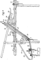
- FIG. 3 shows an example of use of the device of the invention which has just been described.
- Movable members 1 are moved on a general conveyor 22 along which are installed several work stations P.
- Each work station P is associated with a bypass line 23 which successively comprises an input switch blade 24, a path guide 25, a section 26 for stopping at the workstation P slightly inclined on the horizontal, a guide path for ascent 27, a guide path for descending 28, a switching blade 29 for reintroduction on the general conveyor 22.
- the reading station is located at the elbow made by the stop section 26 and the ascent guide path 27.
- the ascent of the movable members is carried out, after identification reading as explained above, using a pneumatic cylinder 30, partially shown, which controls a lifting device 31 included in a sheath 32. This device will not be described in detail because it is not part of the present the invention.
- the axis 5 which carries the disc 6 is also the axis of two rollers 33, 34 separated by an interval 35.
- the Ascent device comprises a retractable stop during the descent which is placed in the interval 35 to drive the movable member 1 upward during the ascent.
- the jack 30 lowers the ascent device 31 when a movable member 1 is stopped at the reading station.
- the exhaust side of the cylinder 30 during the descent of the ascent device has an air exhaust orifice which is connected by a flexible pipe 36 to the nozzle 16 for connection of the blowing nozzle.
- any other cylinder of an installation whose movement takes place at the time when a reading must be made could be connected by its exhaust orifice to the nozzle or to the blowing nozzles 15.
- the use of a jack intended to evacuate the movable members 1 from the reading station is particularly suitable since this jack comes into operation precisely at the time of an identification reading.
Abstract
Description
L'invention a pour objet un dispositif utilisable pour affecter un signe ou un numéro codé d'identification à un organe déplaçable, servant généralement à porter des pièces à travailler, et pour permettre la lecture de ce signe ou numéro d'identification à un poste de lecture convenablement équipé à cet effet afin de permettre de diriger ensuite ledit organe déplaçable vers un endroit déterminé, par exemple, un poste de travail.The subject of the invention is a device which can be used to assign a coded identification sign or number to a movable member, generally used to carry workpieces, and to allow this sign or identification number to be read at a station. reading device suitably equipped for this purpose in order to then direct said movable member to a determined location, for example, a work station.
On connaît déjà dans la littérature technique et dans la pratique, de nombreux dispositifs de codage et de lecture.Numerous coding and reading devices are already known in the technical literature and in practice.
Le dispositif de l'invention cherche à s'en distinguer par sa simplicité de réalisation, par son faible coût d'exécution et d'exploitation procurant cependant une sûreté de fonctionnement remarquable.The device of the invention seeks to be distinguished by its simplicity of implementation, by its low cost of execution and operation, however, providing remarkable operational reliability.
Un dispositif conforme à l'invention comprend d'une part sur l'organe déplaçable un disque conçu pour être monté libre en rotation autour d'un axe, un axe supporté par l'organe déplaçable et portant ce disque, ce dernier présentant au moins sur une de ses faces principales une première plage d'entraînement en rotation, annulaire, concentrique à l'axe, où se trouvent des stries substantiellement radiales dans l'ensemble, et plusieurs autres plages annulaires de codage et de lecture de diamètres différents concentriques à l'axe, sur lesquelles sont prévus des points détectables. D'autre part, à chaque poste de lecture une buse de soufflage d'un gaz sous pression est disposée pour envoyer un jet de gaz dans une direction transversale aux stries de la première plage du disque de chaque organe arrêté à ce poste et au moins une branche de lecture est supportée pour être disposée radialement dans l'ensemble en regard des plages de codage et de lecture de ce même disque, cette branche portant des détecteurs appropriés en correspondance avec chacune des plages de codage et de lecture du disque ; de façon connue en soi, ces détecteurs sont reliés fonctionnellement à des circuits électroniques de décodage.A device according to the invention comprises on the one hand on the movable member a disc designed to be mounted free in rotation about an axis, an axis supported by the movable member and carrying this disc, the latter having at least on one of its main faces a first rotary drive range, annular, concentric with the axis, where there are substantially radial grooves in the assembly, and several other annular coding and reading ranges of different diameters concentric with the axis, on which detectable points are provided. On the other hand, at each reading station a blowing nozzle for a pressurized gas is arranged to send a gas jet in a direction transverse to the striations of the first track of the disc of each member stopped at this station and at least a reading branch is supported so as to be disposed radially in the assembly opposite the coding and reading areas of this same disc, this branch carrying appropriate detectors in correspondence with each of the coding and reading areas of the disc; in a manner known per se, these detectors are functionally connected to electronic decoding circuits.
Selon un mode de réalisation de l'invention, il existe à chaque poste de lecture un étrier à deux branches parallèles et espacées pour pouvoir contenir librement entre elles un disque ; l'une des branches porte des émetteurs de rayonnement, de préférence en infrarouge et l'autre branche porte des phototransistors qui font partie des circuits électroniques de décodage ; de préférence, il existe trois plages de codage et de lecture ; une plage présente un trou pour l'émission d'un bit de démarrage de lecture, une plage présente une succession de trous pour l'émission de bits d'horloge et une autre plage du disque présente une succession de trous de codage.According to one embodiment of the invention, there is at each reading station a stirrup with two parallel branches spaced apart so as to be able to contain a disc freely between them; one of the branches carries emitters of radiation, preferably in infrared and the other branch carries phototransistors which are part of the electronic decoding circuits; preferably, there are three coding and reading ranges; one track has a hole for the transmission of a read start bit, one track has a succession of holes for the transmission of clock bits and another track of the disc has a succession of coding holes.
Dans un exemple particulièrement avantageux de réalisation de l'invention, dans une installation où il existe au moins un vérin pneumatique ayant à exécuter un mouvement au moment de l'opération de lecture du disque de chaque organe déplaçable, la buse de soufflage est raccordée à l'orifice d'échappement de l'air de ce vérin.In a particularly advantageous embodiment of the invention, in an installation where there is at least one pneumatic cylinder having to execute a movement during the reading operation of the disc of each movable member, the blowing nozzle is connected to the air exhaust port of this cylinder.
On donnera maintenant, sans intention limitative et sans exclure aucune variante, une description d'un exemple préféré de réalisation. On se reportera aux dessins annexés dans lesquels :
- la figure 1 est une vue de côté d'un poste de lecture avec un disque d'un organe déplaçable en cours de lecture ;
- la figure 2 est une vue en perspective du même poste de lecture ;
- la figure 3 est une vue générale d'une installation qui comprend un poste de lecture comme celui des figures 1 et 2 et un ensemble d'organes déplaçables munis chacun d'un disque de codage.
- Figure 1 is a side view of a reading station with a disc of a movable member during reading;
- Figure 2 is a perspective view of the same reading station;
- Figure 3 is a general view of an installation which includes a reading station like that of Figures 1 and 2 and a set of movable members each provided with a coding disc.
La figure 1 montre un poste de lecture pour des organes déplaçables 1 équipés chacun d'une tige de suspension 2 à laquelle sont suspendues, par exemple, des pièces pour la confection de vêtements. A ce poste de lecture, chaque organe déplaçable 1 vient prendre une position précise définie dans cet exemple par un angle prévu entre un rail de guidage 3 faiblement descendant et un rail de guidage 4 fortement montant.Figure 1 shows a reading station for
Chaque organe déplaçable 1 a un axe 5 sur lequel est monté libre en rotation un disque 6. Ce dernier présente sur une de ses faces principales une première plage annulaire 7, concentrique à l'axe 5, située de préférence à la périphérie pour avoir le diamètre le plus grand possible. Dans cette plage, sont réalisées des stries ou rainures radiales 8. Ensuite, plus près de l'axe 5, il existe trois plages annulaires successives, respectivement 9, 10, 11, concentriques, de diamètres successivement réduits, pour le codage et la lecture. La plage 9 qui suit directement la première plage 7 présente une succession de trous traversants 12 dont le nombre et les espacements sont représentatifs d'un numéro d'identification. La plage suivante 10, plus proche de l'axe 5, présente une succession de trous traversants 13 espacés d'un pas constant en correspondance avec une cadence de lecture ou un rythme d'horloge. Les trous 12 de la plage 9 sont sur une même ligne radiale respectivement qu'une ligne radiale correspondante d'un trou 13 de la plage 10. La plage 11, la plus proche de l'axe 5, présente un seul trou traversant 14 situé sur une même ligne radiale qu'un trou 13 de la plage 10, sur laquelle peut se trouver éventuellement un trou 12 de la plage 9. Le trou 13 de la plage 10 correspond à l'émission d'un signal de démarrage de l'opération de lecture pendant la rotation du disque 6 autour de l'axe 5.Each
Au poste de lecture sont installées, de manière fixe et permanente, une buse 15, qui est raccordée par un embout 16 à une source d'air comprimé, et une chape 17 à deux branches 17A, 17B qui contiennent entre elles chaque disque 6 situé au poste de lecture.At the reading station are installed, permanently and permanently, a
La buse 15 est orientée pour souffler de l'air dans une direction transversale aux stries radiales 8 et presque tangentielle à la surface du disque 6 afin de faire tourner ce dernier autour de l'axe 5. Le réglage, à l'aide d'une vis non représentée, du débit d'air soufflé à travers la buse 15, permet d'obtenir une vitesse de rotation substantiellement constante de tous les disques 5 à une valeur convenable pour la lecture.The
Une branche 17A de la chape 17 située sur un côté des disques 6, porte des détecteurs, disposés radialement en direction de l'axe 5, constitués par des phototransistors respectivement 18, 19, 20, en correspondance chacun avec une plage 9, 10, 11 de trous. Ces phototransistors sont reliés à des circuits électroniques (non représentés) connus en soi, inclus dans un appareil de décodage 21.A
La branche opposée 17B de la chape 17 située sur l'autre côté des disques 6 porte des émetteurs de rayonnement infrarouge (non visibles sur les dessins), disposés radialement en direction de l'axe 5, en correspondance chacun avec les phototransistors 18, 19, 20. Ces derniers sont impressionnés par le rayonnement des émetteurs chaque fois qu'un trou du disque 6 permet le passage du rayonnement.The opposite branch 17B of the
Il est évident que l'on pourrait choisir d'autres genres de détecteurs et d'autres moyens d'agir sur eux à l'aide des disques 5. Par exemple, chaque disque 5 pourrait être pourvu sur les plages 9, 10, 11, de codage et de lecture de plots magnétiques et les détecteurs de la branche 17A pourraient être des têtes sensibles au passage des plots magnétiques. La solution décrite ici est donc préférable mais non obligatoire.It is obvious that one could choose other kinds of detectors and other means of acting on them using the disks 5. For example, each disk 5 could be provided on
La buse 15 pourrait être installée sur une branche d'une chape analogue à la chape 17 ayant une deuxième branche située en regard de l'autre face principale des disques 6. Cette deuxième branche pourrait porter une deuxième buse de soufflage d'air comprimé sur des stries radiales réalisées sur cette autre face principale des disques.The
Le fonctionnement du dispositif de l'invention est le suivantThe operation of the device of the invention is as follows
Chaque disque 6 de chaque organe déplaçable 1 est pourvu dans sa plage 9 de trous 12 dont le nombre et les espacements lui sont particuliers et permettent de l'identifier.Each
Quand un organe déplaçable 1 est arrêté au poste de lecture, de l'air comprimé envoyé à la buse ou aux buses de soufflage 15 provoque la rotation du disque 6. Le trou 14 de la plage 11 permet au cours d'un tour du disque 6 l'envoi, par le détecteur 20 correspondant influencé par le rayonnement de l'émetteur qui lui est associé, d'un signal du début de lecture. La lecture se fait à travers les trous d'identification 12 de la plage 9 quand le détecteur 18 correspondant est influencé par le rayonnement de l'émetteur qui lui est associé. Les trous 13 de la plage 10 provoquent l'émission de signaux d'horloge qui permettent de connaître la vitesse exacte de rotation du disque 6. Ce dernier est réalisable en matière plastique ; les trous 12 du codage d'identification correspondent de préférence à un code binaire de 16 bits. La lecture est répétée sur plusieurs tours successifs, six par exemple, du disque 6, pendant une durée totale de quatre secondes par exemple. Quand l'organe déplaçable 1 arrêté au poste de lecture a été identifié, il est dirigé ensuite vers le poste de travail suivant où il doit s'arrêter.When a
La figure 3 montre un exemple d'utilisation du dispositif de l'invention que l'on vient de décrire.FIG. 3 shows an example of use of the device of the invention which has just been described.
Des organes déplaçables 1 sont déplacés sur un transporteur général 22 le long duquel sont installés plusieurs postes de travail P. Chaque poste de travail P est associé à une ligne de dérivation 23 qui comprend successivement une lame d'aiguillage d'entrée 24, un chemin de guidage descendant 25, un tronçon 26 d'arrêt au poste de travail P faiblement incliné sur l'horizontale, un chemin de guidage de remontée 27, un chemin de guidage descendant 28, une lame d'aiguillage 29 de réintroduction sur le transporteur général 22. Le poste de lecture est situé au coude fait par le tronçon d'arrêt 26 et le chemin de guidage de remontée 27. La remontée des organes déplaçables est exécutée, après lecture d'identification comme expliqué ci-dessus, à l'aide d'un vérin pneumatique 30, représenté partiellement, qui commande un dispositif de remontée 31 inclus dans un fourreau 32. Ce dispositif ne sera pas décrit en détail parce qu'il ne fait pas partie de la présente invention. Toutefois, en rapport avec la présente invention, on peut voir sur la figure 2 que sur chaque organe déplaçable 1, l'axe 5 qui porte le disque 6 est aussi l'axe de deux roulettes 33, 34 séparées par un intervalle 35. Le dispositif de remontée comprend une butée escamotable pendant la descente qui vient se placer dans l'intervalle 35 pour entraîner l'organe déplaçable 1 vers le haut pendant la remontée. Le vérin 30 fait descendre le dispositif de remontée 31 quand un organe déplaçable 1 est arrêté au poste de lecture. Le côté de l'échappement du vérin 30 pendant la descente du dispositif de remontée a un orifice d'échappement de l'air qui est raccordé par un tuyau souple 36 à l'embout 16 de raccordement de la buse de soufflage. Ainsi, aucune source d'énergie supplémentaire n'est nécessaire pour l'exécution de l'opération de lecture.
Bien entendu, tout autre vérin d'une installation dont le mouvement a lieu au moment où doit être faite une lecture, pourrait être raccordé par son orifice d'échappement à la buse ou aux buses de soufflage 15. Toutefois, l'emploi d'un vérin destiné à évacuer du poste de lecture les organes déplaçables 1 est particulièrement approprié puisque ce vérin entre en fonctionnement justement au moment d'une lecture d'identification.Of course, any other cylinder of an installation whose movement takes place at the time when a reading must be made, could be connected by its exhaust orifice to the nozzle or to the blowing
Claims (6)
Priority Applications (1)
| Application Number | Priority Date | Filing Date | Title |
|---|---|---|---|
| AT86402134T ATE49310T1 (en) | 1985-10-01 | 1986-09-30 | CODING AND SCANNING DEVICE FOR MOVABLE CARRIER ELEMENTS FOR GUIDING WORKPIECES TO SPECIFIC WORKSHOPS. |
Applications Claiming Priority (2)
| Application Number | Priority Date | Filing Date | Title |
|---|---|---|---|
| FR8514514A FR2588137B1 (en) | 1985-10-01 | 1985-10-01 | CODING AND READING DEVICE FOR PARTS HOLDERS TO BE DIRECTED TO SPECIFIED WORKSTATIONS. |
| FR8514514 | 1985-10-01 |
Publications (2)
| Publication Number | Publication Date |
|---|---|
| EP0220101A1 EP0220101A1 (en) | 1987-04-29 |
| EP0220101B1 true EP0220101B1 (en) | 1990-01-03 |
Family
ID=9323408
Family Applications (1)
| Application Number | Title | Priority Date | Filing Date |
|---|---|---|---|
| EP86402134A Expired - Lifetime EP0220101B1 (en) | 1985-10-01 | 1986-09-30 | Coding and reading device for movable carriers directing work pieces to predetermined working stations |
Country Status (9)
| Country | Link |
|---|---|
| US (1) | US4719449A (en) |
| EP (1) | EP0220101B1 (en) |
| JP (1) | JPS6282323A (en) |
| AT (1) | ATE49310T1 (en) |
| CA (1) | CA1252889A (en) |
| DE (1) | DE3668084D1 (en) |
| ES (1) | ES2002782A6 (en) |
| FR (1) | FR2588137B1 (en) |
| PT (1) | PT83383B (en) |
Families Citing this family (21)
| Publication number | Priority date | Publication date | Assignee | Title |
|---|---|---|---|---|
| JPH01115520A (en) * | 1987-10-27 | 1989-05-08 | Fanuc Ltd | Automatic wire connection end detecting system |
| JPH0361211A (en) * | 1989-07-27 | 1991-03-18 | Brother Ind Ltd | Hanger detecting device in hanger conveyer system |
| US4982189A (en) * | 1989-12-05 | 1991-01-01 | Crown Equipment Corp. | Encoder with wide index |
| JPH03113124U (en) * | 1990-03-06 | 1991-11-19 | ||
| JP2961810B2 (en) * | 1990-05-17 | 1999-10-12 | ブラザー工業株式会社 | Detector for transport system |
| US5571067A (en) * | 1993-11-19 | 1996-11-05 | Ranpak Corp. | Cushioning conversion machine including a length measuring device |
| US6524230B1 (en) | 1994-07-22 | 2003-02-25 | Ranpak Corp. | Packing material product and method and apparatus for making, monitoring and controlling the same |
| DE785862T1 (en) * | 1994-07-22 | 1997-08-28 | Harding, Joseph, J., Mentor, Oh 44060, Us | COMPUTER CONTROLLED POLSFER CONVERSION MACHINE |
| US6179762B1 (en) | 1994-07-22 | 2001-01-30 | Ranpak Corp. | Cushioning conversion machine |
| US5746005A (en) * | 1996-10-22 | 1998-05-05 | Powerhorse Corporation | Angular position sensor |
| US5829231A (en) * | 1996-11-14 | 1998-11-03 | Ranpak Corporation | Automated cushioning producing and filling system |
| US6170162B1 (en) * | 1999-05-27 | 2001-01-09 | Sarcos, L.C. | Rotary displacement system using differential measuring |
| JP3376546B2 (en) * | 2000-06-20 | 2003-02-10 | 理英 近藤 | Pen-shaped bending wire length measuring instrument |
| DE10102278B4 (en) * | 2001-01-18 | 2004-10-28 | Raytheon Marine Gmbh | Data transmission path on an n.360 ° storage |
| CN100457556C (en) * | 2002-11-01 | 2009-02-04 | 兰帕克公司 | Packaging system with void fill measurement |
| EP1528369B1 (en) * | 2003-10-27 | 2014-03-12 | SICK STEGMANN GmbH | Optical rotation angle sensor |
| US7287333B1 (en) * | 2006-05-19 | 2007-10-30 | Her Yuan Chyun Co., Ltd. | Signal detecting device |
| CN102963700B (en) * | 2012-11-21 | 2015-06-17 | 深圳市华星光电技术有限公司 | Mechanical device |
| WO2015159392A1 (en) * | 2014-04-16 | 2015-10-22 | 三菱電機株式会社 | Elevator position detection device |
| IT201700078393A1 (en) * | 2017-07-13 | 2019-01-13 | Gd Spa | Identification system of a component of a packaging machine. |
| CN116689316B (en) * | 2023-08-08 | 2023-10-20 | 江苏安欣医疗科技有限公司 | Surrounding type detection equipment for straight tube of electric endoscope anastomat |
Family Cites Families (8)
| Publication number | Priority date | Publication date | Assignee | Title |
|---|---|---|---|---|
| DE1187384B (en) * | 1956-05-16 | 1965-02-18 | Philips Nv | Device for measuring angles by pulse counting |
| DE1267003B (en) * | 1963-05-02 | 1968-04-25 | Zuse K G | Device for scanning digital data on recording media |
| US3594735A (en) * | 1968-08-26 | 1971-07-20 | Exact Weight Scale Co The | Data retrieval apparatus |
| CH512786A (en) * | 1970-03-11 | 1971-09-15 | Hasler Ag | Machine-readable magnetic information carrier |
| SE385988B (en) * | 1973-06-21 | 1976-07-26 | Platmanufaktur Ab | IDENTIFICATION DEVICE FOR FORM NUMBER READING ON MACHINE-FORMED PRODUCTS EXV. PLASTIC OR GLASS PRODUCTS |
| JPS5261063A (en) * | 1975-11-15 | 1977-05-20 | Yamakawa Denshi Kk | Apparatus for reading out information of mobile body |
| JPS5851073B2 (en) * | 1975-11-25 | 1983-11-14 | アライ ソウイチロウ | Kagakusen Initaisurunatsusenyakushiyokuhou |
| DE2943622A1 (en) * | 1979-10-29 | 1981-05-07 | Hermut 2072 Bargteheide Schittko | METHOD AND DEVICE FOR CODING AND DECODING PARTS |
-
1985
- 1985-10-01 FR FR8514514A patent/FR2588137B1/en not_active Expired
-
1986
- 1986-08-18 US US06/897,265 patent/US4719449A/en not_active Expired - Fee Related
- 1986-09-05 CA CA000517550A patent/CA1252889A/en not_active Expired
- 1986-09-16 PT PT83383A patent/PT83383B/en not_active IP Right Cessation
- 1986-09-30 AT AT86402134T patent/ATE49310T1/en not_active IP Right Cessation
- 1986-09-30 JP JP61230190A patent/JPS6282323A/en active Pending
- 1986-09-30 EP EP86402134A patent/EP0220101B1/en not_active Expired - Lifetime
- 1986-09-30 ES ES8602298A patent/ES2002782A6/en not_active Expired
- 1986-09-30 DE DE8686402134T patent/DE3668084D1/en not_active Expired - Fee Related
Also Published As
| Publication number | Publication date |
|---|---|
| EP0220101A1 (en) | 1987-04-29 |
| PT83383A (en) | 1986-10-01 |
| FR2588137A1 (en) | 1987-04-03 |
| PT83383B (en) | 1992-10-30 |
| US4719449A (en) | 1988-01-12 |
| JPS6282323A (en) | 1987-04-15 |
| FR2588137B1 (en) | 1988-01-08 |
| ATE49310T1 (en) | 1990-01-15 |
| ES2002782A6 (en) | 1988-10-01 |
| CA1252889A (en) | 1989-04-18 |
| DE3668084D1 (en) | 1990-02-08 |
Similar Documents
| Publication | Publication Date | Title |
|---|---|---|
| EP0220101B1 (en) | Coding and reading device for movable carriers directing work pieces to predetermined working stations | |
| US4469217A (en) | Apparatus for transport of capsules and the like | |
| US4441853A (en) | Disc orienting device | |
| FR2870934A1 (en) | CONTOUR READING APPARATUS COMPRISING A ROTATING MOBILE PROBE | |
| ATE112230T1 (en) | GROUPING SETUP. | |
| FR2661226B1 (en) | BEARING HUB EQUIPPED WITH A ROTATION SPEED DETECTION DEVICE. | |
| DE60006807D1 (en) | DEVICE FOR STRAIGHTING LIKE OBJECTS, IN PARTICULAR FOR FRUIT | |
| EP1583617A2 (en) | Product conveying device, in particular fruits or vegetables, adapted to at least weight-based sorting of the products | |
| ES2046436T3 (en) | SYSTEM TO SEPARATE EQUIDISTANTLY AND TRANSFER ITEMS FROM A FIRST TO A SECOND CONVEYOR. | |
| CA2312038A1 (en) | Conveyor device for products, in particular fruits, for feeding a unit sorting said products | |
| CA2294371A1 (en) | Spindle disc for high speed can decorators | |
| EP1258878A3 (en) | Rotational operation mechanism and music playback apparatus using the mechanism | |
| KR910000333A (en) | Tire assembly device | |
| GB1325032A (en) | Apparatus for peeling fruit | |
| FR2364290A1 (en) | DEVICE FOR REFINING FIBER MATERIALS | |
| HU177097B (en) | Device for pulling up flexible ring springs especiallyonto packing rings | |
| ES2084870T3 (en) | PROVISION FOR THE DETECTION WITHOUT CONTACT OF THE NUMBER OF REVOLUTIONS OR POSITION OF A PART OF ROTARY TRANSMITTER. | |
| ES456780A2 (en) | Labeling station of a machine for labeling objects, especially bottles | |
| ES2157540T3 (en) | LABELING MACHINE | |
| EP0574422B1 (en) | Method for heat treating glassware and crystalware articles in a plane perpendicular to their rotation axis, and device for implementing such method | |
| FR2574256A1 (en) | PROCESS FOR THE CONTINUOUS PRODUCTION OF TWO CIGARETTES CURRENT CONTROLLED BY GRAPHIC SIGNAL DETECTORS | |
| JPS58172109A (en) | Distributing apparatus for bottle | |
| FR2599490A1 (en) | SYSTEM FOR DETECTING THE WEAR OF LINKS AND BOLTS OF TRANSPORT CHAINS | |
| EP0924697A3 (en) | System for reproducing a disc | |
| WO1996034386A3 (en) | Disc changer with rotatable disc support and disc player including the disc changer |
Legal Events
| Date | Code | Title | Description |
|---|---|---|---|
| PUAI | Public reference made under article 153(3) epc to a published international application that has entered the european phase |
Free format text: ORIGINAL CODE: 0009012 |
|
| 17P | Request for examination filed |
Effective date: 19861002 |
|
| AK | Designated contracting states |
Kind code of ref document: A1 Designated state(s): AT BE CH DE GB IT LI LU NL SE |
|
| 17Q | First examination report despatched |
Effective date: 19890614 |
|
| GRAA | (expected) grant |
Free format text: ORIGINAL CODE: 0009210 |
|
| AK | Designated contracting states |
Kind code of ref document: B1 Designated state(s): AT BE CH DE GB IT LI LU NL SE |
|
| PG25 | Lapsed in a contracting state [announced via postgrant information from national office to epo] |
Ref country code: SE Effective date: 19900103 |
|
| REF | Corresponds to: |
Ref document number: 49310 Country of ref document: AT Date of ref document: 19900115 Kind code of ref document: T |
|
| ITF | It: translation for a ep patent filed |
Owner name: BARZANO'E ZANARDO S.P.A. |
|
| GBT | Gb: translation of ep patent filed (gb section 77(6)(a)/1977) | ||
| REF | Corresponds to: |
Ref document number: 3668084 Country of ref document: DE Date of ref document: 19900208 |
|
| PGFP | Annual fee paid to national office [announced via postgrant information from national office to epo] |
Ref country code: GB Payment date: 19900921 Year of fee payment: 5 |
|
| PGFP | Annual fee paid to national office [announced via postgrant information from national office to epo] |
Ref country code: AT Payment date: 19900926 Year of fee payment: 5 |
|
| PGFP | Annual fee paid to national office [announced via postgrant information from national office to epo] |
Ref country code: BE Payment date: 19900927 Year of fee payment: 5 |
|
| ITTA | It: last paid annual fee | ||
| PG25 | Lapsed in a contracting state [announced via postgrant information from national office to epo] |
Ref country code: LU Free format text: LAPSE BECAUSE OF NON-PAYMENT OF DUE FEES Effective date: 19900930 |
|
| PGFP | Annual fee paid to national office [announced via postgrant information from national office to epo] |
Ref country code: NL Payment date: 19900930 Year of fee payment: 5 |
|
| PLBE | No opposition filed within time limit |
Free format text: ORIGINAL CODE: 0009261 |
|
| STAA | Information on the status of an ep patent application or granted ep patent |
Free format text: STATUS: NO OPPOSITION FILED WITHIN TIME LIMIT |
|
| PGFP | Annual fee paid to national office [announced via postgrant information from national office to epo] |
Ref country code: CH Payment date: 19901101 Year of fee payment: 5 |
|
| PGFP | Annual fee paid to national office [announced via postgrant information from national office to epo] |
Ref country code: DE Payment date: 19901112 Year of fee payment: 5 |
|
| 26N | No opposition filed | ||
| PG25 | Lapsed in a contracting state [announced via postgrant information from national office to epo] |
Ref country code: LI Effective date: 19910930 Ref country code: GB Effective date: 19910930 Ref country code: CH Effective date: 19910930 Ref country code: BE Effective date: 19910930 Ref country code: AT Effective date: 19910930 |
|
| BERE | Be: lapsed |
Owner name: JICE AUTOMATION Effective date: 19910930 |
|
| PG25 | Lapsed in a contracting state [announced via postgrant information from national office to epo] |
Ref country code: NL Effective date: 19920401 |
|
| NLV4 | Nl: lapsed or anulled due to non-payment of the annual fee | ||
| GBPC | Gb: european patent ceased through non-payment of renewal fee | ||
| REG | Reference to a national code |
Ref country code: CH Ref legal event code: PL |
|
| PG25 | Lapsed in a contracting state [announced via postgrant information from national office to epo] |
Ref country code: DE Effective date: 19920602 |
|
| PGFP | Annual fee paid to national office [announced via postgrant information from national office to epo] |
Ref country code: LU Payment date: 19940630 Year of fee payment: 9 |
|
| EPTA | Lu: last paid annual fee | ||
| PG25 | Lapsed in a contracting state [announced via postgrant information from national office to epo] |
Ref country code: IT Free format text: LAPSE BECAUSE OF NON-PAYMENT OF DUE FEES;WARNING: LAPSES OF ITALIAN PATENTS WITH EFFECTIVE DATE BEFORE 2007 MAY HAVE OCCURRED AT ANY TIME BEFORE 2007. THE CORRECT EFFECTIVE DATE MAY BE DIFFERENT FROM THE ONE RECORDED. Effective date: 20050930 |