EP0219888B1 - Closure systems - Google Patents
Closure systems Download PDFInfo
- Publication number
- EP0219888B1 EP0219888B1 EP86200826A EP86200826A EP0219888B1 EP 0219888 B1 EP0219888 B1 EP 0219888B1 EP 86200826 A EP86200826 A EP 86200826A EP 86200826 A EP86200826 A EP 86200826A EP 0219888 B1 EP0219888 B1 EP 0219888B1
- Authority
- EP
- European Patent Office
- Prior art keywords
- closure
- door
- bracket
- floor
- wheel
- Prior art date
- Legal status (The legal status is an assumption and is not a legal conclusion. Google has not performed a legal analysis and makes no representation as to the accuracy of the status listed.)
- Expired
Links
- 230000000903 blocking effect Effects 0.000 claims description 5
- 230000007246 mechanism Effects 0.000 description 14
- 230000037361 pathway Effects 0.000 description 2
- 238000010276 construction Methods 0.000 description 1
- 230000008878 coupling Effects 0.000 description 1
- 238000010168 coupling process Methods 0.000 description 1
- 238000005859 coupling reaction Methods 0.000 description 1
- 238000005096 rolling process Methods 0.000 description 1
Images


Classifications
-
- B—PERFORMING OPERATIONS; TRANSPORTING
- B64—AIRCRAFT; AVIATION; COSMONAUTICS
- B64C—AEROPLANES; HELICOPTERS
- B64C1/00—Fuselages; Constructional features common to fuselages, wings, stabilising surfaces or the like
- B64C1/14—Windows; Doors; Hatch covers or access panels; Surrounding frame structures; Canopies; Windscreens accessories therefor, e.g. pressure sensors, water deflectors, hinges, seals, handles, latches, windscreen wipers
- B64C1/1407—Doors; surrounding frames
- B64C1/1415—Cargo doors, e.g. incorporating ramps
-
- B—PERFORMING OPERATIONS; TRANSPORTING
- B64—AIRCRAFT; AVIATION; COSMONAUTICS
- B64C—AEROPLANES; HELICOPTERS
- B64C1/00—Fuselages; Constructional features common to fuselages, wings, stabilising surfaces or the like
- B64C1/14—Windows; Doors; Hatch covers or access panels; Surrounding frame structures; Canopies; Windscreens accessories therefor, e.g. pressure sensors, water deflectors, hinges, seals, handles, latches, windscreen wipers
- B64C1/1407—Doors; surrounding frames
Definitions
- the present invention relates to a closure system in combination with a structure having a vertically extending wall with a doorway therein and a floor extending from said wall at the lower edge thereof, said closure system comprising:
- Such a closure system is known from DE-A 2 008 301.
- the most important application of my invention involves an aircraft door which can be opened during flight and then moved to a location remote from the doorway it is provided to block to facilitate the deployment of equipment, parachutists, etc., through the doorway.
- Aircraft doors which can be opened during flight have been proposed.
- One such proposal involves a track-mounted inwardly opening door.
- This arrangement has the decided disadvantage that the track mechanism takes up considerable valuable space in the interior of the aircraft.
- the track mechanism also impedes movement of men and material in its vicinity.
- This is achieved according to the invention in that the closure opens inwardly and comprises wheel means rotatably attached to the lower end thereof, and in that the bracket means is removably latched to the structure.
- the closure system I has invented and disclosed herein includes an inwardly opening, plug-fitting door coupled by a conventional catch to the structure, e.g. the fuselage of an aircraft in which it is installed at the upper end of the door.
- the lower end of the door carries a wheel or roller, and that end of the door is detachably supported in a bracket latched to the floor of the aircraft.
- the door is quickly and simply removed for transfer to an out-of-the-way location by opening the catch at the upper end of the door and rotating the door inwardly about horizontally extending, door- carried lugs seated in the door-supporting bracket until the roller is lowered into engagement with the floor of the aircraft.
- the door cams the lugs by which it is supported upwardly and out of recesses in the bracket in which they are seated, allowing the operator to roll the door away to, and stow it in, an appropriate out-of-the-way location.
- Latches incorporated in the door-supporting bracket are then released, allowing the latter to be removed and stowed away to provide a clear pathway to the aircraft's doorway.
- the bracket may be used to secure in place the lower end of the door also removed to that location for storage.
- this novel closure system simply and inexpensively solves the problem of furnishing access through the doorway of a high-speed aircraft during flight. This is accomplished in a manner which does not require that permanently mounted tracks, brackets, or other components be located in the aircraft's interior, and a clear pathway to the aircraft's doorway is provided when the door is removed. Furthermore, the door can be easily removed, stowed, and returned to its doorway blocking position by a single person.
- figure 1 depicts the fuselage 20 of a high-speed aircraft. That fuselage has a doorway 22 which can be closed or blocked by the plug-fitting door 24 of a closure system constructed in accord with, and embodying, the principles of the present invention and identified by reference character 26.
- closure system 26 Aside from door 24, the major components of closure system 26 include a catch mechanism 28 for latching the upper end of door 24 to the fuselage 20 of the aircraft, a wheel 30 which makes door 24 mobile and allows it to be rolled to an out-of-the-way storage location by a single person, and a door-supporting bracket 32 removably latched to the floor 34 of the aircraft. This bracket supports the lower end of door 24 from the floor of the aircraft in the illustrated position in which that door blocks doorway 22.
- the illustrated upper catch 28 is the one conventionally employed on the doors of a Boeing 737 twin- jet. For this reason that component of closure system 26 will not be disclosed herein.
- the other components of the closure system, except for the door iself (which can be of any desired construction), are described below.
- FIG. 2 two parallel, spaced apart wheel supports 36 and 38 are bolted or otherwise attached to door 24 at the lower end 40 thereof.
- Journalled in supports 36 and 38 is a horizontally extending axle 42 for wheel 30.
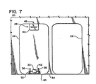
- Door 24 can be rolled on this wheel between the doorway obstructing or blocking position shown in FIG. 1 to the out-of-the-way storage position shown in FIG. 7 and identified by reference character 46.
- the detachable, floor-mounted, bracket 32 has a platform 48 with vertically extending stanchions 50 and 52 at the opposite ends thereof.
- upwardly extending, inwardly opening recesses 54 are formed in stanchions 50 and 52. These recesses are configured to provide seats for horizontally extending, door supporting, lugs 56 (only one shown). These lugs are fixed to the door mounted, wheel-supporting brackets 36 and 38 and extend in opposite directions from those supports along a horizontal axis parallel to, but spaced from, the horizontal axis of rotation of wheel-supporting axle 42.
- a bracket retaining track 58 is mounted in the floor 34 of the aircraft parallel to vertically extending fuselage wall 60.
- track 58 has an upwardly opening, C-Sectioned channel 60 surmounted by a keeper which is flat, horizontally oriented keyway 62.
- the track is mounted immediately subjacent the floor 34 of the aircraft and is reachable through an elongated slot 64 in that floor.
- Openings 66 of relatively larger diameter are alternated with slotted detents 68 in the keyway 62 of track 58.
- Aircraft of the type for which the closure systems disclosed herein are particularly designed will typically have a track of the character and orientation just described as original equipment.
- the illustrated arrangement for example, is that utilized by Boeing Commercial Aircraft Company to lock passenger seats in place.
- door-supporting bracket 32 also includes two identical latching mechanisms 70 and 72 for detachably coupling the bracket to the floor-mounted track 58 just described.
- Latching mechanism 70 shown in detail in FIG. 5 includes a stem 74, a latch actuator 76, and a retainer 78.
- Stem 74 is mounted for up-and-down, vertical sliding movement in a horizontal ledge 80 which is integral with, and extends toward the center of bracket platform 48 from, the stanchion 50 at the end of bracket 32.
- Retainer 78 is integral with the lower end of stem 74 and is dimensioned so that it can move freely upward through keyway 62 of track 58 when it is positioned opposite one of the enlarged openings 66 through the keyway but will be trapped below and against a keyway detent 68 when it is located opposite one of those detents 68.
- Latch actuator 76 includes a lever 82 fixed by a pivot pin 84 to the upper end of stem 74. Formed at that end of lever 82 is a downwardly extending cam 86. That cam is engageable with the upper surface 88 of ledge 80 to displace stem 74 upwardly and clamp retainer 78 against the lower side of keyway 62, thereby securely fixing bracket 32 to track 58 when lever 82 is rotated in a clockwise direction from the "unlatch" position shown in FIG. 6 to the "latch" position of FIG. 5.
- the first step in removing door 24 to permit movement through doorway 22 is to raise handle 90 of catch mechanism 28. This releases catches (not shown) which engage the door casing. Door 24 can subsequently be pulled inwardly and downwardly into the aircraft's interior.
- Raising handle 90 also equalizes the pressure in the aircraft fuselage with the ambient pressure through an also conventional port so that artifacts in the aircraft and/or persons therein will not be thrown about the compartment or blown out through the doorway when door 24 is opened.
- Door 24 is rotated inwardly and downwardly in a clockwise direction from the doorway blocking position shown in FIG. 3 to the position shown in full lines in FIG. 4 after the catches are released.
- wheel-supporting brackets 36 and 38 rotate in stanchions 50 and 52 of door-supporting bracket 32, lowering wheel 30 to the floor 34 of the aircraft.
- camming lugs 56 upwardly in recesses or slots 54 until the lugs engage the upper ends 92 of those slots. That aligns lugs 56 with the horizontal, inwardly facing openings 94 to recesses 54 and alerts the operator that this position has been reached and that door 24 can consequently be rolled away from bracket 32.
- door 24 is rolled on wheel 30 to an out-of-the-way storage position such as that mentioned above and identified by reference character 46 in FIG. 7.
- bracket 32 Once door 24 has cleared bracket 32, the levers 82 of latches 70 and 72 are rotated counterclockwise to the position shown in FIG. 6, allowing the retainers 78 at the lower ends of stems 74 to drop away from detents 68 of keyway 62 and release the frictional connection between the retainers and the detents. Bracket 32 is then slid to the left (or right) as shown in FIG. 2 with latch stems 74 sliding through the slots 96 in detents 68 to align retainers 78 with the openings 66 in keyway 62 through which they are dimensioned to pass. Bracket 32 is then lifted off track 58 with retainers 78 moving up through openings 66 and moved out of the way to provide a clear path to doorway 22.
- bracket 32 can be moved to location 46 and reinstalled by reversing the sequences of bracket removal steps just described to support the lower end of door 24 at that location.
- a mechanism (not shown) which is cooperable with the catch mechanism 28 of door 24 to secure the upper end of the door in place.
- This mechanism will typically be attached to the aircraft's overhead storage bins if the aircraft is so equipped. Otherwise, the catch associated mechanism will simply be mounted on the wall of the fuselage.
- a second door-supporting bracket like that described above or even a different type of mechanism can be employed to support the lower end of door 24 at the storage location rather than installing there the bracket employed at doorway 22.
- Plug-fitting door 24 is reinstalled in the position shown in FIG. 1 to block doorway 22 by reversing the sequence of steps just described; i.e., by: (1) pulling handle 90 of catch mechanism 28 upwardly to release the upper end of the door, (2) rotating the door inwardly and downwardly about lugs 56 to lower wheel 30 to the floor 34 of the aircraft and release it from bracket 32, (3) releasing the latter from the track 58 (or the like) at location 46 and re- installing the bracket at the location shown in FIG. 2, (4) rolling door 24 on wheel 30 to the location shown in that figure and in FIG.
Description
- The present invention relates to a closure system in combination with a structure having a vertically extending wall with a doorway therein and a floor extending from said wall at the lower edge thereof, said closure system comprising:
- - a removable closure for blocking said doorway; and
- - bracket means for detachably securing the lower end of said closure to said structure.
- Such a closure system is known from DE-A 2 008 301.
- At the present time the most important application of my invention involves an aircraft door which can be opened during flight and then moved to a location remote from the doorway it is provided to block to facilitate the deployment of equipment, parachutists, etc., through the doorway.
- The principles of the present invention will be developed primarily by relating them to the just-identified application of my invention. It is to be understood that this is being done for the sake of convenience and clarity and is not intended to limit the scope of the invention as defined in the appended claims.
- A demand exists for jet aircraft doors which can be opened during flight for the deployment of, for example, paratroopers and other chutists, rescue equipment, disasterrelief items, and other supplies and equipment. The alternative, removing the door before take-off, is impractical as the compartment sealed by the door could neither be heated nor pressurized during flight.
- Many jet aircraft doors open outwardly. They cannot be opened during flight because, at the high speeds at which jet aircraft travel, the door would be torn away by the air rushing past the aircraft.
- Aircraft doors which can be opened during flight have been proposed. One such proposal involves a track-mounted inwardly opening door. This arrangement has the decided disadvantage that the track mechanism takes up considerable valuable space in the interior of the aircraft. The track mechanism also impedes movement of men and material in its vicinity.
- Another heretofore made proposal involves a plug fitting door which is latched to the fuselage of the aircraft at its upper end and coupled at its lower end to a bracket permanently mounted on the aircraft floor. This arrangement has the disadvantage that two men are required to remove and carry away the door. Also, the floor-mounted bracket can interfere with the movement of supplies, equipment, personnel, etc. through the doorway.
- It is therefore an object of the present invention to provide a closure system having a door which can be removed and stowed in an out-of-the-way location by a single person, and not employing tracks, permanently mounted brackets or other components which protrude above the floor of the structure, especially an aircraft and would thereby interfere with the movement of equipment, supplies, or personnel through the doorway. This is achieved according to the invention in that the closure opens inwardly and comprises wheel means rotatably attached to the lower end thereof, and in that the bracket means is removably latched to the structure.
- In general, the closure system I have invented and disclosed herein includes an inwardly opening, plug-fitting door coupled by a conventional catch to the structure, e.g. the fuselage of an aircraft in which it is installed at the upper end of the door.
- The lower end of the door carries a wheel or roller, and that end of the door is detachably supported in a bracket latched to the floor of the aircraft.
- The door is quickly and simply removed for transfer to an out-of-the-way location by opening the catch at the upper end of the door and rotating the door inwardly about horizontally extending, door- carried lugs seated in the door-supporting bracket until the roller is lowered into engagement with the floor of the aircraft. Continued inward and downward rotation of the door cams the lugs by which it is supported upwardly and out of recesses in the bracket in which they are seated, allowing the operator to roll the door away to, and stow it in, an appropriate out-of-the-way location. Latches incorporated in the door-supporting bracket are then released, allowing the latter to be removed and stowed away to provide a clear pathway to the aircraft's doorway. In the location in which it is stored the bracket may be used to secure in place the lower end of the door also removed to that location for storage.
- Thus, this novel closure system simply and inexpensively solves the problem of furnishing access through the doorway of a high-speed aircraft during flight. This is accomplished in a manner which does not require that permanently mounted tracks, brackets, or other components be located in the aircraft's interior, and a clear pathway to the aircraft's doorway is provided when the door is removed. Furthermore, the door can be easily removed, stowed, and returned to its doorway blocking position by a single person.
- From the foregoing, it will be apparent to the reader that a further object of the present invention resides in novel, improved closure systems for high speed aircraft, those systems including a door that can be removed during flight.
- Other also important, but more specific, objects of the invention reside in the provision of closure systems as aforesaid:
- which are simple and relatively inexpensive;
- which allow the door to be removed and stowed in an out-of-the-way location by a single person;
- which do not consume large amounts of interior space with tracks, brackets, or other door-supporting or handling mechanisms;
- which offer a clear path to the aircraft's doorway;
- which utilize a wheel to facilitate the removal of the door to the out-of-the-way location in which it is stowed;
- which employ a detachable door-supporting bracket that can be readily removed from the floor of the aircraft and which can, furthermore, be employed to support the door at the location where it is stowed.
- Other important objects and features and additional advantages of the invention will be apparent to the reader from the foregoing, from the appended claims, and as the ensuing detailed description and discussion of my invention proceeds in conjunction with the accompanying drawing.
- In the drawing:
- FIG. 1 is a partial view from its interior of an aircraft fuselage having a doorway which is blocked by the door of a closure system embodying, and constructed in accord with, the principles of the present invention;
- FIG. 2 is a perspective view of the aircraft floor and the lower end of the door incorporated in the closure system; this view shows the details of a rotatable wheel or roller which facilitates the movement of the door to an out-of-the-way storage location and a floor-mounted, detachable bracket which is employed to support the lower end of the door: (a) in its closed position across the aircraft's doorway and, (b) optionally, at the location in which the door is stored;
- FIG. 3 is a side view of the door, its mobility imparting roller, and the detachable, door-supporting bracket with the door in its "closed" position;
- FIG. 4 is a view similar to FIG. 3 but which the door rotated inwardly to lower the roller to the aircraft floor and to release the door from its supporting bracket (solid lines) and with the door then rolled away from the doorway of the aircraft to permit movement through the latter and with the door-supporting bracket removed to furnish a clear path to the doorway (phantom lines);
- FIG. 5 is a vertical section through the door-supporting bracket and one of two latches incorporated in that bracket with the latter in a "closed" configuration to latch the bracket to the floor of the aircraft;
- FIG. 6 is a view similar to FIG. 5 but with the latch opened, allowing the door-supporting bracket to be removed from the floor of the aircraft for storage in an out-of-the-way location so that there will be a clear path to the aircraft doorway; and
- FIG. 7 is a view similar to FIG. 1, but showing the doorway of the aircraft open and the door stowed in its out-of-the-way location.
- Referring now to the drawing, figure 1 depicts the
fuselage 20 of a high-speed aircraft. That fuselage has adoorway 22 which can be closed or blocked by the plug-fittingdoor 24 of a closure system constructed in accord with, and embodying, the principles of the present invention and identified byreference character 26. - Aside from
door 24, the major components ofclosure system 26 include acatch mechanism 28 for latching the upper end ofdoor 24 to thefuselage 20 of the aircraft, awheel 30 which makesdoor 24 mobile and allows it to be rolled to an out-of-the-way storage location by a single person, and a door-supportingbracket 32 removably latched to thefloor 34 of the aircraft. This bracket supports the lower end ofdoor 24 from the floor of the aircraft in the illustrated position in which that door blocks doorway 22. - The illustrated
upper catch 28 is the one conventionally employed on the doors of a Boeing 737 twin- jet. For this reason that component ofclosure system 26 will not be disclosed herein. The other components of the closure system, except for the door iself (which can be of any desired construction), are described below. - Turning now to FIG. 2, two parallel, spaced apart wheel supports 36 and 38 are bolted or otherwise attached to
door 24 at thelower end 40 thereof. - Journalled in
supports axle 42 forwheel 30.Door 24 can be rolled on this wheel between the doorway obstructing or blocking position shown in FIG. 1 to the out-of-the-way storage position shown in FIG. 7 and identified byreference character 46. - Referring now to FIG. 2, the detachable, floor-mounted,
bracket 32 has aplatform 48 with vertically extendingstanchions - As shown in FIG. 2, and also in FIGS. 3 and 4, upwardly extending, inwardly opening recesses 54 (only one is illustrated) are formed in
stanchions brackets axle 42. - As shown in FIG. 2, a
bracket retaining track 58 is mounted in thefloor 34 of the aircraft parallel to vertically extendingfuselage wall 60. - Referring now to both FIG. 2 and FIG. 5,
track 58 has an upwardly opening, C-Sectioned channel 60 surmounted by a keeper which is flat, horizontally orientedkeyway 62. The track is mounted immediately subjacent thefloor 34 of the aircraft and is reachable through anelongated slot 64 in that floor. -
Openings 66 of relatively larger diameter are alternated with slotteddetents 68 in thekeyway 62 oftrack 58. - Aircraft of the type for which the closure systems disclosed herein are particularly designed will typically have a track of the character and orientation just described as original equipment. The illustrated arrangement, for example, is that utilized by Boeing Commercial Aircraft Company to lock passenger seats in place.
- Referring still to FIGS. 2 and 5, door-supporting
bracket 32 also includes twoidentical latching mechanisms track 58 just described. - Latching
mechanism 70, shown in detail in FIG. 5 includes astem 74, alatch actuator 76, and aretainer 78. -
Stem 74 is mounted for up-and-down, vertical sliding movement in ahorizontal ledge 80 which is integral with, and extends toward the center ofbracket platform 48 from, thestanchion 50 at the end ofbracket 32. -
Retainer 78 is integral with the lower end ofstem 74 and is dimensioned so that it can move freely upward throughkeyway 62 oftrack 58 when it is positioned opposite one of theenlarged openings 66 through the keyway but will be trapped below and against akeyway detent 68 when it is located opposite one of thosedetents 68. -
Latch actuator 76 includes alever 82 fixed by apivot pin 84 to the upper end ofstem 74. Formed at that end oflever 82 is a downwardly extendingcam 86. That cam is engageable with theupper surface 88 ofledge 80 to displacestem 74 upwardly and clampretainer 78 against the lower side ofkeyway 62, thereby securely fixingbracket 32 to track 58 whenlever 82 is rotated in a clockwise direction from the "unlatch" position shown in FIG. 6 to the "latch" position of FIG. 5. - Referring now to FIG. 1, the first step in removing
door 24 to permit movement throughdoorway 22 is to raisehandle 90 ofcatch mechanism 28. This releases catches (not shown) which engage the door casing.Door 24 can subsequently be pulled inwardly and downwardly into the aircraft's interior. - Raising
handle 90 also equalizes the pressure in the aircraft fuselage with the ambient pressure through an also conventional port so that artifacts in the aircraft and/or persons therein will not be thrown about the compartment or blown out through the doorway whendoor 24 is opened. -
Door 24 is rotated inwardly and downwardly in a clockwise direction from the doorway blocking position shown in FIG. 3 to the position shown in full lines in FIG. 4 after the catches are released. As this is done, wheel-supportingbrackets stanchions bracket 32, loweringwheel 30 to thefloor 34 of the aircraft. Continued clockwise, inwardly and downwardly rotation of the door pivots supports 36 and 38 aboutaxle 42, camming lugs 56 upwardly in recesses orslots 54 until the lugs engage the upper ends 92 of those slots. That aligns lugs 56 with the horizontal, inwardly facingopenings 94 torecesses 54 and alerts the operator that this position has been reached and thatdoor 24 can consequently be rolled away frombracket 32. - Next, as suggested by the phantom lines in FIG. 4,
door 24 is rolled onwheel 30 to an out-of-the-way storage position such as that mentioned above and identified byreference character 46 in FIG. 7. - Once
door 24 has clearedbracket 32, thelevers 82 oflatches retainers 78 at the lower ends of stems 74 to drop away fromdetents 68 ofkeyway 62 and release the frictional connection between the retainers and the detents.Bracket 32 is then slid to the left (or right) as shown in FIG. 2 with latch stems 74 sliding through theslots 96 indetents 68 to alignretainers 78 with theopenings 66 inkeyway 62 through which they are dimensioned to pass.Bracket 32 is then lifted offtrack 58 withretainers 78 moving up throughopenings 66 and moved out of the way to provide a clear path todoorway 22. - As shown in FIG. 7,
bracket 32 can be moved tolocation 46 and reinstalled by reversing the sequences of bracket removal steps just described to support the lower end ofdoor 24 at that location. There will also be, at that location, a mechanism (not shown) which is cooperable with thecatch mechanism 28 ofdoor 24 to secure the upper end of the door in place. This mechanism will typically be attached to the aircraft's overhead storage bins if the aircraft is so equipped. Otherwise, the catch associated mechanism will simply be mounted on the wall of the fuselage. - It is also to be understood that a second door-supporting bracket like that described above or even a different type of mechanism can be employed to support the lower end of
door 24 at the storage location rather than installing there the bracket employed atdoorway 22. - Plug-fitting
door 24 is reinstalled in the position shown in FIG. 1 to blockdoorway 22 by reversing the sequence of steps just described; i.e., by: (1) pullinghandle 90 ofcatch mechanism 28 upwardly to release the upper end of the door, (2) rotating the door inwardly and downwardly aboutlugs 56 tolower wheel 30 to thefloor 34 of the aircraft and release it frombracket 32, (3) releasing the latter from the track 58 (or the like) atlocation 46 and re- installing the bracket at the location shown in FIG. 2, (4) rollingdoor 24 onwheel 30 to the location shown in that figure and in FIG. 4 until door-supportinglugs 56 are engaged withstanchions doorway 22 as shown in FIG. 3, and (6) lettingcatch mechanism 28 automatically lock the upper end of the door in place. - The present embodiment is therefore to be considered in all respects as illustrative and not restrictive, the scope of the invention being indicated by the appended claims rather than by the foregoing description.
Claims (6)
characterized in that
said closure (24) opens inwardly and comprises wheel means (30) rotatably attached to the lower end thereof, and in that said bracket means (32) is removably latched to said structure (20).
Applications Claiming Priority (2)
| Application Number | Priority Date | Filing Date | Title |
|---|---|---|---|
| US06/789,499 US4787577A (en) | 1985-10-21 | 1985-10-21 | Closure systems |
| US789499 | 1985-10-21 |
Publications (3)
| Publication Number | Publication Date |
|---|---|
| EP0219888A2 EP0219888A2 (en) | 1987-04-29 |
| EP0219888A3 EP0219888A3 (en) | 1988-07-06 |
| EP0219888B1 true EP0219888B1 (en) | 1990-12-27 |
Family
ID=25147820
Family Applications (1)
| Application Number | Title | Priority Date | Filing Date |
|---|---|---|---|
| EP86200826A Expired EP0219888B1 (en) | 1985-10-21 | 1986-05-13 | Closure systems |
Country Status (4)
| Country | Link |
|---|---|
| US (1) | US4787577A (en) |
| EP (1) | EP0219888B1 (en) |
| JP (1) | JPS6299298A (en) |
| DE (1) | DE3676627D1 (en) |
Families Citing this family (10)
| Publication number | Priority date | Publication date | Assignee | Title |
|---|---|---|---|---|
| EP0583295B1 (en) * | 1991-04-27 | 1994-11-23 | MICHLER, Walter | Quick-release fastening device |
| US5518207A (en) * | 1994-08-05 | 1996-05-21 | Nordstrom; Arnold | Aircraft door sill guard |
| US6109563A (en) * | 1996-09-30 | 2000-08-29 | Mcdonnell Douglas Corporation | Plug door operating mechanism |
| US6047940A (en) * | 1998-04-13 | 2000-04-11 | Kaplan; Charles | Removably fixed and restorable auditorium seating |
| DE102004047455A1 (en) * | 2004-09-30 | 2006-04-06 | Recaro Aircraft Seating Gmbh & Co. Kg | Seat fastening device |
| ES2272147B1 (en) * | 2004-12-31 | 2008-04-16 | Airbus España, S.L. | DEVICE TO FACILITATE THE DOWNLOAD OF A GRAVITY LANDING TRAIN. |
| FR2898864B1 (en) * | 2006-03-23 | 2008-06-20 | Latecoere Sa | LOCKING SYSTEM FOR AN AIRCRAFT DOOR, IN PARTICULAR FOR A PASSENGER AIR CARRIER |
| US9163842B2 (en) * | 2012-05-16 | 2015-10-20 | Bsh Home Appliances Corporation | Home appliance with unitary anti-tip bracket |
| US10088094B2 (en) * | 2014-09-19 | 2018-10-02 | Srm, Llc | System for anchoring a portable device to a floor |
| US11530023B2 (en) * | 2018-09-28 | 2022-12-20 | Bombardier Inc. | Aircraft emergency door and method of operating the same |
Family Cites Families (6)
| Publication number | Priority date | Publication date | Assignee | Title |
|---|---|---|---|---|
| US2896277A (en) * | 1956-07-30 | 1959-07-28 | Joseph C Halligan | Gate structure |
| US3373527A (en) * | 1966-11-25 | 1968-03-19 | Ass Cargo Gear Ab | Essentially vertical doors adapted to be opened by a sideward movement |
| FR2050877A5 (en) * | 1969-06-27 | 1971-04-02 | Paumellerie Electrique | |
| CA1059488A (en) * | 1976-10-18 | 1979-07-31 | William Bruce | Search and rescue kit |
| US4199120A (en) * | 1977-11-01 | 1980-04-22 | The Boeing Company | Folding, plug type aircraft door |
| US4213593A (en) * | 1979-05-25 | 1980-07-22 | Koehler-Dayton, Inc. | Aircraft seat with concealed locking and releasing mechanism |
-
1985
- 1985-10-21 US US06/789,499 patent/US4787577A/en not_active Expired - Fee Related
-
1986
- 1986-05-13 DE DE8686200826T patent/DE3676627D1/en not_active Expired - Fee Related
- 1986-05-13 EP EP86200826A patent/EP0219888B1/en not_active Expired
- 1986-10-20 JP JP61250607A patent/JPS6299298A/en active Pending
Also Published As
| Publication number | Publication date |
|---|---|
| EP0219888A2 (en) | 1987-04-29 |
| DE3676627D1 (en) | 1991-02-07 |
| JPS6299298A (en) | 1987-05-08 |
| EP0219888A3 (en) | 1988-07-06 |
| US4787577A (en) | 1988-11-29 |
Similar Documents
| Publication | Publication Date | Title |
|---|---|---|
| CA2368542C (en) | Articulation device for an aircraft door panel and an aircraft door integrating such a device | |
| EP0259886B1 (en) | Dual-purpose door system | |
| EP0219888B1 (en) | Closure systems | |
| US4768691A (en) | Adjustable support rail for a luggage carrier | |
| US3464158A (en) | Pet portal for sliding glass doors | |
| EP0188825B1 (en) | Translatable outward opening plug-type aircraft door and actuating mechanism | |
| US4375876A (en) | Overhead sliding door and foldable cabin panel assembly for an airplane | |
| US5586850A (en) | Truck bed cargo divider | |
| US4943110A (en) | Curtainside truck trailer access system and lock assembly | |
| US6557800B2 (en) | Cargo handling system for aircraft compartments | |
| US3654732A (en) | Removable closure | |
| US4116135A (en) | Sliding screen closure for rail cars | |
| US4318349A (en) | Railway car end doors | |
| US6109563A (en) | Plug door operating mechanism | |
| US20220266976A1 (en) | Aircraft security door and method and apparatus for security door handling | |
| US5011215A (en) | Escape door system | |
| US5255946A (en) | Apparatus for locking and unlocking a flap door | |
| US5456504A (en) | Locking and unlocking apparatus for access door on a passenger railway vehicle | |
| CA2107809C (en) | Double configuration emergency exit for land evacuation and following alighting on water of an aircraft cabin | |
| CH647838A5 (en) | DEVICE FOR SEPARATING OF PERSONS IN ORDER TO PREVENT UNAUTHORIZED ACCESS CONTROL IN THE rooms behind. | |
| US2992851A (en) | Sliding door for motor vehicles | |
| US20200340274A1 (en) | Remotely Locked Airline Overhead Bins | |
| WO1987002005A1 (en) | Installation for the control of passengers of an aircraft or any other transportation means | |
| US5180199A (en) | Apparatus for locking and unlocking a flap door, especially in an aircraft | |
| US11414907B2 (en) | Door assembly and method for making the same, and aircraft including a door assembly |
Legal Events
| Date | Code | Title | Description |
|---|---|---|---|
| PUAI | Public reference made under article 153(3) epc to a published international application that has entered the european phase |
Free format text: ORIGINAL CODE: 0009012 |
|
| AK | Designated contracting states |
Kind code of ref document: A2 Designated state(s): DE FR GB IT NL |
|
| PUAL | Search report despatched |
Free format text: ORIGINAL CODE: 0009013 |
|
| AK | Designated contracting states |
Kind code of ref document: A3 Designated state(s): DE FR GB IT NL |
|
| 17P | Request for examination filed |
Effective date: 19880909 |
|
| 17Q | First examination report despatched |
Effective date: 19890803 |
|
| GRAA | (expected) grant |
Free format text: ORIGINAL CODE: 0009210 |
|
| ITF | It: translation for a ep patent filed |
Owner name: STUDIO INGG. FISCHETTI & WEBER |
|
| AK | Designated contracting states |
Kind code of ref document: B1 Designated state(s): DE FR GB IT NL |
|
| ET | Fr: translation filed | ||
| REF | Corresponds to: |
Ref document number: 3676627 Country of ref document: DE Date of ref document: 19910207 |
|
| PG25 | Lapsed in a contracting state [announced via postgrant information from national office to epo] |
Ref country code: GB Effective date: 19910513 |
|
| PGFP | Annual fee paid to national office [announced via postgrant information from national office to epo] |
Ref country code: DE Payment date: 19910531 Year of fee payment: 6 |
|
| PLBE | No opposition filed within time limit |
Free format text: ORIGINAL CODE: 0009261 |
|
| STAA | Information on the status of an ep patent application or granted ep patent |
Free format text: STATUS: NO OPPOSITION FILED WITHIN TIME LIMIT |
|
| PG25 | Lapsed in a contracting state [announced via postgrant information from national office to epo] |
Ref country code: NL Effective date: 19911201 |
|
| 26N | No opposition filed | ||
| GBPC | Gb: european patent ceased through non-payment of renewal fee | ||
| NLV4 | Nl: lapsed or anulled due to non-payment of the annual fee | ||
| PG25 | Lapsed in a contracting state [announced via postgrant information from national office to epo] |
Ref country code: FR Effective date: 19920131 |
|
| REG | Reference to a national code |
Ref country code: FR Ref legal event code: ST |
|
| PG25 | Lapsed in a contracting state [announced via postgrant information from national office to epo] |
Ref country code: DE Effective date: 19930202 |
|
| PG25 | Lapsed in a contracting state [announced via postgrant information from national office to epo] |
Ref country code: IT Free format text: LAPSE BECAUSE OF NON-PAYMENT OF DUE FEES;WARNING: LAPSES OF ITALIAN PATENTS WITH EFFECTIVE DATE BEFORE 2007 MAY HAVE OCCURRED AT ANY TIME BEFORE 2007. THE CORRECT EFFECTIVE DATE MAY BE DIFFERENT FROM THE ONE RECORDED. Effective date: 20050513 |