EP0219693A1 - Method for operating a fluid-atomising ultrasonic atomiser - Google Patents
Method for operating a fluid-atomising ultrasonic atomiser Download PDFInfo
- Publication number
- EP0219693A1 EP0219693A1 EP86112865A EP86112865A EP0219693A1 EP 0219693 A1 EP0219693 A1 EP 0219693A1 EP 86112865 A EP86112865 A EP 86112865A EP 86112865 A EP86112865 A EP 86112865A EP 0219693 A1 EP0219693 A1 EP 0219693A1
- Authority
- EP
- European Patent Office
- Prior art keywords
- frequency
- atomizer
- current
- ultrasonic
- burst
- Prior art date
- Legal status (The legal status is an assumption and is not a legal conclusion. Google has not performed a legal analysis and makes no representation as to the accuracy of the status listed.)
- Granted
Links
- 238000000034 method Methods 0.000 title claims description 20
- 239000007788 liquid Substances 0.000 claims description 17
- 238000005259 measurement Methods 0.000 claims description 10
- 230000001419 dependent effect Effects 0.000 claims description 8
- 230000005284 excitation Effects 0.000 claims description 6
- 238000000889 atomisation Methods 0.000 claims description 5
- 238000009688 liquid atomisation Methods 0.000 claims description 2
- 230000015654 memory Effects 0.000 abstract description 14
- 238000005070 sampling Methods 0.000 abstract 1
- 238000010586 diagram Methods 0.000 description 4
- 238000004378 air conditioning Methods 0.000 description 2
- 230000006378 damage Effects 0.000 description 2
- 238000013461 design Methods 0.000 description 2
- 238000010438 heat treatment Methods 0.000 description 2
- 238000012545 processing Methods 0.000 description 2
- 108010076504 Protein Sorting Signals Proteins 0.000 description 1
- 239000000919 ceramic Substances 0.000 description 1
- 239000012459 cleaning agent Substances 0.000 description 1
- 239000011248 coating agent Substances 0.000 description 1
- 238000000576 coating method Methods 0.000 description 1
- 150000001875 compounds Chemical class 0.000 description 1
- 239000002537 cosmetic Substances 0.000 description 1
- 239000002781 deodorant agent Substances 0.000 description 1
- 238000011161 development Methods 0.000 description 1
- 230000018109 developmental process Effects 0.000 description 1
- 239000002283 diesel fuel Substances 0.000 description 1
- 229940079593 drug Drugs 0.000 description 1
- 239000003814 drug Substances 0.000 description 1
- 230000000694 effects Effects 0.000 description 1
- 239000000446 fuel Substances 0.000 description 1
- 230000006870 function Effects 0.000 description 1
- 239000008266 hair spray Substances 0.000 description 1
- 238000004519 manufacturing process Methods 0.000 description 1
- 238000002483 medication Methods 0.000 description 1
- 238000012544 monitoring process Methods 0.000 description 1
- 239000002304 perfume Substances 0.000 description 1
- 230000001105 regulatory effect Effects 0.000 description 1
- 230000000717 retained effect Effects 0.000 description 1
- 239000002904 solvent Substances 0.000 description 1
- 230000002123 temporal effect Effects 0.000 description 1
- 238000012546 transfer Methods 0.000 description 1
- 230000007704 transition Effects 0.000 description 1
- XLYOFNOQVPJJNP-UHFFFAOYSA-N water Substances O XLYOFNOQVPJJNP-UHFFFAOYSA-N 0.000 description 1
Images


Classifications
-
- B—PERFORMING OPERATIONS; TRANSPORTING
- B05—SPRAYING OR ATOMISING IN GENERAL; APPLYING FLUENT MATERIALS TO SURFACES, IN GENERAL
- B05B—SPRAYING APPARATUS; ATOMISING APPARATUS; NOZZLES
- B05B17/00—Apparatus for spraying or atomising liquids or other fluent materials, not covered by the preceding groups
- B05B17/04—Apparatus for spraying or atomising liquids or other fluent materials, not covered by the preceding groups operating with special methods
- B05B17/06—Apparatus for spraying or atomising liquids or other fluent materials, not covered by the preceding groups operating with special methods using ultrasonic or other kinds of vibrations
- B05B17/0607—Apparatus for spraying or atomising liquids or other fluent materials, not covered by the preceding groups operating with special methods using ultrasonic or other kinds of vibrations generated by electrical means, e.g. piezoelectric transducers
- B05B17/0623—Apparatus for spraying or atomising liquids or other fluent materials, not covered by the preceding groups operating with special methods using ultrasonic or other kinds of vibrations generated by electrical means, e.g. piezoelectric transducers coupled with a vibrating horn
-
- B—PERFORMING OPERATIONS; TRANSPORTING
- B05—SPRAYING OR ATOMISING IN GENERAL; APPLYING FLUENT MATERIALS TO SURFACES, IN GENERAL
- B05B—SPRAYING APPARATUS; ATOMISING APPARATUS; NOZZLES
- B05B12/00—Arrangements for controlling delivery; Arrangements for controlling the spray area
- B05B12/08—Arrangements for controlling delivery; Arrangements for controlling the spray area responsive to condition of liquid or other fluent material to be discharged, of ambient medium or of target ; responsive to condition of spray devices or of supply means, e.g. pipes, pumps or their drive means
-
- B—PERFORMING OPERATIONS; TRANSPORTING
- B05—SPRAYING OR ATOMISING IN GENERAL; APPLYING FLUENT MATERIALS TO SURFACES, IN GENERAL
- B05B—SPRAYING APPARATUS; ATOMISING APPARATUS; NOZZLES
- B05B15/00—Details of spraying plant or spraying apparatus not otherwise provided for; Accessories
- B05B15/14—Arrangements for preventing or controlling structural damage to spraying apparatus or its outlets, e.g. for breaking at desired places; Arrangements for handling or replacing damaged parts
-
- B—PERFORMING OPERATIONS; TRANSPORTING
- B05—SPRAYING OR ATOMISING IN GENERAL; APPLYING FLUENT MATERIALS TO SURFACES, IN GENERAL
- B05B—SPRAYING APPARATUS; ATOMISING APPARATUS; NOZZLES
- B05B17/00—Apparatus for spraying or atomising liquids or other fluent materials, not covered by the preceding groups
- B05B17/04—Apparatus for spraying or atomising liquids or other fluent materials, not covered by the preceding groups operating with special methods
- B05B17/06—Apparatus for spraying or atomising liquids or other fluent materials, not covered by the preceding groups operating with special methods using ultrasonic or other kinds of vibrations
- B05B17/0607—Apparatus for spraying or atomising liquids or other fluent materials, not covered by the preceding groups operating with special methods using ultrasonic or other kinds of vibrations generated by electrical means, e.g. piezoelectric transducers
- B05B17/0623—Apparatus for spraying or atomising liquids or other fluent materials, not covered by the preceding groups operating with special methods using ultrasonic or other kinds of vibrations generated by electrical means, e.g. piezoelectric transducers coupled with a vibrating horn
- B05B17/063—Apparatus for spraying or atomising liquids or other fluent materials, not covered by the preceding groups operating with special methods using ultrasonic or other kinds of vibrations generated by electrical means, e.g. piezoelectric transducers coupled with a vibrating horn having an internal channel for supplying the liquid or other fluent material
-
- B—PERFORMING OPERATIONS; TRANSPORTING
- B05—SPRAYING OR ATOMISING IN GENERAL; APPLYING FLUENT MATERIALS TO SURFACES, IN GENERAL
- B05B—SPRAYING APPARATUS; ATOMISING APPARATUS; NOZZLES
- B05B17/00—Apparatus for spraying or atomising liquids or other fluent materials, not covered by the preceding groups
- B05B17/04—Apparatus for spraying or atomising liquids or other fluent materials, not covered by the preceding groups operating with special methods
- B05B17/06—Apparatus for spraying or atomising liquids or other fluent materials, not covered by the preceding groups operating with special methods using ultrasonic or other kinds of vibrations
- B05B17/0607—Apparatus for spraying or atomising liquids or other fluent materials, not covered by the preceding groups operating with special methods using ultrasonic or other kinds of vibrations generated by electrical means, e.g. piezoelectric transducers
- B05B17/0653—Details
- B05B17/0669—Excitation frequencies
-
- B—PERFORMING OPERATIONS; TRANSPORTING
- B06—GENERATING OR TRANSMITTING MECHANICAL VIBRATIONS IN GENERAL
- B06B—METHODS OR APPARATUS FOR GENERATING OR TRANSMITTING MECHANICAL VIBRATIONS OF INFRASONIC, SONIC, OR ULTRASONIC FREQUENCY, e.g. FOR PERFORMING MECHANICAL WORK IN GENERAL
- B06B1/00—Methods or apparatus for generating mechanical vibrations of infrasonic, sonic, or ultrasonic frequency
- B06B1/02—Methods or apparatus for generating mechanical vibrations of infrasonic, sonic, or ultrasonic frequency making use of electrical energy
- B06B1/0207—Driving circuits
- B06B1/0223—Driving circuits for generating signals continuous in time
- B06B1/0238—Driving circuits for generating signals continuous in time of a single frequency, e.g. a sine-wave
- B06B1/0246—Driving circuits for generating signals continuous in time of a single frequency, e.g. a sine-wave with a feedback signal
- B06B1/0253—Driving circuits for generating signals continuous in time of a single frequency, e.g. a sine-wave with a feedback signal taken directly from the generator circuit
-
- B—PERFORMING OPERATIONS; TRANSPORTING
- B06—GENERATING OR TRANSMITTING MECHANICAL VIBRATIONS IN GENERAL
- B06B—METHODS OR APPARATUS FOR GENERATING OR TRANSMITTING MECHANICAL VIBRATIONS OF INFRASONIC, SONIC, OR ULTRASONIC FREQUENCY, e.g. FOR PERFORMING MECHANICAL WORK IN GENERAL
- B06B2201/00—Indexing scheme associated with B06B1/0207 for details covered by B06B1/0207 but not provided for in any of its subgroups
- B06B2201/50—Application to a particular transducer type
- B06B2201/55—Piezoelectric transducer
-
- B—PERFORMING OPERATIONS; TRANSPORTING
- B06—GENERATING OR TRANSMITTING MECHANICAL VIBRATIONS IN GENERAL
- B06B—METHODS OR APPARATUS FOR GENERATING OR TRANSMITTING MECHANICAL VIBRATIONS OF INFRASONIC, SONIC, OR ULTRASONIC FREQUENCY, e.g. FOR PERFORMING MECHANICAL WORK IN GENERAL
- B06B2201/00—Indexing scheme associated with B06B1/0207 for details covered by B06B1/0207 but not provided for in any of its subgroups
- B06B2201/70—Specific application
- B06B2201/77—Atomizers
Definitions
- the invention relates to a method according to the preamble of claim 1.
- a method for operating an ultrasonic oscillator for liquid atomization is known, the electrical power being supplied in a timed manner and the power supplied being sufficient on average for the amount of liquid set, while the respective peak power is so high that a short supply of liquid is too short can be shaken off (DE-OS 33 14 609).
- the ultrasonic oscillator must be manually adjusted to its basic operating frequency, and the ultrasonic atomizers, which have manufacturing tolerances and which have different working frequencies, for example, cannot be exchanged without adjustment.
- the object of the invention is to design an ultrasonic liquid atomizer which enables reliable atomization with continuously automatic frequency adjustment and automatic shaking off of a flooding atomizing plate. Furthermore, a low power consumption of the electronics, a low temperature load and a high atomization rate should be guaranteed. Automatic temperature monitoring should be integrated.
- the method according to the invention When the method according to the invention is carried out, reliable atomization with low power consumption of the electronics and a lower temperature load on the ultrasonic atomizer are achieved.
- the optimum working frequency of the ultrasonic atomizer is found quickly since only a predetermined frequency range in which the working frequency of the ultrasonic liquid atomizer lies has to be run through. Furthermore, the operational safety is increased, since a snapping on a different frequency, e.g. the compound resonance frequency of the ultrasonic atomizer, which would lead to the destruction of the ultrasonic atomizer, does not occur in the embodiment according to the invention.
- the ultrasonic atomizer is excited with a burst whose pulse duration is t 1. It vibrates over time duration t2 free before the next burst follows (FIG 3).
- the current through the output stage is detected proportionally to the current through the ultrasonic atomizer and converted into a voltage - see FIG t4 measured and this value stored in a measured value memory (FIG 1, FIG 3 and FIG 4).
- this measured value is transferred from memory I to memory II (FIG. 4).
- the current measured value then newly recorded by the measured value memory I is compared by a comparator with the previous current measured value stored in the measured value memory II (FIG. 4).
- the frequency is increased by one step per burst. This can be the case when the circuit is started up when the optimum operating frequency is sought.
- the frequency is reduced by one step per burst.
- the working frequency of the electronics is forcibly reduced by one step after a certain period of time t7 (FIG. 4).
- the invention is illustrated by the dependence of the current through the output stage (proportional to the current through the ultrasonic oscillator) after processing by the electronics as a function of the frequency.
- 2 shows particularly clearly the effect according to the invention, according to which the working frequency of the ultrasonic atomizer can be found very quickly and it does not matter whether it is damped (flooded atomizing plate) or vibrates freely.
- the search direction goes from low to high frequencies.
- the transition of the atomizer from the strongly damped (flooded) to the weakly damped (atomizing) state - combined with an increase in the working frequency of the ultrasonic atomizer - also takes place very quickly.
- Another advantage is that after finding the optimal atomizer operating frequency, the circuit oscillates closely around the optimal operating point. In areas "A" outside of the optimal operating points, a constant current measurement value is specified by appropriate circuit measures so that the circuit can snap into place at the operating frequency of the ultrasonic atomizer.
- the method according to the invention is particularly suitable for operating a piezoelectric ultrasonic atomizer with a piezoceramic and an amplitude transformer with an atomizing plate (see FIG. 5).
- a temperature-dependent resistor to the ceramic of the ultrasonic atomizer (FIG. 6). If, for example, an impermissibly high temperature would occur on the ultrasonic atomizer as a result of running dry, the electronics switch off the output stage until the ultrasonic atomizer has cooled down again to permissible temperatures.
- Ultrasonic liquid atomizers working according to the method according to the invention are particularly suitable for atomizing fuel, such as diesel oil, gasoline, for burners, engines, generators and auxiliary heaters, for cosmetics, such as hairspray, deodorants and perfumes, for cleaning agents, medications for inhalation purposes, solvents and water, For example in humidifiers, small climate chambers, air conditioning systems and terrariums as well as for use in systems for coating, humidification and air conditioning.
- the method according to the invention is used with particular advantage to operate a piezoelectric ultrasonic atomizer with a piezoceramic and an amplitude transformer with an atomizing plate and excitation electronics.
- FIG. 1 the voltage drop caused by the current is plotted on the ordinate, while time is shown on the abscissa. No measurement takes place during the period t3. The measurement is made during the period t4. The duration of the burst signal is t1.
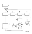
- FIG. 4 shows a block diagram of an excitation electronics according to the invention.
- the voltage supply 12 an on-off switch, 13 the burst and frequency generation, 14 the pre-stage, 15 the final stage, 16 the transmitter, 3 the ultrasonic liquid atomizer, 2 an temperature-dependent resistance, with 17 the power supply, with 18 and 19 the measured value coil I and II, with 20 the measured value comparator and with 22 the frequency control.
- the ultrasonic liquid atomizer 3 is excited via a preliminary and final stage with a burst, the burst frequency of which can be regulated by the method according to the invention.
- the regulation takes place via a current measurement at different times and a comparison of different currents.
- a temperature-dependent resistor 2 is attached to the ultrasonic atomizer 3.
- the electronics are switched off by the temperature-dependent resistor 2 at impermissible temperatures.
- FIG. 5 shows the ultrasonic liquid atomizer with a piezoceramic 4, the coupled amplitude transformer 5 and the atomizing plate 6.
- the tube 7 integrated in the atomizer cone serves to supply liquid. 8 is the excitation electronics.
Landscapes
- Engineering & Computer Science (AREA)
- Mechanical Engineering (AREA)
- Special Spraying Apparatus (AREA)
- Apparatuses For Generation Of Mechanical Vibrations (AREA)
Abstract
Description
Die Erfindung betrifft ein Verfahren nach dem Oberbegriff des Patentanspruches 1.The invention relates to a method according to the preamble of
Es ist ein Verfahren zum Betrieb eines Ultraschallschwingers zur Flüssigkeitszerstäubung bekannt, wobei die elektrische Leistung zeitlich getaktet zugeführt wird und die zugeführte Leistung im Mittel für die eingestellte Flüssigkeitsmenge ausreichend ist, während die jeweilige Spitzenleistung so hoch bemessen ist, daß eine kurzfristig an Flüssigkeit zuviel zugeführte Menge abgeschüttelt werden kann (DE-OS 33 14 609). Zum Betrieb von Ultraschallflüssigkeitszerstäubern ist der Ultraschallschwinger manuell auf seine Grundbetriebsfrequenz abzustimmen und es lassen sich die mit Fertigungstoleranzen behafteten Ultraschallzerstäuber, die beispielsweise unterschiedliche Arbeitsfrequenzen aufweisen, nicht ohne Abgleich austauschen.A method for operating an ultrasonic oscillator for liquid atomization is known, the electrical power being supplied in a timed manner and the power supplied being sufficient on average for the amount of liquid set, while the respective peak power is so high that a short supply of liquid is too short can be shaken off (DE-OS 33 14 609). To operate ultrasonic liquid atomizers, the ultrasonic oscillator must be manually adjusted to its basic operating frequency, and the ultrasonic atomizers, which have manufacturing tolerances and which have different working frequencies, for example, cannot be exchanged without adjustment.
Weitere Verfahren erlauben zwar einen Betrieb mit automatischem Frequenzabgleich jedoch ohne eine zeitlich getaktete elektrische Leistung und nur mit mangelhafter Betriebssicherheit hinsichtlich der Abschüttlung eines Flüssigkeitstropfens und/oder bestimmten Betriebspunktes. Ferner können bei den bekannten Ausführungen bei Änderungen der Umgebungstemperatur sowie der Schwingertemperatur durch Eigenerwärmung diese Schaltungen aufgrund ihrer geringen Nachstimmbandbreite keinen sicheren Zerstäuberbetrieb garantieren.Although other methods allow operation with automatic frequency adjustment, however, they do not have a timed electrical output and only with inadequate operational reliability with regard to the discharge of a liquid drop and / or a certain operating point. Furthermore, in the known designs, when the ambient temperature and the oscillator temperature change due to self-heating, these circuits cannot guarantee reliable atomizer operation due to their small tuning range.
Aufgabe der Erfindung ist es einen Ultraschallflüssigkeitszerstäuber zu konzipieren, der eine sichere Zerstäubung mit kontinuierlich automatischer Frequenznachstimmung und automatischer Abschüttlung eines überflutenden Zerstäubertellers ermöglicht. Ferner sollen eine geringe Leistungsaufnahme der Elektronik, eine niedrige Temperaturbelastung und eine hohe Zerstäubungsrate gewährleistet werden. Eine automatische Temperaturüberwachung soll integriert sein.The object of the invention is to design an ultrasonic liquid atomizer which enables reliable atomization with continuously automatic frequency adjustment and automatic shaking off of a flooding atomizing plate. Furthermore, a low power consumption of the electronics, a low temperature load and a high atomization rate should be guaranteed. Automatic temperature monitoring should be integrated.
Diese Aufgabe wird mit einem Verfahren nach dem Oberbegriff des Patentanspruches 1 erfindungsgemäß mit Hilfe der Merkmale des Kennzeichens des Patentanspruches 1 gelöst. Weitere Ausgestaltungen und Weiterbildungen gehen aus den Unteransprüchen hervor.This object is achieved with a method according to the preamble of
Bei Durchführung des erfindungsgemäßen Verfahrens werden eine sichere Zerstäubung bei geringer Leistungsaufnahme der Elektronik und eine niedrigere Temperaturbelastung des Ultraschallzerstäubers erreicht. Es wird ein schnelles Finden der optimalen Arbeitsfrequenz des Ultraschallzerstäubers erreicht, da nur ein vorgegebener Frequenzbereich, in dem die Arbeitsfrequenz des Ultraschallflüssigkeitszerstäubers liegt, durchlaufen werden muß. Ferner wird die Betriebssicherheit erhöht, da ein Einrasten auf einer anderen Frequenz, z.B. der Verbundresonanzfrequenz des Ultraschallzerstäubers, was zur Zerstörung des Ultraschallzerstäubers führen würde, bei der erfindungsgemäßen Ausführung nicht eintritt.When the method according to the invention is carried out, reliable atomization with low power consumption of the electronics and a lower temperature load on the ultrasonic atomizer are achieved. The optimum working frequency of the ultrasonic atomizer is found quickly since only a predetermined frequency range in which the working frequency of the ultrasonic liquid atomizer lies has to be run through. Furthermore, the operational safety is increased, since a snapping on a different frequency, e.g. the compound resonance frequency of the ultrasonic atomizer, which would lead to the destruction of the ultrasonic atomizer, does not occur in the embodiment according to the invention.
Der Ultraschallzerstäuber wird mit einem Burst angeregt, dessen Impulsdauer t₁ beträgt. Er schwingt mit der Zeit dauer t₂ frei aus, bevor der nächste Burst folgt (FIG 3). Mit einer Strommeßschaltung wird der Strom durch die Endstufe proportional dem Strom durch den Ultraschallzerstäuber erfaßt und in eine Spannung umgesetzt - siehe FIG 1. Um Fehlmessungen, beispielsweise durch Einschwingvorgänge zu vermeiden, wird ein Teil t₃ des stromportionalen Signals ausgeblendet und danach für kurze Zeit der Strom t₄ gemessen und dieser Wert in einem Meßwertspeicher abgelegt (FIG 1, FIG 3 und FIG 4).The ultrasonic atomizer is excited with a burst whose pulse duration is
In der Pause zwischen zwei Burstsignalen t₂ wird dieser Meßwert von Speicher I in Speicher II (FIG 4) übergeben. Bei dem auf diese Pause folgenden Burst t₁ wird der dann vom Meßwertspeicher I neu aufgenommene Strommeßwert durch einen Vergleicher mit dem im Meßwertspeicher II abgelegten, vorhergehenden Strommeßwert verglichen (FIG 4).In the pause between two burst signals t₂ this measured value is transferred from memory I to memory II (FIG. 4). In the
Ist die Differenz der im Meßwertspeicher II und Meßwertspeicher I stehenden Strommeßwerte kleiner als der eingestellte untere Schwellwert, so wird die Frequenz um jeweils einen Schritt pro Burst erhöht. Dies kann der Fall sein bei der Inbetriebnahme der Schaltung, wenn die optimale Betriebsfrequenz gesucht wird.If the difference between the current measured values in the measured value memory II and the measured value memory I is smaller than the set lower threshold value, the frequency is increased by one step per burst. This can be the case when the circuit is started up when the optimum operating frequency is sought.
Ist die Differenz der Strommeßwerte größer als der eingestellte obere Schwellwert, so wird die Frequenz um einen Schritt pro Burst erniedrigt.If the difference between the current measurement values is greater than the set upper threshold value, the frequency is reduced by one step per burst.
Liegt die Differenz der Strommeßwerte innerhalb des Schwellwertbereiches, so wird die Frequenzsuchrichtung beibehalten, die beim vorhergehenden Burst maßgebend war.If the difference between the current measured values lies within the threshold value range, the frequency search direction that was decisive for the previous burst is retained.
Um Arbeitsfrequenzänderungen des Ultraschallschwingers in Richtung tieferer Frequenz, hervorgerufen durch Änderungen der Umgebungstemperatur bzw. durch Eigenerwärmung, schneller ausregeln zu können, wird nach einer bestimmten Zeitdauer t₇ die Arbeitsfrequenz der Elektronik zwangsweise um einen Schritt erniedrigt (FIG 4).In order to be able to compensate for changes in the working frequency of the ultrasonic vibrator in the direction of a lower frequency, caused by changes in the ambient temperature or by self-heating, the working frequency of the electronics is forcibly reduced by one step after a certain period of time t₇ (FIG. 4).
Die Erfindung ist durch die Abhängigkeit des Stromes durch die Endstufe (proportional dem Strom durch den Ultraschallschwinger) nach Aufbereitung durch die Elektronik in Abhängigkeit von der Frequenz veranschaulicht. FIG 2 zeigt besonders deutlich den erfindungsgemäßen Effekt, wonach die Arbeitsfrequenz des Ultraschallzerstäubers sehr schnell gefunden werden kann und es keine Rolle spielt, ob dieser gedämpft (überfluteter Zerstäuberteller) oder frei schwingt. Die Suchrichtung geht dabei von tiefen zu hohen Frequenzen. Ferner geht der Übergang des Zerstäubers vom stark gedämpften (überfluteten) in den schwach bedämpften (zerstäubenden) Zustand - verbunden mit einer Erhöhung der Arbeitsfrequenz des Ultraschallzerstäubers - ebenfalls sehr schnell vonstatten. Ein weiterer Vorteil ist, daß nach dem Finden der optimalen Zerstäuberarbeitsfrequenz die Schaltung eng um den optimalen Arbeitspunkt pendelt. In den Bereichen "A" außerhalb der optimalen Arbeitspunkte wird durch entsprechende Schaltungsmaßnahmen ein konstanter Strommeßwert vorgegeben, damit die Schaltung schnell auf der Arbeitsfrequenz des Ultraschallzerstäubers einrasten kann.The invention is illustrated by the dependence of the current through the output stage (proportional to the current through the ultrasonic oscillator) after processing by the electronics as a function of the frequency. 2 shows particularly clearly the effect according to the invention, according to which the working frequency of the ultrasonic atomizer can be found very quickly and it does not matter whether it is damped (flooded atomizing plate) or vibrates freely. The search direction goes from low to high frequencies. Furthermore, the transition of the atomizer from the strongly damped (flooded) to the weakly damped (atomizing) state - combined with an increase in the working frequency of the ultrasonic atomizer - also takes place very quickly. Another advantage is that after finding the optimal atomizer operating frequency, the circuit oscillates closely around the optimal operating point. In areas "A" outside of the optimal operating points, a constant current measurement value is specified by appropriate circuit measures so that the circuit can snap into place at the operating frequency of the ultrasonic atomizer.
Das erfindungsgemäße Verfahren eignet sich besonders zum Betrieb eines piezoelektrischen Ultraschallzerstäubers mit einer Piezokeramik und einem Amplituden transformator mit einem Zerstäuberteller (siehe FIG 5). Um eine Zerstörung des Ultraschallflüssigkeitszerstäubers durch Übertemperatur zu vermeiden, beispielsweise durch Trockenlaufen, ist es vorteilhaft auf die Keramik des Ultraschallzerstäubers einen temperaturabhängigen Widerstand aufzubringen (FIG 6). Falls z.B. durch Trockenlaufen eine unzulässig hohe Temperatur am Ultraschallzerstäuber entstehen würde, schaltet die Elektronik die Endstufe solange ab, bis der Ultraschallzerstäuber wieder auf zulässige Temperaturen abgekühlt ist.The method according to the invention is particularly suitable for operating a piezoelectric ultrasonic atomizer with a piezoceramic and an amplitude transformer with an atomizing plate (see FIG. 5). In order to avoid destruction of the ultrasonic liquid atomizer by excess temperature, for example by running dry, it is advantageous to apply a temperature-dependent resistor to the ceramic of the ultrasonic atomizer (FIG. 6). If, for example, an impermissibly high temperature would occur on the ultrasonic atomizer as a result of running dry, the electronics switch off the output stage until the ultrasonic atomizer has cooled down again to permissible temperatures.
Nach dem erfindungsgemäßen Verfahren arbeitende Ultraschallflüssigkeitszerstäuber sind besonders geeignet für die Zerstäubung von Kraftstoff, wie Dieselöl, Benzin, für Brenner, Motoren, Generatoren und Standheizungen, für Kosmetika, wie Haarspray, Deodorants und Parfüms, für Reinigungsmittel, Medikamente zu Inhalationszwecken, Lösungsmitteln und Wasser, beispielsweise in Luftbefeuchter, Kleinklimakammern, Klimaanlagen und Terrarien sowie für den Einsatz in Anlagen zur Beschichtung, Befeuchtung und Klimatisierung. Das erfindungsgemäße Verfahren wird mit besonderem Vorteil eingesetzt zum Betrieb eines piezoelektrischen Ultraschallzerstäubers mit einer Piezokeramik und einem Amplitudentransformator mit einem Zerstäuberteller und Anregungselektronik.Ultrasonic liquid atomizers working according to the method according to the invention are particularly suitable for atomizing fuel, such as diesel oil, gasoline, for burners, engines, generators and auxiliary heaters, for cosmetics, such as hairspray, deodorants and perfumes, for cleaning agents, medications for inhalation purposes, solvents and water, For example in humidifiers, small climate chambers, air conditioning systems and terrariums as well as for use in systems for coating, humidification and air conditioning. The method according to the invention is used with particular advantage to operate a piezoelectric ultrasonic atomizer with a piezoceramic and an amplitude transformer with an atomizing plate and excitation electronics.
Zur näheren Erläuterung der Erfindung wird auf die Zeichnung verwiesen. Es zeigen
- FIG 1 ein Diagramm des Stromverlaufs nach der Aufbereitung durch die Elektronik.
- FIG 2 ein Diagramm für die Abhängigkeit des Stromes durch die Endstufe.
- FIG 3 die zeitliche Signalfolge in der Elektronik.
- FIG 4 ein Blockschaltbild für die Elektronik.
- FIG 5 einen Ultraschallflüssigkeitszerstäuber im Schnitt.
- FIG 6 einen auf einen Ultraschallflüssigkeitszerstäuber im Schnitt mit aufgebrachtem temperaturabhängigen Widerstand.
- 1 shows a diagram of the current profile after processing by the electronics.
- 2 shows a diagram for the dependence of the current through the output stage.
- 3 shows the temporal signal sequence in the electronics.
- 4 shows a block diagram for the electronics.
- 5 shows an ultrasonic liquid atomizer in section.
- 6 shows a section of an ultrasonic liquid atomizer with an applied temperature-dependent resistor.
In FIG 1 ist auf der Ordinate der durch den Strom verursachte Spannungsabfall aufgetragen, während auf der Abszisse die Zeit dargestellt ist. Während der Zeitdauer t₃ findet keine Messung statt. Gemessen wird während der Zeitdauer t₄ . Die Zeitdauer des Burstsignals ist t₁ .In FIG. 1, the voltage drop caused by the current is plotted on the ordinate, while time is shown on the abscissa. No measurement takes place during the period t₃. The measurement is made during the period t₄. The duration of the burst signal is t₁.
In FIG 2 ist auf der Ordinate der Spannungsabfall an einem Widerstand, verursacht durch den Strom durch die Endstufe dargestellt, während auf der Abszisse die Frequenz aufgetragen ist, wobei f₁ die Frequenz bzw. der Arbeitspunkt des mit Flüssigkeit überfluteten bzw. bedämpften Flüssigkeitszerstäubers ist, während f₂ der Arbeitspunkt bzw. die Frequenz des unbedämpften Flüssigkeitszerstäubers ist. Der Bereich A stellt den nicht für die Zerstäubung nutzbaren Frequenzbereich dar.In Figure 2, the ordinate of the voltage drop across a resistor caused by the current through the output stage is shown, while the frequency is plotted on the abscissa, where f₁ is the frequency or the operating point of the liquid atomizer flooded or damped while f₂ is the operating point or the frequency of the undamped liquid atomizer. Area A represents the frequency range that cannot be used for atomization.
In FIG 3 ist die genaue Schaltungsbeschreibung aufgetragen, wobei a die Zeitdauer t₁ für die Einschaltzeit und t₂ die Zeitdauer für die Ausschaltzeit des Burstimpulses darstellen. In b ist die Verzögerungszeitdauer t₃, während der nicht gemessen wird, eingezeichnet. c stellt die im Anschluß nach t₃ folgende Strommeßzeit t₄ dar. In d und e ist die Übernahme des Meßwertes des Stromes vom Meßwertspeicher I nach dem Meßwertspeicher II dargestellt. Die Zeit t₅ der Zählimpulse folgt im Anschluß an das Burstsignal. Nach Abschluß von t₅ erfolgt die Meßwertübernahme vom Meßwertspeicher I nach Meßwertspeicher II innerhalb der Zeit t₆.In Figure 3, the exact circuit description is plotted, with a representing the
In FIG 4 ist ein Blockschaltbild einer Anregungselektronik gemäß der Erfindung dargestellt. In diesem sind mit 1 die Spannungsversorgung, mit 12 ein Ein-Aus-Schalter, mit 13 die Burst- und Frequenzerzeugung, mit 14 die Vorstufe, mit 15 die Endstufe, mit 16 der Übertrager, mit 3 der Ultraschall-Flüssigkeitszerstäuber, mit 2 ein temperaturabhängiger Widerstand, mit 17 die Stromversorgung, mit 18 und 19 die Meßwertspule I und II, mit 20 der Meßwertvergleicher und mit 22 die Frequenzsteuerung dargestellt. Es ist zu erkennen, daß der Ultraschallflüssigkeitszerstäuber 3 über eine Vor- und Endstufe mit einem Burst angeregt wird, dessen Burstfrequenz nach dem erfindungsgemäßen Verfahren regelbar ist. Die Regelung findet über eine Strommessung zu verschiedenen Zeitpunkten und einem Vergleich von verschiedenen Strömen statt.4 shows a block diagram of an excitation electronics according to the invention. In this there are 1 the voltage supply, 12 an on-off switch, 13 the burst and frequency generation, 14 the pre-stage, 15 the final stage, 16 the transmitter, 3 the ultrasonic liquid atomizer, 2 an temperature-dependent resistance, with 17 the power supply, with 18 and 19 the measured value coil I and II, with 20 the measured value comparator and with 22 the frequency control. It can be seen that the ultrasonic liquid atomizer 3 is excited via a preliminary and final stage with a burst, the burst frequency of which can be regulated by the method according to the invention. The regulation takes place via a current measurement at different times and a comparison of different currents.
Zum Schutz des Zerstäuberkegels für Übertemperaturen ist ein temperaturabhängiger Widerstand 2 auf dem Ultraschallzerstäuber 3 angebracht. Durch den temperaturabhängigen Widerstand 2 wird bei unzulässigen Temperaturen die Elektronik abgeschaltet.To protect the atomizer cone for excess temperatures, a temperature-dependent resistor 2 is attached to the ultrasonic atomizer 3. The electronics are switched off by the temperature-dependent resistor 2 at impermissible temperatures.
In FIG 5 ist der Ultraschallflüssigkeitszerstäuber mit einer Piezokeramik 4, dem angekoppelten Amplitudentransformator 5 und dem Zerstäuberteller 6 dargestellt. Das im Zerstäuberkegel integrierte Röhrchen 7 dient zur Flüssigkeitszufuhr. 8 ist die Anregungselektronik.5 shows the ultrasonic liquid atomizer with a piezoceramic 4, the coupled amplitude transformer 5 and the
FIG 6 zeigt einen auf eine Piezokeramik 9 aufgebrachten temperaturabhängigen Widerstand 10. 11 ist die Anregungselektronik.6 shows a temperature-
Claims (11)
Priority Applications (1)
| Application Number | Priority Date | Filing Date | Title |
|---|---|---|---|
| AT86112865T ATE68111T1 (en) | 1985-09-30 | 1986-09-17 | METHOD OF OPERATING AN ULTRASONIC ATOMIZER FOR LIQUID ATOMIZATION. |
Applications Claiming Priority (2)
| Application Number | Priority Date | Filing Date | Title |
|---|---|---|---|
| DE3534853 | 1985-09-30 | ||
| DE19853534853 DE3534853A1 (en) | 1985-09-30 | 1985-09-30 | METHOD FOR OPERATING AN ULTRASONIC SPRAYER FOR LIQUID SPRAYING |
Publications (2)
| Publication Number | Publication Date |
|---|---|
| EP0219693A1 true EP0219693A1 (en) | 1987-04-29 |
| EP0219693B1 EP0219693B1 (en) | 1991-10-09 |
Family
ID=6282366
Family Applications (1)
| Application Number | Title | Priority Date | Filing Date |
|---|---|---|---|
| EP86112865A Expired - Lifetime EP0219693B1 (en) | 1985-09-30 | 1986-09-17 | Method for operating a fluid-atomising ultrasonic atomiser |
Country Status (4)
| Country | Link |
|---|---|
| US (1) | US4689515A (en) |
| EP (1) | EP0219693B1 (en) |
| AT (1) | ATE68111T1 (en) |
| DE (2) | DE3534853A1 (en) |
Cited By (2)
| Publication number | Priority date | Publication date | Assignee | Title |
|---|---|---|---|---|
| WO1996000132A2 (en) * | 1994-06-23 | 1996-01-04 | J.E.M. Smoke Machine Co. Ltd. | A method of creating an effect |
| EP1875969A1 (en) * | 2006-07-07 | 2008-01-09 | L'oreal | Generator for exciting a piezoelectric transducer |
Families Citing this family (38)
| Publication number | Priority date | Publication date | Assignee | Title |
|---|---|---|---|---|
| JPS60222552A (en) * | 1984-04-19 | 1985-11-07 | Toa Nenryo Kogyo Kk | Ultrasonic injection method and injection valve |
| JPS6338193A (en) * | 1986-08-01 | 1988-02-18 | Toa Nenryo Kogyo Kk | Ultrasonic vibrator horn |
| US4799622A (en) * | 1986-08-05 | 1989-01-24 | Tao Nenryo Kogyo Kabushiki Kaisha | Ultrasonic atomizing apparatus |
| KR900007413B1 (en) * | 1986-08-26 | 1990-10-08 | 마쯔시다덴기산교 가부시기가이샤 | Drive method for ultrasonic motor |
| CH672894A5 (en) * | 1987-09-14 | 1990-01-15 | Undatim Ultrasonics | |
| US4966131A (en) * | 1988-02-09 | 1990-10-30 | Mettler Electronics Corp. | Ultrasound power generating system with sampled-data frequency control |
| US5095890A (en) * | 1988-02-09 | 1992-03-17 | Mettler Electronics Corp. | Method for sampled data frequency control of an ultrasound power generating system |
| US5113116A (en) * | 1989-10-05 | 1992-05-12 | Firma J. Eberspacher | Circuit arrangement for accurately and effectively driving an ultrasonic transducer |
| JPH03161083A (en) * | 1989-11-17 | 1991-07-11 | Aisin Seiki Co Ltd | Driving mechanism for piezoelectric vibrator and water drop removing device using same driving mechanism |
| GB9226474D0 (en) * | 1992-12-18 | 1993-02-10 | Ici Plc | Production of particulate materials |
| US5387180A (en) * | 1993-05-20 | 1995-02-07 | Allergan, Inc. | Ultrasonic frequency synthesizer for phaco surgery |
| DE4412900C2 (en) * | 1994-04-14 | 2000-04-27 | Eberspaecher J Gmbh & Co | Method and device for determining the onset of a flood of an ultrasonic atomizer |
| US5560543A (en) * | 1994-09-19 | 1996-10-01 | Board Of Regents, The University Of Texas System | Heat-resistant broad-bandwidth liquid droplet generators |
| US5568003A (en) * | 1994-09-28 | 1996-10-22 | Zygo Corporation | Method and apparatus for producing repeatable motion from biased piezoelectric transducers |
| WO1996028205A1 (en) * | 1995-03-14 | 1996-09-19 | Siemens Aktiengesellschaft | Ultrasonic atomizer device with removable precision dosing unit |
| CA2215331C (en) * | 1995-03-14 | 2002-01-22 | Siemens Aktiengesellschaft | Ultrasonic atomizer device with removable precision dosating unit |
| ES2209857T3 (en) | 1999-03-05 | 2004-07-01 | S. C. JOHNSON & SON, INC. | CONTROL SYSTEM FOR SPRAYING LIQUIDS WITH A PIEZOELECTRIC VIBRATOR. |
| DE19916161B4 (en) * | 1999-04-11 | 2008-06-05 | Dürr Dental GmbH & Co. KG | Device for generating high-frequency mechanical oscillations for a dental handpiece |
| FR2802118A1 (en) * | 1999-12-10 | 2001-06-15 | Touzova Tamara | METHOD AND VIBRATORY DEVICE FOR CONDITIONING, AIR CONDITIONING, COOLING AND DECONTAMINATION, DISINFECTION, STERILIZATION OF PHYSICAL MEDIA |
| US7077853B2 (en) * | 2000-10-20 | 2006-07-18 | Ethicon Endo-Surgery, Inc. | Method for calculating transducer capacitance to determine transducer temperature |
| WO2003098971A1 (en) | 2002-05-13 | 2003-11-27 | S.C. Johnson & Son, Inc. | Coordinated emission of fragrance, light, and sound |
| EP2384771B1 (en) | 2003-02-07 | 2013-01-23 | S.C.Johnson & Son, Inc. | Diffuser with light emitting diode nightlight |
| US7645300B2 (en) | 2004-02-02 | 2010-01-12 | Visiogen, Inc. | Injector for intraocular lens system |
| DE202005003298U1 (en) * | 2005-03-02 | 2006-07-13 | Argillon Gmbh | ultrasonic nebulizer |
| US7281811B2 (en) | 2005-03-31 | 2007-10-16 | S. C. Johnson & Son, Inc. | Multi-clarity lenses |
| US7643734B2 (en) | 2005-03-31 | 2010-01-05 | S.C. Johnson & Son, Inc. | Bottle eject mechanism |
| US7589340B2 (en) | 2005-03-31 | 2009-09-15 | S.C. Johnson & Son, Inc. | System for detecting a container or contents of the container |
| US9339836B2 (en) * | 2005-05-23 | 2016-05-17 | Biosonic Australia Pty Ltd | Ultrasonic atomization apparatus |
| WO2009155245A1 (en) * | 2008-06-17 | 2009-12-23 | Davicon Corporation | Liquid dispensing apparatus using a passive liquid metering method |
| IT1393824B1 (en) * | 2009-04-20 | 2012-05-11 | Zobele Holding Spa | LIQUID ATOMIZER WITH PIEZOELECTRIC VIBRATION DEVICE WITH IMPROVED ELECTRONIC CONTROL CIRCUIT AND RELATED DRIVING METHOD. |
| ES2614917T3 (en) * | 2009-07-17 | 2017-06-02 | Nektar Therapeutics | Systems and methods for propulsion in sealed nebulizers |
| JP5429993B2 (en) * | 2010-03-04 | 2014-02-26 | 国立大学法人東京工業大学 | Odor generator |
| WO2013072863A1 (en) * | 2011-11-15 | 2013-05-23 | Koninklijke Philips Electronics N.V. | A nebulizer, a control unit for controlling the same and a method of operating a nebulizer |
| EP2796208A1 (en) * | 2013-04-22 | 2014-10-29 | Ipratech SA | Method for controlling an acoustic cell |
| WO2015025290A1 (en) * | 2013-08-23 | 2015-02-26 | Koninklijke Philips N.V. | Controlling a medication nebulizer through a smartphone |
| US12052925B2 (en) | 2016-01-23 | 2024-07-30 | Liat Keng KANG | Method and device for driving a piezoelectric device |
| CN112583395B (en) * | 2020-12-03 | 2023-03-28 | 成都动芯微电子有限公司 | Ultrasonic atomization sheet frequency tracking system and method |
| CN115363282A (en) * | 2021-05-21 | 2022-11-22 | 深圳市合元科技有限公司 | Electronic atomization device and control method |
Citations (6)
| Publication number | Priority date | Publication date | Assignee | Title |
|---|---|---|---|---|
| DE1240316B (en) * | 1962-03-30 | 1967-05-11 | Aeroprojects Inc | Device for tracking the frequency of an ultrasonic generator in the event of temperature fluctuations |
| US3842340A (en) * | 1969-02-20 | 1974-10-15 | Philips Corp | Generator for producing ultrasonic oscillations |
| FR2421513A1 (en) * | 1978-03-31 | 1979-10-26 | Gaboriaud Paul | ULTRA-SONIC ATOMIZER WITH AUTOMATIC CONTROL |
| US4275363A (en) * | 1979-07-06 | 1981-06-23 | Taga Electric Co., Ltd. | Method of and apparatus for driving an ultrasonic transducer including a phase locked loop and a sweep circuit |
| EP0123277A2 (en) * | 1983-04-22 | 1984-10-31 | Siemens Aktiengesellschaft | Method of driving an ultrasonic oscillator for an atomizing fluid |
| US4578650A (en) * | 1983-06-15 | 1986-03-25 | Watson Industries, Inc. | Resonance drive oscillator circuit |
Family Cites Families (4)
| Publication number | Priority date | Publication date | Assignee | Title |
|---|---|---|---|---|
| US3889166A (en) * | 1974-01-15 | 1975-06-10 | Quintron Inc | Automatic frequency control for a sandwich transducer using voltage feedback |
| DE2721225C2 (en) * | 1977-05-11 | 1981-10-29 | Siemens AG, 1000 Berlin und 8000 München | Circuit arrangement for frequency self-control of an ultrasonic transmitter transducer |
| SU760246A1 (en) * | 1978-05-16 | 1980-08-30 | Le Polt I Im M I Kalinina | Method and device for phase control in piezosemiconductor transformer |
| DE3222425A1 (en) * | 1982-06-15 | 1983-12-22 | Licentia Patent-Verwaltungs-Gmbh, 6000 Frankfurt | Generator for driving a piezo resonator |
-
1985
- 1985-09-30 DE DE19853534853 patent/DE3534853A1/en not_active Withdrawn
-
1986
- 1986-09-17 AT AT86112865T patent/ATE68111T1/en not_active IP Right Cessation
- 1986-09-17 DE DE8686112865T patent/DE3681871D1/en not_active Expired - Fee Related
- 1986-09-17 EP EP86112865A patent/EP0219693B1/en not_active Expired - Lifetime
- 1986-09-24 US US06/910,959 patent/US4689515A/en not_active Expired - Fee Related
Patent Citations (6)
| Publication number | Priority date | Publication date | Assignee | Title |
|---|---|---|---|---|
| DE1240316B (en) * | 1962-03-30 | 1967-05-11 | Aeroprojects Inc | Device for tracking the frequency of an ultrasonic generator in the event of temperature fluctuations |
| US3842340A (en) * | 1969-02-20 | 1974-10-15 | Philips Corp | Generator for producing ultrasonic oscillations |
| FR2421513A1 (en) * | 1978-03-31 | 1979-10-26 | Gaboriaud Paul | ULTRA-SONIC ATOMIZER WITH AUTOMATIC CONTROL |
| US4275363A (en) * | 1979-07-06 | 1981-06-23 | Taga Electric Co., Ltd. | Method of and apparatus for driving an ultrasonic transducer including a phase locked loop and a sweep circuit |
| EP0123277A2 (en) * | 1983-04-22 | 1984-10-31 | Siemens Aktiengesellschaft | Method of driving an ultrasonic oscillator for an atomizing fluid |
| US4578650A (en) * | 1983-06-15 | 1986-03-25 | Watson Industries, Inc. | Resonance drive oscillator circuit |
Cited By (5)
| Publication number | Priority date | Publication date | Assignee | Title |
|---|---|---|---|---|
| WO1996000132A2 (en) * | 1994-06-23 | 1996-01-04 | J.E.M. Smoke Machine Co. Ltd. | A method of creating an effect |
| WO1996000132A3 (en) * | 1994-06-23 | 1996-03-28 | Jem Smoke Machine Co | A method of creating an effect |
| EP1875969A1 (en) * | 2006-07-07 | 2008-01-09 | L'oreal | Generator for exciting a piezoelectric transducer |
| FR2903331A1 (en) * | 2006-07-07 | 2008-01-11 | Oreal | GENERATOR FOR EXCITING A PIEZOELECTRIC TRANSDUCER |
| US7960894B2 (en) | 2006-07-07 | 2011-06-14 | L'oreal S.A. | Generator for exciting piezoelectric transducer |
Also Published As
| Publication number | Publication date |
|---|---|
| US4689515A (en) | 1987-08-25 |
| DE3534853A1 (en) | 1987-04-02 |
| DE3681871D1 (en) | 1991-11-14 |
| ATE68111T1 (en) | 1991-10-15 |
| EP0219693B1 (en) | 1991-10-09 |
Similar Documents
| Publication | Publication Date | Title |
|---|---|---|
| EP0219693A1 (en) | Method for operating a fluid-atomising ultrasonic atomiser | |
| DE3686574T2 (en) | DEVICE FOR SPRAYING FUEL THROUGH ULTRASONIC FOR INTERNAL COMBUSTION ENGINES. | |
| DE4106564C2 (en) | Device for the electrostatic atomization of liquids | |
| EP0213283A1 (en) | Coin testing apparatus | |
| DE2144892B2 (en) | DEVICE FOR GENERATING A DROP JET, IN PARTICULAR FOR INK DROP PENS | |
| EP0219725A1 (en) | Method of compensating interference voltages in the electrode circuit in magnetic-inductive flow measurement | |
| DE19814594A1 (en) | Charging and discharging piezoelectric element to desired voltage | |
| DE19626101B4 (en) | Circuit arrangement for starting and operating a high-pressure discharge lamp | |
| DE3708210A1 (en) | CIRCUIT ARRANGEMENT FOR EVALUATING THE SIGNALS OF AN INDUCTIVE MEASURING VALUE | |
| DE2916540C2 (en) | Electrical circuit arrangement for controlling a piezoelectric transducer | |
| EP0340470A1 (en) | Method and circuit for driving an ultrasonic transducer, and their use in atomizing a liquid | |
| DE2604446A1 (en) | DEVICE FOR CONTROLLING THE ELECTRONIC FUEL INJECTION FOR A COMBUSTION ENGINE | |
| DE19646917A1 (en) | Ignition monitor for IC engine | |
| DE4036618C3 (en) | Device for driving a piezoelectric vibrator | |
| DE3431481A1 (en) | Method for operating ultrasound power oscillators, especially in apparatuses for tartar removal | |
| EP0303944A1 (en) | Method and circuit for the excitation of an ultrasonic vibrator and their use in the atomisation of a liquid | |
| WO1989002826A1 (en) | Process and device for monitoring droplet ejection from ejection nozzles of ink-printing heads | |
| DE3314609A1 (en) | METHOD FOR OPERATING AN ULTRASONIC VIBRATOR FOR LIQUID SPRAYING | |
| AT413867B (en) | CAPACITIVE DISCHARGING IGNITION SYSTEM FOR A COMBUSTION ENGINE | |
| DE3216186A1 (en) | LASER ARRANGEMENT | |
| DE4244761C2 (en) | Level limit switch | |
| DE2444511A1 (en) | Flow velocity meter especially for induction gases - is for internal combustion engine and uses sensitive resistor element in bridge circuit | |
| DE602004011669T2 (en) | POWER SUPPLY | |
| EP0652362A1 (en) | Method and device for reducing the consumption of fossil free-flowing fuels | |
| DE2738558A1 (en) | CIRCUIT ARRANGEMENT FOR MEASURING CURRENTS AT HIGH POTENTIAL |
Legal Events
| Date | Code | Title | Description |
|---|---|---|---|
| PUAI | Public reference made under article 153(3) epc to a published international application that has entered the european phase |
Free format text: ORIGINAL CODE: 0009012 |
|
| AK | Designated contracting states |
Kind code of ref document: A1 Designated state(s): AT BE CH DE FR GB IT LI NL SE |
|
| 17P | Request for examination filed |
Effective date: 19870826 |
|
| 17Q | First examination report despatched |
Effective date: 19890714 |
|
| GRAA | (expected) grant |
Free format text: ORIGINAL CODE: 0009210 |
|
| AK | Designated contracting states |
Kind code of ref document: B1 Designated state(s): AT BE CH DE FR GB IT LI NL SE |
|
| REF | Corresponds to: |
Ref document number: 68111 Country of ref document: AT Date of ref document: 19911015 Kind code of ref document: T |
|
| REF | Corresponds to: |
Ref document number: 3681871 Country of ref document: DE Date of ref document: 19911114 |
|
| ET | Fr: translation filed | ||
| ITF | It: translation for a ep patent filed | ||
| GBT | Gb: translation of ep patent filed (gb section 77(6)(a)/1977) | ||
| PLBE | No opposition filed within time limit |
Free format text: ORIGINAL CODE: 0009261 |
|
| STAA | Information on the status of an ep patent application or granted ep patent |
Free format text: STATUS: NO OPPOSITION FILED WITHIN TIME LIMIT |
|
| 26N | No opposition filed | ||
| PGFP | Annual fee paid to national office [announced via postgrant information from national office to epo] |
Ref country code: AT Payment date: 19930827 Year of fee payment: 8 |
|
| PGFP | Annual fee paid to national office [announced via postgrant information from national office to epo] |
Ref country code: BE Payment date: 19930920 Year of fee payment: 8 |
|
| PGFP | Annual fee paid to national office [announced via postgrant information from national office to epo] |
Ref country code: NL Payment date: 19930930 Year of fee payment: 8 |
|
| PGFP | Annual fee paid to national office [announced via postgrant information from national office to epo] |
Ref country code: CH Payment date: 19931215 Year of fee payment: 8 |
|
| PG25 | Lapsed in a contracting state [announced via postgrant information from national office to epo] |
Ref country code: AT Effective date: 19940917 |
|
| PG25 | Lapsed in a contracting state [announced via postgrant information from national office to epo] |
Ref country code: LI Effective date: 19940930 Ref country code: CH Effective date: 19940930 Ref country code: BE Effective date: 19940930 |
|
| EAL | Se: european patent in force in sweden |
Ref document number: 86112865.0 |
|
| BERE | Be: lapsed |
Owner name: SIEMENS A.G. Effective date: 19940930 |
|
| PG25 | Lapsed in a contracting state [announced via postgrant information from national office to epo] |
Ref country code: NL Effective date: 19950401 |
|
| NLV4 | Nl: lapsed or anulled due to non-payment of the annual fee | ||
| REG | Reference to a national code |
Ref country code: CH Ref legal event code: PL |
|
| PGFP | Annual fee paid to national office [announced via postgrant information from national office to epo] |
Ref country code: GB Payment date: 19960821 Year of fee payment: 11 |
|
| PGFP | Annual fee paid to national office [announced via postgrant information from national office to epo] |
Ref country code: SE Payment date: 19960912 Year of fee payment: 11 |
|
| PGFP | Annual fee paid to national office [announced via postgrant information from national office to epo] |
Ref country code: FR Payment date: 19960926 Year of fee payment: 11 |
|
| PGFP | Annual fee paid to national office [announced via postgrant information from national office to epo] |
Ref country code: DE Payment date: 19961118 Year of fee payment: 11 |
|
| PG25 | Lapsed in a contracting state [announced via postgrant information from national office to epo] |
Ref country code: GB Free format text: LAPSE BECAUSE OF NON-PAYMENT OF DUE FEES Effective date: 19970917 |
|
| PG25 | Lapsed in a contracting state [announced via postgrant information from national office to epo] |
Ref country code: SE Free format text: LAPSE BECAUSE OF NON-PAYMENT OF DUE FEES Effective date: 19970918 |
|
| PG25 | Lapsed in a contracting state [announced via postgrant information from national office to epo] |
Ref country code: FR Free format text: THE PATENT HAS BEEN ANNULLED BY A DECISION OF A NATIONAL AUTHORITY Effective date: 19970930 |
|
| GBPC | Gb: european patent ceased through non-payment of renewal fee |
Effective date: 19970917 |
|
| PG25 | Lapsed in a contracting state [announced via postgrant information from national office to epo] |
Ref country code: DE Free format text: LAPSE BECAUSE OF NON-PAYMENT OF DUE FEES Effective date: 19980603 |
|
| EUG | Se: european patent has lapsed |
Ref document number: 86112865.0 |
|
| REG | Reference to a national code |
Ref country code: FR Ref legal event code: ST |
|
| PG25 | Lapsed in a contracting state [announced via postgrant information from national office to epo] |
Ref country code: IT Free format text: LAPSE BECAUSE OF NON-PAYMENT OF DUE FEES;WARNING: LAPSES OF ITALIAN PATENTS WITH EFFECTIVE DATE BEFORE 2007 MAY HAVE OCCURRED AT ANY TIME BEFORE 2007. THE CORRECT EFFECTIVE DATE MAY BE DIFFERENT FROM THE ONE RECORDED. Effective date: 20050917 |