EP0219098A1 - Image signal regeneration device for an ultrasound image system and image device - Google Patents
Image signal regeneration device for an ultrasound image system and image device Download PDFInfo
- Publication number
- EP0219098A1 EP0219098A1 EP86114220A EP86114220A EP0219098A1 EP 0219098 A1 EP0219098 A1 EP 0219098A1 EP 86114220 A EP86114220 A EP 86114220A EP 86114220 A EP86114220 A EP 86114220A EP 0219098 A1 EP0219098 A1 EP 0219098A1
- Authority
- EP
- European Patent Office
- Prior art keywords
- filter
- value
- image
- values
- amplitude
- Prior art date
- Legal status (The legal status is an assumption and is not a legal conclusion. Google has not performed a legal analysis and makes no representation as to the accuracy of the status listed.)
- Granted
Links
Images


Classifications
-
- G—PHYSICS
- G01—MEASURING; TESTING
- G01S—RADIO DIRECTION-FINDING; RADIO NAVIGATION; DETERMINING DISTANCE OR VELOCITY BY USE OF RADIO WAVES; LOCATING OR PRESENCE-DETECTING BY USE OF THE REFLECTION OR RERADIATION OF RADIO WAVES; ANALOGOUS ARRANGEMENTS USING OTHER WAVES
- G01S7/00—Details of systems according to groups G01S13/00, G01S15/00, G01S17/00
- G01S7/52—Details of systems according to groups G01S13/00, G01S15/00, G01S17/00 of systems according to group G01S15/00
- G01S7/52017—Details of systems according to groups G01S13/00, G01S15/00, G01S17/00 of systems according to group G01S15/00 particularly adapted to short-range imaging
- G01S7/52053—Display arrangements
- G01S7/52057—Cathode ray tube displays
- G01S7/5206—Two-dimensional coordinated display of distance and direction; B-scan display
- G01S7/52065—Compound scan display, e.g. panoramic imaging
-
- G—PHYSICS
- G01—MEASURING; TESTING
- G01S—RADIO DIRECTION-FINDING; RADIO NAVIGATION; DETERMINING DISTANCE OR VELOCITY BY USE OF RADIO WAVES; LOCATING OR PRESENCE-DETECTING BY USE OF THE REFLECTION OR RERADIATION OF RADIO WAVES; ANALOGOUS ARRANGEMENTS USING OTHER WAVES
- G01S7/00—Details of systems according to groups G01S13/00, G01S15/00, G01S17/00
- G01S7/52—Details of systems according to groups G01S13/00, G01S15/00, G01S17/00 of systems according to group G01S15/00
- G01S7/52017—Details of systems according to groups G01S13/00, G01S15/00, G01S17/00 of systems according to group G01S15/00 particularly adapted to short-range imaging
- G01S7/52023—Details of receivers
- G01S7/52025—Details of receivers for pulse systems
- G01S7/52026—Extracting wanted echo signals
- G01S7/52028—Extracting wanted echo signals using digital techniques
-
- G—PHYSICS
- G01—MEASURING; TESTING
- G01S—RADIO DIRECTION-FINDING; RADIO NAVIGATION; DETERMINING DISTANCE OR VELOCITY BY USE OF RADIO WAVES; LOCATING OR PRESENCE-DETECTING BY USE OF THE REFLECTION OR RERADIATION OF RADIO WAVES; ANALOGOUS ARRANGEMENTS USING OTHER WAVES
- G01S7/00—Details of systems according to groups G01S13/00, G01S15/00, G01S17/00
- G01S7/52—Details of systems according to groups G01S13/00, G01S15/00, G01S17/00 of systems according to group G01S15/00
- G01S7/52017—Details of systems according to groups G01S13/00, G01S15/00, G01S17/00 of systems according to group G01S15/00 particularly adapted to short-range imaging
- G01S7/52077—Details of systems according to groups G01S13/00, G01S15/00, G01S17/00 of systems according to group G01S15/00 particularly adapted to short-range imaging with means for elimination of unwanted signals, e.g. noise or interference
-
- H—ELECTRICITY
- H03—ELECTRONIC CIRCUITRY
- H03H—IMPEDANCE NETWORKS, e.g. RESONANT CIRCUITS; RESONATORS
- H03H17/00—Networks using digital techniques
- H03H17/02—Frequency selective networks
- H03H17/04—Recursive filters
-
- H—ELECTRICITY
- H04—ELECTRIC COMMUNICATION TECHNIQUE
- H04N—PICTORIAL COMMUNICATION, e.g. TELEVISION
- H04N5/00—Details of television systems
- H04N5/14—Picture signal circuitry for video frequency region
- H04N5/21—Circuitry for suppressing or minimising disturbance, e.g. moiré or halo
Definitions
- the invention relates to a method for generating ultrasound cross-sectional images of a body, in which method a plurality of successive, at least partially overlapping, line-by-line scans of the body, carried out after the pulse echo method in a scanning plane, and image signals in digital form that generate the received echoes correspond, each scan comprising a predetermined number of scan lines and each of these a predetermined number of scan points, a predetermined time interval being provided between corresponding scan points of successive scans.
- the invention also relates to an image signal processing device that can be used to carry out the method according to the invention and an ultrasound imaging device that contains such a device.
- the object of the invention is therefore to remedy the disadvantage mentioned above.
- the image signal which corresponds in each case to one of the displayed pixels, is generated by a combination of image signals, the corresponding sampling points in succession Corresponds to scans, the combination of these image signals being carried out by time-discrete non-linear filtering thereof, each of the filter coefficients being variable as a function of the amplitude of the input signal of the filter.
- the invention also relates to an ultrasound imaging device for generating ultrasound cross-sectional images of a body, with which device a multiplicity of successive, at least partially overlapping, line-by-line scans of the body can be carried out according to the pulse echo method in order to image signals in digital form to generate, corresponding to the received echoes, each scan a predetermined number of scan lines and each of these comprises a predetermined number of scanning points, a predetermined time interval being provided between corresponding scanning points of successive scans, and which device comprises an ultrasound scanning device, a transmitter connected thereto, a receiver connected to the ultrasound scanning device, a television monitor connected to the receiver, and one with contains the control unit connected to the transmitter, the receiver, and the television monitor, wherein the receiver contains a detector circuit for generating an analog output signal.
- the device according to the invention is characterized in that it contains the image signal processing device described above.
- the advantages achieved by the invention are essentially to be seen in the fact that a considerable reduction in noise is achieved without movements in the area under examination causing the resulting resulting image to be blurred. It has now become possible to simultaneously produce easily recognizable ultrasound images of moving organs or parts of organs (e.g. heart valves) and to improve the quality of such images by reducing noise.
- the invention also has the advantage that its implementation requires a relatively low amount of circuitry.
- FIG 1 shows the block diagram of an ultrasound imaging device for carrying out the method according to the invention.
- a pulsed transmitter 15 controls an ultrasound transducer 10 of a scanning device 14 4 via a duplexer 14.
- This device is a mechanical sector scanner.
- the received echo signal passes through the duplexer l4 to the input of a receiver 26.
- the input of a depth compensation amplifier l6 is also the input of the receiver 26.
- the amplifier l6 is followed by a logarithmic amplifier l7 which supplies an output signal which is proportional over a certain range to the logarithm of the input signal.
- the exit of the loga rithmic amplifier l7 is connected via a line 29 to the input of a detector l8. With this detector, for example, absolute value formation and low-pass filtering of the output signal of the logarithmic amplifier 17 are carried out.
- the output signal of the detector 18 is output via a line 91.
- This signal is converted from analog to digital in the image signal processing device 27 using an analog / digital converter 19.
- the output signal of the converter 19 is fed via a bus line 3l to the input of a non-linear digital filter 2l.
- the output signal of the filter 2l is output via a bus line 36 and temporarily stored in an image memory / standard converter 22.
- the content of the image memory / standard converter 22 is read out.
- the signal read out is converted digitally to analog using a digital / analog converter 23.
- the output signal of the converter 23 is the output signal of the image signal processing device 27. This output signal is fed to a television monitor 24 as a television standard signal.
- the ultrasonic transducer l0 is moved by a motor l2 which is controlled by a motor control l3.
- the control electronics 25 shown give command and synchronization signals to all other blocks shown in FIG.
- the method according to the invention can also be used in ultrasound imaging in which the scanning patterns used only partially overlap.
- the method according to the invention can therefore also be carried out with the ultrasound device / image device shown in FIG. 2 by a block diagram, which works with an electronic compound scanner.
- the ultrasound imaging device contains a transducer arrangement II4, a transducer connection device 16L, a transmitter 155L, a receiver 26L, a television monitor 24 and a control unit 25l.
- the transducer arrangement II4 contains an elongated arrangement of adjoining transducer elements.
- the transducer arrangement II4 can have a flat radiation surface 71. In a preferred embodiment, however, its radiation surface has a certain curvature, which causes the ultrasound waves to be focused in a plane perpendicular to the scanning plane.
- the transducer connection device 16l contains an element selection device 160 with which each transducer element the converter arrangement ll4 can optionally be connected to a suitable connection of the transmitter l5l.
- the converter connection device l6l is connected via a bus line l52 or 262 to the transmitter l5l or to the receiver 26l.
- the receiver 26l has a structure similar to that of the receiver 26 in FIG. 1, but additionally contains means (not shown in FIG. 2) for adding the echo signals coming from the individual transducer elements to form a resulting echo signal.
- the receiver 26l contains i.a. a detector circuit 18 such as that from the receiver 26 and an image signal processing device 271, which is described in detail below with reference to FIG. 3.
- the output signal of the detector circuit 18 is fed to the input of the image signal processing device 27l via a line 9l.
- the image signals at the output of the device 271 are sent to the television monitor 24 via a line 36l supplied.
- the control unit 25l contains the necessary means for controlling the function of all other blocks shown in FIG. 2.
- the use of the image device shown there for examining a body part 11 of a patient is shown schematically.
- the transducer arrangement II4 is placed on the skin III of the body part 11 to be examined, a transfer gel II3 being placed between the radiation surface of the transducer device and the patient's skin.
- the imaging system shown in Fig. 2 is operated in such a way that with the transducer arrangement II4 at least two different, partially overlapping scans are carried out in the scanning plane according to the pulse echo method in order to produce a composite cross-sectional image, e.g. by an internal organ l2l.
- a composite cross-sectional image e.g. by an internal organ l2l.
- three such scans 1, 2, 3 carried out in rapid succession.
- groups of transducer elements of transducer arrangement II4 are used in rapid succession, which send ultrasonic pulses in a specific direction and receive the corresponding echoes.
- the examined body part is irradiated with a rapid sequence of mutually parallel ultrasound beams in each of the scans 1, 2 or 3.
- the corresponding beams (also called scan lines here) 4, 5 and 6 are shown with different lines for each of the scans 1, 2, 3.
- the examined body part is irradiated with the composite scanning pattern shown in FIG. 1 in a very short time.
- the transmit signals for the transducer elements of transducer arrangement ll4 are generated in transmitter 15l, and those of Echo signals supplied to transducer elements are fed to the receiver 261 via the line 262.
- the received echo signals are emitted at the output of detector 18 and via line 91.
- the image signal processing device 27l described in detail below serves, among other things. to electronic compounding, i.e. assemble these frames to produce a composite image called the compound image.
- the image signal processing device 27l in FIG. 2 contains the same blocks l9, 2l, 22 and 23 as the device 27 in FIG. 1 and additionally one between the image memory / standard converter 22 and the digital / analog Converter 23 switched on evaluation unit 22l.
- This unit serves to combine the image signals read from the image memory / standard converter 22 with one another in order to generate the compound image, e.g. by averaging the image signals.
- the output signal of the image signal processing device 27l is fed via line 36l to the television monitor.
- a compound image is then displayed on the television monitor 24, i.e. an image generated by the electronic composition of still images mentioned above.
- the present invention relates in particular to the design of the image signal processing device 27 in FIGS. 1 and 27l in FIG. 2.
- This device is in particular characterized in that it contains a non-linear digital filter 2l which is located between the analog / digital converter l9 and the digital / Analog converter 23 is turned on, and that the coefficients of the filter 2l are variable as a function of the amplitude of its input signal to the filter.
- the filter 2l between the analog / digital converter 19 and the image memory / standard converter 22 is switched on.
- Filter 2l can, however, also be connected downstream of block 22 in FIG. 1 or FIG. 2, or block 22l in FIG. 3, if this is taken into account when determining the filter coefficients.
- FIG. 4 The basic circuit of a first embodiment of the filter 2l is shown in FIG. 4.
- This filter is a transversal filter of the first order and contains a delay element 34, coefficient multipliers 32 and 35 and an adder 33.
- the signals supplied by the output of the analog / digital / converter 19 are supplied to the input of the filter 2l via the bus line 3l.
- the output signal of filter 2l is output via line 36.
- a coefficient B1 is introduced with the coefficient multiplier 32 and a coefficient B2 is introduced with the coefficient multiplier 35.
- the delay element 34 delays the input signal of the filter 2l, the duration of which is equal to the predetermined time interval which is provided between corresponding sampling points of successive samples.
- the coefficient multipliers 32 and 35 are set up so that each of the filter coefficients B1 and B2 is variable as a function of the amplitude of the input signal of the filter.
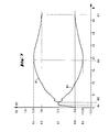
- FIG. 6 shows a diagram from which an example of the variation of the filter coefficients B1 and B2 as a function of the amplitude N of the input signal of the filter can be seen.
- other values of Kl, K2 and Kl3 can also be used.
- the course of B1 with respect to the course of B2 is at least approximately the same as that shown in FIG. 6.
- Each of the coefficient multipliers 32 and 35 is a PROM, for example.
- the delay element 34 is, for example, an image memory used as a digital delay line.
- the filter 2l has the circuit according to FIG. 4 and works with the filter coefficients according to FIG. 6, a non-linear filtering of the input signals is carried out, which has the effect that input signals which have a relatively small amplitude over two successive images are averaged, while input signals that have a relatively large amplitude are not averaged at all and go directly to the output of the filter.
- This has the following effects: - A blurring of the displayed image by averaging echo signals that have relatively large amplitudes is avoided. - The mapping of movements, which are generally represented by relatively large echo signals, is improved compared to previously known systems in which averaging of all echo signals - regardless of their amplitude - is carried out by linear filtering of the echo signals. - By averaging the relatively small echo signals, an improvement in the signal-to-noise ratio of the resulting image is achieved compared to known systems in which no measures are provided to improve this ratio.
- a second embodiment of the filter 2l also has the circuit according to FIG. 4, but works with different filter coefficients.
- An example of the variation of these coefficients as a function of the amplitude of the input signal of the filter can be seen from the diagram shown in FIG. 7.
- K3, K4, K5, K6 and K7 can also be used, provided that K6 is less than 0 and that Kll is equal to or less than 0.
- the course of B1 with respect to the course of B2 is at least approximately the same as that shown in FIG. 7.
- this second embodiment of the filter 2l ie the embodiment with the circuit according to FIG. 4 and the filter coefficients according to FIG. 7, in addition to the effects already mentioned above, the effects with the first embodiment according to FIG 4 and 6 are achieved, a highlighting of the input signals achieved, which correspond to movements in the examined area.
- This second embodiment of the filter 2l therefore also has the function of a fixed character eraser (moving target indicator).
- the input signals of the filter can be averaged over a maximum of 2 images.
- This limit can be exceeded with a recursive filter circuit, such as that shown in Fig. 5, if it works with filter coefficients A, B1 and B2, e.g. vary according to the diagram shown in Fig. 8 as a function of the amplitude N of the input signal of the filter.
- the filter circuit according to FIG. 5 differs from that according to FIG. 4 only in that a feedback path is provided in the circuit according to FIG. 5, in which a coefficient A is introduced by means of a coefficient multiplier 42, and in that the signal and the feedback that results therefrom Input signal of the filter can be added using an adder 4l.
- K7, K8 and Kl2 can also be used, provided that K7 is greater than K8, K8 is greater than Kl2, and that Kl2 is equal to or greater than 0.
- the course of each of the coefficients A, B1 and B2 with respect to the course of the other two coefficients is at least approximately the same as shown in FIG. 8.
- the filter coefficients are determined as follows:
- a function A (N) is chosen. With the values of the coefficient A chosen in this way, the coefficients B1 and B2 are then determined using equations (II) and (III). It is then checked whether the step response of the filter for each value of the amplitude N of the input signal, i.e. is stable for each group of values of the coefficients A, Bl, B2 corresponding to such a value of N, and whether the filter leaves the gray tone distribution of a static image unchanged. If this is not the case, the procedure just described has to be carried out with a new selected function A (N), etc.
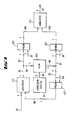
- FIG. 9 shows the block diagram of a circuit with which either a filter 2l according to FIG. 4 with the filter coefficients according to FIG. 6 or FIG. 7, or a filter 2l according to FIG. 5 with the filter coefficients according to FIG. 8 can be produced .
- the input signal is fed to the input of the filter according to FIG. 9 via a 6-bit bus line 3l.
- This bus line is connected to a first input of an adder 4ll.
- the output of the adder 4ll is connected via 7-bit bus lines 9l-93 to a first address input of a PROM 32l and to the data input of a RAM 34l.
- the function of the RAM 34l is controlled by an address counter 94, the output of which is connected to the address input of the RAM 34l via a 17-bit bus line 95.
- the data output of RAM 34l is connected via 7-bit bus lines 96-98 to a first address input of a PROM 35l and to a first address input of a PROM 42l.
- the output of the PROM 42l is connected via a 7-bit bus line 99 connected to a second input of the adder 4ll.
- the outputs of the PROM 32l and 35l are each connected to a first and a second input of an adder 33l via a 7-bit bus line l0l or l02.
- the output signal of the adder 33l is output via a 6-bit bus line 36.
- the PROM 32l, 35l and 42l are used as coefficient multipliers.
- the following coefficients can be optionally introduced:
- each of the PROM 32l, 35l, 42l there are 512 different addresses which are multiplexed via a 9-bit address bus. A word with an 8-bit word length can be read in each address. According to the above description of the block diagram according to FIG. 9, only 7 bits are used.
- Each of the PROM 32l, 35l, 42l has a second address input. A control signal is fed to each of these inputs via a 2-bit bus line 87, 88 and 89, respectively. This control signal is used to select the group of coefficients to be introduced with each PROM.
- the 2-bit control signal can have 4 different values. This means that 4 different groups of filter coefficients per PROM and thus 4 different filters can be selected.
- the RAM 34l has the function of a delay element.
- the storage locations for the image signals are arranged in a matrix with 256 columns and 512 rows. This arrangement corresponds to the arrangement of the scanned points and the arrangement of the displayed pixels.
- Each image signal stored there is encoded in the form of a 7-bit word.
- Control of RAM 34l by address counter 94 causes RAM 34l to function as a shift register. In this way, the image signal for a sampled point of the current scan and the image signal for the same point in the previous scan at the output of the RAM 34l are simultaneously available at the input of the RAM 34l.
Abstract
Verfahren und Vorrichtung zur Erzeugung von Ultraschall-Querschnittbildern eines Körpers, bei welchem Verfahren eine Vielzahl von aufeinanderfolgenden, sich wenigstens teilweise überdeckenden, nach dem Impulsechoverfahren in einer Abtastebene zeilenweise durchgeführten Abtastungen (1,2,3) des Körpers durchgeführt und dadurch Bildsignale in digitaler Form erzeugt werden, die den empfangenen Echos entsprechen, wobei jede Abtastung eine vorbestimmte Anzahl Abtastlinien (4,5,6) und jede von diesen eine vorbestimmte Anzahl Abtastpunkte umfasst, wobei zwischen korrespondierenden Abtastpunkten aufeinanderfolgender Abtastungen ein vorbestimmtes Zeitintervall vorgesehen ist. Zur Verringerung des die Bildqualität limitierenden Rauschens unter Beibehaltung einer guten Darstellung von bewegten Teile im untersuchten Bereich wird für wenigstens einen Teil der Bildpunkte eines angezeigten Querschnittsbildes das Bildsignal, das jeweils einem der angezeigten Bildpunkte entspricht, durch eine Kombination von Bildsignalen erzeugt, die korrespondierenden Abtastpunkten aufeinanderfolgender Abtastungen entsprechen, wobei die Kombination dieser Bildsignale durch eine zeitdiskrete nicht lineare Filterung (21) derselben durchgeführt wird, wobei jeder der Filterkoeffizienten in Funktion der Amplitude des Eingangssignals des Filters variabel ist.Method and device for generating cross-sectional ultrasound images of a body, in which method a plurality of successive, at least partially overlapping, line-by-line scans (1, 2, 3) of the body carried out in a scanning plane after the pulse echo method, and thereby image signals in digital form are generated which correspond to the received echoes, each scan comprising a predetermined number of scan lines (4,5,6) and each of these a predetermined number of scan points, a predetermined time interval being provided between corresponding scan points of successive scans. In order to reduce the noise limiting the image quality while maintaining a good representation of moving parts in the examined area, for at least some of the pixels of a displayed cross-sectional image the image signal, which corresponds to one of the displayed pixels, is generated by a combination of image signals, the corresponding sampling points in succession Samples correspond, the combination of these image signals being carried out by time-discrete non-linear filtering (21) thereof, each of the filter coefficients being variable as a function of the amplitude of the input signal of the filter.
Description
Die Erfindung betrifft ein Verfahren zur Erzeugung von Ultraschall-Querschnittbildern eines Körpers, bei welchem Verfahren eine Vielzahl von aufeinanderfolgenden, sich wenigstens teilweise überdeckenden, nach dem Impulsechoverfahren in einer Abtastebene zeilenweise durchgeführten Abtastungen des Körpers durchgeführt und dadurch Bildsignale in digitaler Form erzeugt werden, die den empfangenen Echos entsprechen, wobei jede Abtastung eine vorbestimmte Anzahl Abtastlinien und jede von diesen eine vorbestimmte Anzahl Abtastpunkte umfasst, wobei zwischen korrespondierenden Abtastpunkten aufeinanderfolgender Abtastungen ein vorbestimmtes Zeitintervall vorgesehen ist.The invention relates to a method for generating ultrasound cross-sectional images of a body, in which method a plurality of successive, at least partially overlapping, line-by-line scans of the body, carried out after the pulse echo method in a scanning plane, and image signals in digital form that generate the received echoes correspond, each scan comprising a predetermined number of scan lines and each of these a predetermined number of scan points, a predetermined time interval being provided between corresponding scan points of successive scans.
Die Erfindung betrifft ausserdem eine Bildsignalaufbereitungsvorrichtung, die zur Durchführung des erfindungsgemässen Verfahrens verwendbar ist, und ein Ultraschall-Abbildungsgerät, das eine solche Vorrichtung enthält.The invention also relates to an image signal processing device that can be used to carry out the method according to the invention and an ultrasound imaging device that contains such a device.
Es ist bekannt (IEEE Transactions on Sonics and Ultrasonics, Vol. SU-3l, No. 4, Juli l984, Seiten l95-2l7), dass bei Verfahren der oben erwähnten Art eine Verringerung des Rauschens, das die Bildqualität vermindert, durch Mittelung der Bildsignale über eine Folge von Bildern erzielt werden kann, dass dabei aber Bewegungen im untersuchten Bereich eine Verwischung des resultierenden Bildes verursachen. Dies ist insbesondere bei der medizinischen Ultraschall-Diagnostik ein erheblicher Nachteil.It is known (IEEE Transactions on Sonics and Ultrasonics, Vol. SU-3l, No. 4, July l984, pages l95-2l7) that in methods of the type mentioned above, a reduction in the noise, which reduces the image quality, can be achieved by averaging the image signals over a sequence of images, but that movements in the area under examination cause the resulting image to be blurred. This is a considerable disadvantage, particularly in medical ultrasound diagnostics.
Der Erfindung liegt daher die Aufgabe zugrunde, den oben erwähnten Nachteil zu beheben.The object of the invention is therefore to remedy the disadvantage mentioned above.
Diese Aufgabe wird mit einem Verfahren der eingangs genannten Art gelöst, das dadurch gekennzeichnet ist, dass für wenigstens einen Teil der Bildpunkte eines angezeigten Querschnittsbildes das Bildsignal, das jeweils einem der angezeigten Bildpunkte entspricht, durch eine Kombination von Bildsignalen erzeugt wird, die korrespondierenden Abtastpunkten aufeinanderfolgender Abtastungen entsprechen, wobei die Kombination dieser Bildsignale durch eine zeitdiskrete nicht lineare Filterung derselben durchgeführt wird, wobei jeder der Filterkoeffizienten in Funktion der Amplitude des Eingangssignals des Filters variabel ist.This object is achieved with a method of the type mentioned at the outset, which is characterized in that for at least some of the pixels of a displayed cross-sectional image, the image signal, which corresponds in each case to one of the displayed pixels, is generated by a combination of image signals, the corresponding sampling points in succession Corresponds to scans, the combination of these image signals being carried out by time-discrete non-linear filtering thereof, each of the filter coefficients being variable as a function of the amplitude of the input signal of the filter.
Gegenstand der Erfindung ist ferner eine Bildsignalaufbereitungsvorrichtung zur Erzeugung eines Ultraschall-Querschnittbildes eines Körpers, die in einem Ultraschall-Abbildungssystem verwendbar ist, mit dem eine Vielzahl von aufeinanderfolgenden, sich wenigstens teilweise überdeckenden, nach den Impulsechoverfahren in einer Abtastebene zeilenweise durchgeführte Abtastungen des Körpers durchführbar sind, um Bildsignale in digitaler Form zu erzeugen, die den empfangenen Echos entsprechen, wobei jede Abtastung eine vorbestimmte Anzahl Abtastlinien und jede von diesen eine vorbestimmte Anzahl Abtastpunkte unfasst, wobei zwischen korrespondierenden Abtastpunkten aufeinanderfolgender Abtastungen ein vorbestimmtes Zeitintervall vorgesehen ist, und welches System eine Ultraschall-Abtastvorrichtung, einen damit verbundenen Sender, einen mit der Ultraschall-Abtastvorrichtung verbundenen Empfänger, einen mit dem Empfänger verbundenen Fernsehmonitor, und eine mit dem Sender, dem Empfänger, und dem Fernsehmonitor verbundene Steuereinheit enthält, wobei der Empfänger eine Detektor-Schaltung zur Erzeugung eines analogen Ausgangssignals enthält, das das jeweils empfangene Echo darstellt. Die erfindungsgemässe Bildsignalaufbereitungsvorrichtung ist dadurch gekennzeichnet, dass
- a) sie der Detektor-Schaltung des Empfängers nachgeschaltet ist, einen der Detektor-Schaltung nachgeschalteten Analog-Digital-Umsetzer, einen diesem Umsetzer nachgeschalteten digitalen Bildspeicher, einen dem Bildspeicher nachgeschalteten Digital-Analog-Umsetzer und ein nicht lineares digitales Filter enthält,
- b) dieses Filter zwischen dem Analog-Digital-Umsetzer und dem Digital-Analog-Umsetzer eingeschaltet ist, und es wenigstens ein Verzögerungsglied enthält, mit dem eine Verzögerung des Eingangssignals der Filters durchführbar ist, deren Dauer gleich dem vorbestimmten Zeitintervall ist, das zwischen korrespondierenden Abtastpunkten aufeinanderfolgender Abtastungen vorgesehen ist, und
- c) jeder der Filterkoeffizienten in Funktion der Amplitude des Eingangssignals des Filters variabel ist.
- a) it is connected downstream of the detector circuit of the receiver, contains an analog-digital converter connected downstream of the detector circuit, a digital image memory connected downstream of this converter, a digital-analog converter connected downstream of the image memory and a non-linear digital filter,
- b) this filter between the analog-digital converter and the digital-analog converter is switched on, and it contains at least one delay element with which a delay of the input signal of the filter can be carried out, the duration of which is equal to the predetermined time interval between corresponding Sampling points of successive scans is provided, and
- c) each of the filter coefficients is variable as a function of the amplitude of the input signal of the filter.
Gegenstand der Erfindung ist ausserdem ein Ultraschall-Abbildungsgerät zur Erzeugung von Ultraschall-Querschnittbildern eines Körpers, mit welchem Gerät eine Vielzahl von aufeinanderfolgenden, sich wenigstens teilweise überdeckenden, nach dem Impulsechoverfahren in einer Abtastebene zeilenweise durchgeführten Abtastungen des Körpers durchführbar sind, um Bildsignale in digitaler Form zu erzeugen, die den empfangenen Echos entsprechen, wobei jede Abtastung eine vorbestimmte Anzahl Abtastlinien und jede von diesen eine vorbestimmte Anzahl Abtastpunkte umfasst, wobei zwischen korrespondierenden Abtastpunkten aufeinanderfolgender Abtastungen ein vorbestimmtes Zeitintervall vorgesehen ist, und welches Gerät eine Ultraschall-Abtastvorrichtung, einen damit verbundenen Sender, einen mit der Ultraschall-Abtastvorrichtung verbundenen Empfänger, einen mit dem Empfänger verbundenen Fernsehmonitor, und eine mit dem Sender, dem Empfänger, und dem Fernsehmonitor verbundene Steuereinheit enthält, wobei der Empfänger eine Detektor-Schaltung zur Erzeugung eines analogen Ausgangssignals enthält. Das erfindungsgemässe Gerät ist dadurch gekennzeichnet, dass es die oben beschriebene Bildsignalaufbereitungsvorrichtung enthält.The invention also relates to an ultrasound imaging device for generating ultrasound cross-sectional images of a body, with which device a multiplicity of successive, at least partially overlapping, line-by-line scans of the body can be carried out according to the pulse echo method in order to image signals in digital form to generate, corresponding to the received echoes, each scan a predetermined number of scan lines and each of these comprises a predetermined number of scanning points, a predetermined time interval being provided between corresponding scanning points of successive scans, and which device comprises an ultrasound scanning device, a transmitter connected thereto, a receiver connected to the ultrasound scanning device, a television monitor connected to the receiver, and one with contains the control unit connected to the transmitter, the receiver, and the television monitor, wherein the receiver contains a detector circuit for generating an analog output signal. The device according to the invention is characterized in that it contains the image signal processing device described above.
Die durch die Erfindung erzielten Vorteile sind im wesentlichen darin zu sehen, dass eine beachtliche Verringerung des Rauschens erzielt wird, ohne dass dabei Bewegungen im untersuchten Bereich eine Verwischung des angezeigten resultierenden Bildes verursachen. Es ist daher nun möglich geworden, gleichzeitig gut erkennbare Ultraschall-Abbildungen von bewegten Organen bzw. Organteilen (z.B. Herzklappen) zu erzeugen und die Qualität solcher Abbildungen durch Verringerung des Rauschens zu verbessern. Die Erfindung hat ferner den Vorteil, dass seine Realisierung einen relativ niedrigen Schaltungsaufwand erfordert.The advantages achieved by the invention are essentially to be seen in the fact that a considerable reduction in noise is achieved without movements in the area under examination causing the resulting resulting image to be blurred. It has now become possible to simultaneously produce easily recognizable ultrasound images of moving organs or parts of organs (e.g. heart valves) and to improve the quality of such images by reducing noise. The invention also has the advantage that its implementation requires a relatively low amount of circuitry.
Weitere Merkmale und Vorteile der Erfindung gehen aus der folgenden, anhand der beiliegenden Zeichnungen vorgenommenen Beschreibung von Ausführungsbeispielen hervor.Further features and advantages of the invention will become apparent from the following description of exemplary embodiments made with reference to the accompanying drawings.
Es zeigen
- Fig. l ein Blockschema eines erfindungsgemässen Ultraschall-Bildgerätes mit einem Sektorscanner.
- Fig. 2 ein Blockschema eines erfindungsgemässen Ultraschall-Bildgerätes mit einem Compoundscanner.
- Fig. 3 ein Blockschema der Bildsignalaufbereitungsvorrichtung 27l in Fig. 2.
- Fig. 4 die Prinzipschaltung einer ersten Ausführungsform des Filters 2l in Figuren l und 3.
- Fig. 5 die Prinzipschaltung einer zweiten Ausführungsform des Filters 2l in Fig. l und 3.
- Fig. 6 ein Diagramm der Filterkoeffizienten für eine erste Ausführung des Filters 2l nach Fig. 4.
- Fig. 7 ein Diagramm der Filterkoeffizienten für eine zweite Ausführung des Filters 2l nach Fig. 4.
- Fig. 8 ein Diagramm der Filterkoeffizienten für eine Ausführung des Filters 2l nach Fig. 5.
- Fig. 9 Ein Blockschema einer Schaltung, mit der wahlweise ein Filter 2l nach Fig. 4 mit den Filterkoeffizienten gemäss Fig. 6 oder gemäss Fig. 7, oder ein Filter 2l nach Fig. 5 mit den Filterkoeffizienten gemäss Fig. 8 hergestellt werden kann.
- 1 shows a block diagram of an ultrasound imaging device according to the invention with a sector scanner.
- 2 shows a block diagram of an ultrasound imaging device according to the invention with a compound scanner.
- FIG. 3 shows a block diagram of the image
signal processing device 271 in FIG. 2. - 4 shows the basic circuit of a first embodiment of the filter 2l in FIGS. 1 and 3.
- 5 shows the basic circuit of a second embodiment of the filter 2l in FIGS. 1 and 3.
- 6 shows a diagram of the filter coefficients for a first embodiment of the filter 2l according to FIG. 4.
- 7 shows a diagram of the filter coefficients for a second embodiment of the filter 2l according to FIG. 4.
- 8 shows a diagram of the filter coefficients for an embodiment of the filter 2l according to FIG. 5.
- FIG. 9 is a block diagram of a circuit with which a filter 2l according to FIG. 4 with the filter coefficients according to FIG. 6 or according to FIG. 7, or a filter 2l according to FIG. 5 with the filter coefficients according to FIG. 8 can be produced.
Fig. l zeigt das Blockdiagramm eines Ultraschall-Bildgeräts zur Durchführung des erfindungsgemässen Verfahrens.1 shows the block diagram of an ultrasound imaging device for carrying out the method according to the invention.
Wie in Fig. l gezeigt steuert ein gepulster Sender l5 über einen Duplexer l4 einen Ultraschallwandler l0 einer Abtastvorrichtung l4l an. Diese Vorrichtung ist ein mechanischer Sektorscanner. Das empfangene Echosignal gelangt über den Duplexer l4 zum Eingang eines Empfängers 26. Der Eingang eines Tiefenausgleich-Verstärkers l6 ist zugleich der Eingang des Empfängers 26. Dem Verstärker l6 ist ein logarithmischer Verstärker l7 nachgeschaltet, der ein Ausgangssignal liefert, das über einen bestimmten Bereich proportional zum Logarithmus des Eingangssignals ist. Der Ausgang des loga rithmischen Verstärkers l7 ist über eine Leitung 29 mit dem Eingang eines Detektors l8 verbunden. Mit diesem Detektor werden z.B. eine Absolutwertbildung und eine Tiefpassfilterung des Ausgangssignals des logarithmischen Verstärkers l7 durchgeführt. Das Ausgangssignal des Detektors l8 wird über eine Leitung 9l abgegeben. Dieses Signal wird in der Bildsignalaufbereitungsvorrichtung 27 mit einem Analog/Digital-Umsetzer l9 analog zu digital gewandelt. Das Ausgangssignal des Umsetzers l9 wird über eine Busleitung 3l dem Eingang eines nicht linearen digitalen Filters 2l zugeführt. Das Ausgangssignal des Filters 2l wird über eine Busleitung 36 abgegeben und in einem Bildspeicher/Normwandler 22 zwischengespeichert. Gleichzeitig wird der Inhalt des Bildspeicher/Normwandlers 22 ausgelesen. Das ausgelesene Signal wird mit einem Digital/Analog-Umsetzer 23 digital zu analog gewandelt. Das Ausgangssignal des Umsetzers 23 ist das Ausgangssignal der Bildsignalaufbereitungsvorrichtung 27. Dieses Ausgangssignal wird als Fernsehnormsignal einem Fernsehmonitor 24 zugeführt.As shown in FIG. 1, a
Der Ultraschallwandler l0 wird von einem Motor l2 bewegt, der durch eine Motorsteuerung l3 angesteuert wird. Die dargestellte Steuerelektronik 25 gibt Befehls- und Synchronisiersignale an alle andere in Fig. l dargestellten Blöcke.The ultrasonic transducer l0 is moved by a motor l2 which is controlled by a motor control l3. The
Das erfindungsgemässe Verfahren ist auch bei Ultraschallabbildungen anwendbar, bei denen die verwendeten Abtastmuster sich nur teilweise überlappen. Das erfindungsgemässe Verfahren kann daher auch mit dem in Fig. 2 durch ein Blockdiagramm dargestellten Ultraschallgerät-Bildgerät durchgeführt werden, das mit einem elektronischen Compoundscanner arbeitet.The method according to the invention can also be used in ultrasound imaging in which the scanning patterns used only partially overlap. The method according to the invention can therefore also be carried out with the ultrasound device / image device shown in FIG. 2 by a block diagram, which works with an electronic compound scanner.
Das Ultraschall-Bildgerät gemäss Fig. 2 enthält eine Wandleranordnung ll4, eine Wandler-Anschlussvorrichtung l6l, einen Sender l5l, einen Empfänger 26l, einen Fernsehmonitor 24 und eine Steuereinheit 25l.The ultrasound imaging device according to FIG. 2 contains a transducer arrangement II4, a transducer connection device 16L, a transmitter 155L, a receiver 26L, a
Die Wandleranordnung ll4 enthält eine längliche Anordnung von aneinander angrenzenden Wandlerelementen. Die Wandleranordnung ll4 kann eine flache Abstrahlfläche 7l haben. In einer bevorzugten Ausführungsform hat aber ihre Abstrahlfläche eine gewisse Krümmung, die eine Fokussierung der Ultraschallwellen in einer zur Abtastebene senkrechten Ebene bewirkt.The transducer arrangement II4 contains an elongated arrangement of adjoining transducer elements. The transducer arrangement II4 can have a
Da das Ultraschall-Bildgerät gemäss Fig. 2 mit einer segmentierten Wandleranordnung ll4 arbeitet, deren Wandlerelemente gruppenweise nacheinander so angesteuert werden, das mehrere Scans mit verschiedenen Richtungswinkeln durchgeführt werden können, enthält die Wandler-Anschlussvorrichtung l6l eine Elemente-Auswahlvorrichtung l60, mit der jedes Wandlerelement der Wandleranordnung ll4 wahlweise mit einem geeigneten Anschluss des Senders l5l verbunden werden kann.Since the ultrasound imaging device according to FIG. 2 works with a segmented transducer arrangement II4, the transducer elements of which are controlled in groups in succession in such a way that several scans can be carried out with different directional angles, the transducer connection device 16l contains an
Die Wandler-Anschlussvorrichtung l6l ist über je eine Busleitung l52 bzw. 262 mit dem Sender l5l bzw. mit dem Empfänger 26l verbunden.The converter connection device l6l is connected via a bus line l52 or 262 to the transmitter l5l or to the receiver 26l.
Der Empfänger 26l hat einen ähnlichen Aufbau wie der Empfänger 26 in Fig. l, enthält aber zusätzlich in Fig. 2 nicht gezeigte Mittel zur Addition der von den einzelnen Wandlerelementen kommenden Echosignale zur Bildung eines resultierenden Echosignals. Der Empfänger 26l enthält u.a. eine Detektor-Schaltung l8 wie diejenige vom Empfänger 26 und eine Bildsignalaufbereitungsvorrichtung 27l, die nachstehend anhand der Fig. 3 im Detail beschrieben ist.The receiver 26l has a structure similar to that of the
Das Ausgangssignal der Detektor-Schaltung l8 wird dem Eingang der Bildsignalverarbeitungsvorrichtung 27l über eine Leitung 9l zugeführt. Die Bildsignale am Ausgang der Vorrichtung 27l werden dem Fernsehmonitor 24 über eine Leitung 36l zugeführt.The output signal of the
Die Steuereinheit 25l enthält die notwendigen Mittel zur Steuerung der Funktion aller anderen in Fig. 2 gezeigten Blöke.The control unit 25l contains the necessary means for controlling the function of all other blocks shown in FIG. 2.
Im unteren Teil der Fig. 2 ist die Verwendung des dort gezeigten Bildgerätes bei der Untersuchung eines Körperteils ll eines Patienten schematisch dargestellt. Wie in dieser Figur gezeigt, wird die Wandleranordnung ll4 auf die Haut lll des zu untersuchenden Körperteils ll aufgesetzt, wobei ein Uebertragungsgel ll3 zwischen die Abstrahlfläche der Wandlereinrichtung und die Haut des Patienten gebracht wird.In the lower part of FIG. 2, the use of the image device shown there for examining a
Das in Fig. 2 gezeigte Abbildungssystem wird so betrieben, dass mit der Wandleranordnung ll4 wenigstens zwei verschiedene, sich teilweise überdeckende Abtastungen in der Abtastebene nach dem Impulsechoverfahren durchgeführt werden, um ein zusammengesetztes Querschnittbild, z.B. von einem internen Organ l2l, zu erzeugen. Dabei werden z.B. drei solcher Abtastungen l, 2, 3 in rascher Folge nacheinander durchgeführt. Bei jeder dieser Abtastungen werden in rascher Folge Gruppen von Wandlerelementen der Wandleranordnung ll4 verwendet, die Ultraschallimpulse in eine bestimmte Richtung senden und die entsprechenden Echos empfangen. Auf diese Weise wird der untersuchte Körperteil bei jeder der Abtastungen l, 2 bzw. 3 mit einer raschen Folge von zueinander parallelen Ultraschallstrahlen bestrahlt. In der Fig. 2 sind für jede der Abtastungen l, 2, 3 die entsprechenden Strahlen (hier auch Abtastlinien genannt) 4, 5 bzw. 6 mit verschiedenen Linien dargestellt. Durch das soeben beschrieben Verfahren wird der untersuchte Körperteil mit dem in Fig. l gezeigten, zusammengesetzten Abtastmuster in sehr kurzer Zeit bestrahlt.The imaging system shown in Fig. 2 is operated in such a way that with the transducer arrangement II4 at least two different, partially overlapping scans are carried out in the scanning plane according to the pulse echo method in order to produce a composite cross-sectional image, e.g. by an internal organ l2l. Here, e.g. three
Im Sender l5l werden die Sendesignale für die Wandlerelemente der Wandleranordnung ll4 erzeugt, und die von den Wandlerelementen gelieferten Echosignale werden dem Empfänger 26l über die Leitung 262 zugeführt. Die empfangenen Echosignale werden am Ausgang des Detektors l8 und über die Leitung 9l abgegeben.The transmit signals for the transducer elements of transducer arrangement ll4 are generated in transmitter 15l, and those of Echo signals supplied to transducer elements are fed to the
Durch die verschiedenen, in Fig. 2 gezeigten Abtastungen l, 2 bzw. 3 werden Einzelbilder aufgenommen. Die nachstehend im Detail beschriebene Bildsignalaufbereitungsvorrichtung 27l dient u.a. dazu, ein elektronisches Compounding, d.h. eine Zusammensetzung dieser Einzelbilder durchzuführen, um ein zusammengesetztes Bild zu erzeugen, das Compound-Bild genannt wird.Individual images are recorded by the
Wie in Fig. 3 durch ein Blockschema dargestellt, enthält die Bildsignalaufbereitungsvorrichtung 27l in Fig. 2 die gleichen Blöcke l9, 2l, 22 und 23 wie die Vorrichtung 27 in Fig. l und zusätzlich eine zwischen dem Bildspeicher/Normwandler 22 und dem Digital/Analog-Umsetzer 23 eingeschaltete Auswerteeinheit 22l. Diese Einheit dient dazu, die aus dem Bildspeicher/Normwandler 22 gelesenen Bildsignale zur Erzeugung des Compound-Bildes miteinander zu kombinieren, z.B. durch Mittelwertbildung der Bildsignale.As represented by a block diagram in FIG. 3, the image signal processing device 27l in FIG. 2 contains the same blocks l9, 2l, 22 and 23 as the
Das Ausgangssignal der Bildsignalaufbereitungsvorrichtung 27l wird über die Leitung 36l dem Fernsehmonitor zugeführt. Mit dem Fernsehmonitor 24 wird dann ein Compound-Bild angezeigt, d.h. ein Bild, das durch die oben erwähnte, elektronische Zusammensetzung von Einzelbildern erzeugt wird.The output signal of the image signal processing device 27l is fed via line 36l to the television monitor. A compound image is then displayed on the
Die vorliegende Erfindung betrifft insbesondere die Ausbildung der Bildsignalaufbereitungsvorrichtung 27 in Fig. l und 27l in Fig. 2. Diese Vorrichtung ist insbesondere dadurch gekennzeichnet, dass sie ein nicht lineares digitales Filter 2l enthält, das zwischen dem Analog/Digital-Umsetzer l9 und dem Digital/Analog-Umsetzer 23 eingeschaltet ist, und dass die Koeffizienten des Filters 2l in Funktion der Amplitude seines Eingangssignals des Filters variabel sind. In den in Figuren l und 2 gezeigten Schaltungen ist der Filter 2l zwischen dem Analog/Digital-Umsetzer l9 und dem Bildspeicher/Normwandler 22 eingeschaltet. Der Filter 2l kann aber auch dem Block 22 in Fig. l oder Fig. 2, oder dem Block 22l in Fig. 3 nachgeschaltet sein, wenn dies bei der Bestimmung der Filterkoeffizienten berücksichtigt wird.The present invention relates in particular to the design of the image
Die Prinzipschaltung einer ersten Ausführungsform des Filters 2l ist in der Fig. 4 dargestellt. Dieser Filter ist ein Transversalfilter erster Ordnung, und enthält ein Verzögerungsglied 34, Koeffizientmultiplizierer 32 und 35 und einen Addierer 33. Ueber die Busleitung 3l werden dem Eingang des Filters 2l die vom Ausgang des Analog/Digital/Umsetzers l9 gelieferten Signale zugeführt. Das Ausgangssignal des Filters 2l wird über die Leitung 36 abgegeben.The basic circuit of a first embodiment of the filter 2l is shown in FIG. 4. This filter is a transversal filter of the first order and contains a
Mit dem Koeffizientenmultiplizierer 32 wird ein Koeffizient Bl und mit dem Koeffizientenmultiplizierer 35 ein Koeffizient B2 eingeführt.A coefficient B1 is introduced with the
Mit dem Verzögerungsglied 34 wird eine Verzögerung des Eingangssignals des Filters 2l durchgeführt, deren Dauer gleich dem vorbestimmten Zeitintervall ist, das zwischen korrespondierenden Abtastpunkten aufeinanderfolgender Abtastungen vorgesehen ist.The
Die Koeffizientenmultiplizierer 32 und 35 sind so eingerichtet, das jeder der Filterkoeffizienten Bl bzw. B2 in Funktion der Amplitude des Eingangssignals des Filters variabel ist. Die Fig. 6 zeigt ein Diagramm, aus dem ein Beispiel der Variation der Filterkoeffizienten Bl und B2 in Funktion der Amplitude N des Eingangssignals des Filters, ersichtlich ist.The coefficient multipliers 32 and 35 are set up so that each of the filter coefficients B1 and B2 is variable as a function of the amplitude of the input signal of the filter. FIG. 6 shows a diagram from which an example of the variation of the filter coefficients B1 and B2 as a function of the amplitude N of the input signal of the filter can be seen.
Die Werte der Amplitude N des Eingangssignals des Filters liegen zwischen dem Wert N=0, der einem schwarzen Punkt der Fernsehanzeige entspricht, und dem Wert N=63, der einem weissen Punkt der Fernsehanzeige entspricht.The values of the amplitude N of the input signal of the filter lie between the value N = 0, which corresponds to a black dot on the television display, and the value N = 63, which corresponds to one white dot corresponds to the television display.
Gemäss Fig. 6 sind die Filterkoeffizienten Bl und B2 durch folgende Funktionen der Amplitude N des Eingangssignals des Filters definiert:
- für relativ niedrige Werte von N in einem Bereich von einem Wert Nl bis zu einem Wert N2 gilt:
Bl=B2=Kl;
- für mittlere Werte von N in einem Bereich zwischen dem Wert N2 und einem Wert N3:
nimmt Bl vom Wert Bl=Kl ausgehend mit zunehmender N zu und erreicht den Wert Bl=K2 bei N=N3,
nimmt B2 vom Wert B2=Kl ausgehend mit zunehmender N ab und erreicht den Wert B2=Kl3 bei N=N3;
- für relativ hohe Werte von N, die gleich oder grösser als N3 sind, gilt: Bl=K2 und B2=Kl3,
wobei Nl, N2, N3 vorbestimmte Werte der Amplitude des Eingangssignals N und Kl, K2, Kl3 feste Werte sind.6, the filter coefficients B1 and B2 are defined by the following functions of the amplitude N of the input signal of the filter:
- for relatively low values of N in a range from a value Nl to a value N2:
Bl = B2 = Kl;
- for medium values of N in a range between the value N2 and a value N3:
Bl increases from the value Bl = Kl with increasing N and reaches the value Bl = K2 at N = N3,
B2 decreases from the value B2 = Kl starting with increasing N and reaches the value B2 = Kl3 with N = N3;
- for relatively high values of N, which are equal to or greater than N3, the following applies: B1 = K2 and B2 = Kl3,
where Nl, N2, N3 are predetermined values of the amplitude of the input signal N and Kl, K2, Kl3 are fixed values.
Im Beispiel gemäss Fig. 6 ist Kl=0,5, K2=l,00 und Kl3=0. Im allgemeinen können auch andere Werte von Kl, K2 und Kl3 verwendet werden. In bevorzugten Ausführungsformen ist aber der Verlauf von Bl in bezug auf den Verlauf von B2 wenigstens annähernd derselbe wie in Fig. 6 dargestellt.In the example according to FIG. 6, Kl = 0.5, K2 = 1.00, and Kl3 = 0. In general, other values of Kl, K2 and Kl3 can also be used. In preferred embodiments, however, the course of B1 with respect to the course of B2 is at least approximately the same as that shown in FIG. 6.
Jeder der Koeffizientenmultiplizierer 32 und 35 ist z.B. ein PROM. Das Verzögerungsglied 34 ist z.B. ein als digitale Verzögerungsleitung verwendeter Bildspeicher.Each of the
Wenn de Filter 2l die Schaltung gemäss Fig. 4 hat und mit den Filterkoeffizienten gemäss Fig. 6 arbeitet, wird damit eine nicht lineare Filterung der Eingangssignale durchgeführt, welche die Wirkung hat, dass Eingangssignale, die eine relativ kleine Amplitude haben, über zwei aufeinanderfolgenden Bilder gemittelt werden, während Eingangssignale, die eine relativ gross Amplitude haben, überhaupt nicht gemittelt werden und direkt zum Ausgang des Filters gelangen. Dadurch werden folgende Effekte erzielt:
- Eine Verwischung des angezeigten Bildes durch Mittelung von Echosignalen, die relativ grosse Amplituden haben, wird vermieden.
- Die Abbildung von Bewegungen, die im allgemeinen durch relativ grosse Echosignale vertreten sind, wird gegenüber bisher bekannten Systemen verbessert, bei denen durch eine lineare Filterung der Echosignale eine Mittelung aller Echosignale - unabhängig von ihrer Amplitude - durchgeführt wird.
- Durch die Mittelung der relativ kleinen Echosignale wird eine Verbesserung des Signal-Rauschen-Verhältnisses des resultierenden Bildes gegenüber bekannten Systemen erzielt, bei denen keine Massnahmen zur Verbesserung dieses Verhältnisses vorgesehen sind.If the filter 2l has the circuit according to FIG. 4 and works with the filter coefficients according to FIG. 6, a non-linear filtering of the input signals is carried out, which has the effect that input signals which have a relatively small amplitude over two successive images are averaged, while input signals that have a relatively large amplitude are not averaged at all and go directly to the output of the filter. This has the following effects:
- A blurring of the displayed image by averaging echo signals that have relatively large amplitudes is avoided.
- The mapping of movements, which are generally represented by relatively large echo signals, is improved compared to previously known systems in which averaging of all echo signals - regardless of their amplitude - is carried out by linear filtering of the echo signals.
- By averaging the relatively small echo signals, an improvement in the signal-to-noise ratio of the resulting image is achieved compared to known systems in which no measures are provided to improve this ratio.
Eine zweite Ausführungsform des Filters 2l hat ebenfalls die Schaltung gemäss Fig. 4, aber arbeitet mit anderen Filterkoeffizienten. Ein Beispiel der Variation dieser Koeffizienten in Funktion der Amplitude des Eingangssignals des Filters ist aus dem in Fig. 7 dargestellten Diagramm ersichtlich. Auch in diesem Diagramm liegen die Werte von B zwischen den oben definierten Extremwerten N=0 und N=63.A second embodiment of the filter 2l also has the circuit according to FIG. 4, but works with different filter coefficients. An example of the variation of these coefficients as a function of the amplitude of the input signal of the filter can be seen from the diagram shown in FIG. 7. In this diagram too, the values of B lie between the extreme values N = 0 and N = 63 defined above.
Gemäss Fig. 7 sind die Filterkoeffizienten Bl und B2 durch folgende Funktionen der Amplitude des Eingangssignals des Filters definiert:
- für relativ sehr niedrige Werte von N in einem Bereich von einem Wert N4 bis zu einem Wert N5 gilt: Bl=B2=K3;
- für relativ niedrige und mittlere Werte von N in einem Bereich zwischen dem Wert N5 und einem Wert N7:
nimmt Bl vom Wert Bl=K3 ausgehend mit zunehmender N zu, bis er bei N=N6 einen maximal Wert Bl=K4 erreicht, nimmt von dort mit zunehmender N ab, und erreicht den Wert Bl=K5 bei N=N7;
nimmt B2 vom Wert B2=K3 ausgehend mit zunehmender N ab, bis er bei N=N6 einen minimal Wert B2=K6 erreicht, der kleiner als 0 ist, nimmt von dort mit zunehmender N zu, und erreicht den Wert B2=Kll bei N=N7, wobei Kll gleich oder kleiner als 0 ist;
- für relativ hohe Werte von N, die gleich oder grösser als N7 sind, gilt: Bl=K5 und B2=Kll,
wobei N4, N5, N6, N7 vorbestimmte Werte der Amplitude des Eingangssignals N und K3, K4, K5, K6, Kll feste Werte sind.7, the filter coefficients B1 and B2 are defined by the following functions of the amplitude of the input signal of the filter:
- for relatively very low values of N in a range from a value N4 to a value N5: Bl = B2 = K3;
- for relatively low and medium values of N in a range between the value N5 and a value N7:
Starting from the value Bl = K3, Bl increases with increasing N until it reaches a maximum value Bl = K4 at N = N6, decreases from there with increasing N, and reaches the value Bl = K5 with N = N7;
B2 decreases from the value B2 = K3 with increasing N until it reaches a minimum value B2 = K6 which is less than 0 at N = N6, increases from there with increasing N, and reaches the value B2 = Kll at N = N7, where Kll is equal to or less than 0;
- for relatively high values of N, which are equal to or greater than N7, the following applies: Bl = K5 and B2 = Kll,
where N4, N5, N6, N7 are predetermined values of the amplitude of the input signal N and K3, K4, K5, K6, Kll are fixed values.
Im Beispiel gemäss Fig. 7 ist K3=0,5, K4=l,25, K5=l,00, K6=-0,25 und Kll=0. Im allgemeinen können auch andere Werte von K3, K4, K5, K6 und K7 verwendet werden, vorausgesetzt, dass K6 kleiner als 0 ist und dass Kll gleich oder kleiner als 0 ist. In bevorzugten Ausführungsformen ist aber der Verlauf von Bl in bezug auf den Verlauf von B2 wenigstens annähernd derselbe wie in Fig. 7 dargestellt.In the example according to FIG. 7, K3 = 0.5, K4 = 1.25, K5 = 1.00, K6 = -0.25 and Kll = 0. In general, other values of K3, K4, K5, K6 and K7 can also be used, provided that K6 is less than 0 and that Kll is equal to or less than 0. In preferred embodiments, however, the course of B1 with respect to the course of B2 is at least approximately the same as that shown in FIG. 7.
Mit dieser zweiten Ausführungsform des Filters 2l, d.h. die Ausführung mit der Schaltung gemäss Fig. 4 und die Filterkoeffizienten gemäss Fig. 7, wird ausser der bereits oben erwähnten Effekte, die mit der ersten Ausführungsform gemäss Fig. 4 und 6 erzielt werden, eine Hervorhebung der Eingangssignale erzielt, die Bewegungen im untersuchten Bereich entsprechen. Diese zweite Ausführungsform des Filters 2l hat also zusätzlich die Funktion eines Festzeichenlöschers (Moving Target Indicator).With this second embodiment of the filter 2l, ie the embodiment with the circuit according to FIG. 4 and the filter coefficients according to FIG. 7, in addition to the effects already mentioned above, the effects with the first embodiment according to FIG 4 and 6 are achieved, a highlighting of the input signals achieved, which correspond to movements in the examined area. This second embodiment of the filter 2l therefore also has the function of a fixed character eraser (moving target indicator).
Mit den oben beschrieben Ausführungsformen des Filters 2l können die Eingangssignale des Filters höchstens über 2 Bilder gemittelt werden. Diese Grenze kann mit einer rekursiven Filterschaltung überschritten werden, wie diejenige die in Fig. 5 dargestellt ist, wenn diese mit Filterkoeffizienten A, Bl und B2 arbeitet, die z.B. nach dem in Fig. 8 dargestellten Diagramm in Funktion der Amplitude N des Eingangssignals des Filters variieren.With the embodiments of the filter 2l described above, the input signals of the filter can be averaged over a maximum of 2 images. This limit can be exceeded with a recursive filter circuit, such as that shown in Fig. 5, if it works with filter coefficients A, B1 and B2, e.g. vary according to the diagram shown in Fig. 8 as a function of the amplitude N of the input signal of the filter.
Die Filterschaltung nach Fig. 5 hat eine kanonische Struktur erster Ordnung.5 has a first order canonical structure.
Die Filterschaltung gemäss Fig. 5 unterscheidet sich von derjenigen gemäss Fig. 4 lediglich darin, dass in der Schaltung gemäss Fig. 5 ein Rückkopplungspfad vorgesehen ist, in dem ein Koeffizient A mittels eines Koeffizientenmultiplizierers 42 eingeführt wird, und dass das dadurch rückgekoppelte Signal und das Eingangssignal des Filters mittels eines Addierers 4l addiert werden.The filter circuit according to FIG. 5 differs from that according to FIG. 4 only in that a feedback path is provided in the circuit according to FIG. 5, in which a coefficient A is introduced by means of a
Gemäss Fig. 8 sind die Filterkoeffizienten A, Bl, B2 durch folgende Funktionen der Amplitude N des Eingangssignals des Filters definiert:
- für relativ sehr niedrige Werte von N in einem Bereich von einem Wert N8 bis zu einem Wert Nl0 gilt A=K7;
- für relativ niedrige und mittlere Werte von N in einem Bereich zwischen dem Wert Nl0 und einem Wert Nll:
variiert A schwankend, nimmt aber vom Wert A=K7 ausgehend mit zunehmender N allmählich ab, bis er den Wert A=Kl2 bei N=Nll erreicht, wobei Kl2 gleich oder grösser als 0 ist;
- für relativ sehr niedrige Werte von N in einem Bereich zwischen dem Wert N8 und einem Wert N9, und für zunehmende Werte von N nimmt Bl vom Wert Bl=K7 ausgehend ab, und nimmt B2 vom Wert B2=0 ausgehend zu, bis Bl und B2 bei N=N9 einen und denselben Wert Bl=B2=K8 erreichen;
- für Werte von N, die gleich oder grösser als N9 sind, gilt Bl=B2, wobei Koeffizienten schwankend variieren, aber mit zunehmender N allmählich zunehmen,
wobei N8, N9, Nl0, Nll vorbestimmte Werte der Amplitude des Eingangssignals N und K7, K8, Kl2 feste Werte sind.8, the filter coefficients A, B1, B2 are defined by the following functions of the amplitude N of the input signal of the filter:
- for relatively very low values of N in a range from a value N8 to a value N10, A = K7 applies;
- for relatively low and medium values of N in a range between the value Nl0 and a value Nll:
A varies with fluctuation, but gradually decreases from N = K7 with increasing N until it reaches A = Kl2 at N = Nll, whereby Kl2 is equal to or greater than Is 0;
for relatively very low values of N in a range between the value N8 and a value N9, and for increasing values of N, Bl decreases from the value Bl = K7 and B2 increases from the value B2 = 0 until Bl and B2 at N = N9 achieve the same value Bl = B2 = K8;
- for values of N which are equal to or greater than N9, Bl = B2 applies, where coefficients vary with fluctuation, but gradually increase with increasing N,
where N8, N9, Nl0, Nll are predetermined values of the amplitude of the input signal N and K7, K8, Kl2 are fixed values.
Auch im Diagramm gemäss Fig. 8 liegen die Werte von N zwischen den oben definierten Extremwerten N=0 und N=63.In the diagram according to FIG. 8 too, the values of N lie between the extreme values N = 0 and N = 63 defined above.
Im Beispiel gemäss Fig. 8 ist K7=0,5, K8=0,l7, und Kl2=0. Im allgemeinen können auch andere Werte von K7, K8 und Kl2 verwendet werden, vorausgesetzt, dass K7 grösser als K8, K8 grösser als Kl2, und dass Kl2 gleich oder grösser als 0 ist. In bevorzugten Ausführungsformen ist aber der Verlauf jedes der Koeffizienten A, Bl und B2 in bezug auf den Verlauf der anderen zwei Koeffizienten wenigstens annähernd derselbe wie in Fig. 8 dargestellt.In the example according to FIG. 8, K7 = 0.5, K8 = 0, l7, and Kl2 = 0. In general, other values of K7, K8 and Kl2 can also be used, provided that K7 is greater than K8, K8 is greater than Kl2, and that Kl2 is equal to or greater than 0. In preferred embodiments, however, the course of each of the coefficients A, B1 and B2 with respect to the course of the other two coefficients is at least approximately the same as shown in FIG. 8.
Bei der Bestimmung der Werte der Filterkoeffizienten A, Bl, B2 des Filters nach Fig. 5 sind zwei Aspekte zu berücksichtigen:
- Es ist in der Regel erwünscht, dass die Filterung die Grautonverteilung eines statischen Bildes nicht ändert, d.h. dass die Filterung keine Kompression der Bildsignale verursacht. Um diese Bedingung zu erfüllen, muss die Uebertragungsfunktion des Filters H (z) für z=l gleich l sein, d.h. H (z) = l für z=l. Für einen rekursiven Filter, der eine kanonische Struktur erster Ordnung hat, muss also die Bedingung erfüllt werden:
H (z) = (Bl + B2.z⁻¹)/(l-A.z⁻¹) = l für z = l (I)
Daraus ergibt sich die Bedingung:
(Bl + B2)/(l-A) = l (II)When determining the values of the filter coefficients A, Bl, B2 of the filter according to FIG. 5, two aspects have to be taken into account:
- It is usually desirable that the filtering does not change the gray tone distribution of a static image, ie that the filtering does not cause compression of the image signals. In order to meet this condition, the transfer function of the filter H (z) for z = l must be l, ie H (z) = l for z = l. For a recursive filter that has a first-order canonical structure, the condition must therefore be met:
H (z) = (Bl + B2.z⁻¹) / (lA.z⁻¹) = l for z = l (I)
This results in the condition:
(Bl + B2) / (lA) = l (II)
Diese Bedingung (II) gilt auch für die oben beschriebenen Ausführungsbeispiele mit der Filterschaltung gemäss Fig. 4.This condition (II) also applies to the exemplary embodiments described above with the filter circuit according to FIG. 4.
Wenn eine Kompression der Echosignale durchgeführt wird, muss die l auf der rechten Seite der Gleichung (II) durch eine Funktion der Amplitude N die der Kompression entspricht ersetzt werden.When compressing the echo signals, the l on the right side of equation (II) must be replaced by a function of the amplitude N that corresponds to the compression.
- Die Filterkoeffizienten müssen ausserdem so gewählt werden, dass das Filter stabil ist. Da die Funktion A(N).N nicht monoton ist, treten Schwingungen am Eingang (und am Ausgang) des Verzögerungsgliedes 34 für gewisse Werte des Eingangssignals des Filters auf. Durch Computersimulation ist es möglich, die Funktion A(N).N so zu bestimmen, dass die Frequenz solcher Schwingungen die Hälfte der Bildfrequenz ist. Auf diese Weise hat man lediglich zwei mögliche Zustände für jeden Wert des Eingangssignals, der solche Schwingungen verursacht. Es genügt daher bei der Bestimmung der Koeffizienten Bl und B2 die Bedingung
Bl (N) = B2 (N) (III)
zu erfüllen, damit solche Schwingungen sich durch Addition gegenseitig aufheben und amAusgang des Filters nicht erscheinen.- The filter coefficients must also be selected so that the filter is stable. Since the function A (N) .N is not monotonic, vibrations occur at the input (and at the output) of the
Bl (N) = B2 (N) (III)
to ensure that such vibrations cancel each other out by addition and do not appear at the output of the filter.
Unter Berücksichtigung der oben erwähnten Bedingungen (i)-(III) geht man bei der Bestimmung der Filterkoeffizienten wie folgt vor:Taking into account the conditions (i) - (III) mentioned above, the filter coefficients are determined as follows:
Zuerst wird eine Funktion A(N) gewählt. Mit den so gewählten Werten des Koeffizienten A werden dann die Koeffizienten Bl und B2 anhand der Gleichungen (II) und (III) bestimmt. Daraufhin wird geprüft, ob die Sprungantwort des Filters für jeden Wert der Amplitude N des Eingangssignals, d.h. für jede Gruppe von Werten der Koeffizienten A, Bl, B2, die einem solchen Wert von N entspricht, stabil ist, und ob der Filter die Grautonverteilung eines statischen Bildes unverändert lässt. Wenn dies nicht der Fall ist, muss man das soeben beschriebene Verfahren mit einer neuen gewählten Funktion A(N) durchführen, usw.First a function A (N) is chosen. With the values of the coefficient A chosen in this way, the coefficients B1 and B2 are then determined using equations (II) and (III). It is then checked whether the step response of the filter for each value of the amplitude N of the input signal, i.e. is stable for each group of values of the coefficients A, Bl, B2 corresponding to such a value of N, and whether the filter leaves the gray tone distribution of a static image unchanged. If this is not the case, the procedure just described has to be carried out with a new selected function A (N), etc.
Mit dieser dritten Ausführungsform gemäss Fig. 5 und 8 werden folgende Vorteile gegenüber der oben beschriebenen ersten und zweiten Ausführungsform erzielt: Es wird ein noch höheres Signal-Rauschen-Verhältnis bei gutter, klar erkennbarer Darstellung von Bewegungen im untersuchten Bereich.The following advantages over the first and second embodiments described above are achieved with this third embodiment according to FIGS. 5 and 8: An even higher signal-to-noise ratio is achieved with a good, clearly recognizable representation of movements in the examined area.
Die Fig. 9 zeigt das Blockschema einer Schaltung, mit der wahlweise ein Filter 2l nach Fig. 4 mit den Filterkoeffizienten gemäss Fig. 6 oder Fig. 7, oder ein Filter 2l nach Fig. 5 mit den Filterkoeffizienten gemäss Fig. 8 hergestellt werden kann.FIG. 9 shows the block diagram of a circuit with which either a filter 2l according to FIG. 4 with the filter coefficients according to FIG. 6 or FIG. 7, or a filter 2l according to FIG. 5 with the filter coefficients according to FIG. 8 can be produced .
Das Eingangssignal wird dem Eingang des Filters nach Fig. 9 über ein 6-Bit Busleitung 3l zugeführt. Diese Busleitung ist mit einem ersten Eingang eines Addierers 4ll verbunden. Der Ausgang des Addierers 4ll ist über 7-Bit Busleitungen 9l-93 mit einem ersten Adressen-Eingang eines PROM 32l und mit dem Data-Eingang eines RAM 34l verbunden. Die Funktion des RAM 34l wird von einem Adressenzähler 94 gesteuert, dessen Ausgang über eine l7-Bit Busleitung 95 mit dem Adressen-Eingang des RAM 34l verbunden ist. Der Data-Ausgang des RAM 34l ist über 7-Bit Busleitungen 96-98 mit einem ersten Adressen-Eingang eines PROM 35l und mit einem ersten Adressen-Eingang eines PROM 42l verbunden. Der Ausgang des PROM 42l ist über eine 7-Bit Busleitung 99 mit einem zweiten Eingang des Addierers 4ll verbunden. Die Ausgänge der PROM 32l bzw. 35l sind über je eine 7-Bit busleitung l0l bzw. l02 mit einem ersten bzw. einem zweiten Eingang eines Addierers 33l verbunden. Das Ausgangssignal des Addierers 33l wird über eine 6-Bit Busleitung 36 abgegeben.The input signal is fed to the input of the filter according to FIG. 9 via a 6-bit bus line 3l. This bus line is connected to a first input of an adder 4ll. The output of the adder 4ll is connected via 7-bit bus lines 9l-93 to a first address input of a PROM 32l and to the data input of a RAM 34l. The function of the RAM 34l is controlled by an
Die PROM 32l, 35l und 42l werden als Koeffizientenmultiplizierer verwendet. Damit können wahlweise z.B. folgende Koeffizienten eingeführt werden:

In jedem der PROM 32l, 35l, 42l gibt es 5l2 verschiedene Adressen, die über einen 9-Bit Adressenbus multiplexiert sind. In jeder Adresse kann ein Wort mit einer Wortlänge von 8-Bit gelesen werden. Gemäss der obigen Beschreibung des Blockschemas gemäss Fig. 9 werden davon nur 7 Bit verwendet. Jeder der PROM 32l, 35l, 42l hat einen zweiten Adressen-Eingang. Ein Steuersignal wird jedem dieser Eingänge über je eine 2-Bit Busleitung 87, 88 bzw. 89 zugeführt. Mit diesem Steuersignal wird die Gruppe von Koeffizienten gewählt, die mit Jedem PROM eingeführt werden soll. Das 2-Bit Steuersignal kann 4 verschiedene Werte haben. Damit könnet also 4 veschiedene Gruppen von Filterkoeffizienten pro PROM und dadurch 4 verschiedene Filter gewählt werden.In each of the PROM 32l, 35l, 42l there are 512 different addresses which are multiplexed via a 9-bit address bus. A word with an 8-bit word length can be read in each address. According to the above description of the block diagram according to FIG. 9, only 7 bits are used. Each of the PROM 32l, 35l, 42l has a second address input. A control signal is fed to each of these inputs via a 2-
In der Schaltung nach Fig. 9 hat der RAM 34l die Funktion eines Verzögerungsgliedes. Im RAM 34l sind die Speicherplätze für die Bildsignale in einer Matrix mit 256 Spalten und 5l2 Zeilen angeordnet. Diese Anordnung entspricht der Anordnung der abgetasteten Punkte und der Anordnung der angezeigten Bildpunkte. Jedes dort gespeicherte Bildsignal ist in Form eines 7-Bit Wortes kodiert.In the circuit according to FIG. 9, the RAM 34l has the function of a delay element. In the RAM 34l, the storage locations for the image signals are arranged in a matrix with 256 columns and 512 rows. This arrangement corresponds to the arrangement of the scanned points and the arrangement of the displayed pixels. Each image signal stored there is encoded in the form of a 7-bit word.
Die Steuerung des RAM 34l durch den Adresszähler 94 bewirkt, dass der RAM 34l als ein Schieberegister funktioniert. Auf diese Weise hat man gleichzeitig am Eingang des RAM 34l das Bildsignal für einen abgetasteten Punkt der laufenden Abtastung und am Ausgang des RAM 34l das Bildsignal für den gleichen Punkt bei der vorhergehenden Abtastung.Control of RAM 34l by
Claims (10)
dadurch gekennzeichnet, dass
für wenigstens einen Teil der Bildpunkte eines angezeigten Querschnittsbildes das Bildsignal, das jeweils einem der angezeigten Bildpunkte entspricht, durch eine Kombination von Bildsignalen erzeugt wird, die korrespondierenden Abtastpunkten aufeinanderfolgender Abtastungen entsprechen, wobei die Kombination dieser Bildsignale durch eine zeitdiskrete nicht lineare Filterung derselben durchgeführt wird, wobei jeder der Filterkoeffizienten in Funktion der Amplitude des Eingangssignals des Filters variabel ist.1. A method for generating cross-sectional ultrasound images of a body, in which method a plurality of successive, at least partially overlapping, line-by-line scans of the body are carried out after the pulse echo method in a scanning plane, and image signals are thereby generated in digital form that correspond to the received echoes correspond, wherein each scan comprises a predetermined number of scan lines and each of these comprises a predetermined number of scan points, a predetermined time interval being provided between corresponding scan points of successive scans,
characterized in that
for at least some of the pixels of a displayed cross-sectional image, the image signal, which corresponds in each case to one of the displayed pixels, is generated by a combination of image signals which correspond to corresponding sampling points of successive scans, the combination of these image signals being carried out by time-discrete non-linear filtering thereof, each of the filter coefficients being variable as a function of the amplitude of the input signal to the filter.
welches System eine Ultraschall-Abtastvorrichtung (l4l, ll4), einen damit verbundenen Sender (l5, l5l), einen mit der Ultraschall-Abtastvorrichtung verbundenen Fernsehmonitor (24), und eine mit dem Sender, dem Empfänger, und dem Fernsehmonitor verbundene Steuereinheit (25, 25l) enthält,
wobei der Empfänger eine Detektor-Schaltung (l8) zur Erzeugung eines analogen Ausgangssignals enthält, das das jeweils empfangene Echo darstellt, dadurch gekennzeichnet, dass
which system comprises an ultrasound scanner (l4l, ll4), an associated transmitter (l5, l5l), a television monitor (24) connected to the ultrasound scanner, and a control unit (25.) connected to the transmitter, the receiver, and the television monitor , 25l) contains
wherein the receiver contains a detector circuit (18) for generating an analog output signal which represents the respective received echo, characterized in that
- für relativ niedrige Werte von N in einem Bereich von einem Wert Nl bis zu einem Wert N2 gilt: Bl = B2 = Kl;
- für mittlere Werte von N in einem Bereich zwischen dem Wert N2 und einem Wert N3:
nimmt Bl vom Wert Bl=Kl ausgehend mit zunehmender N zu und erreicht den Wert Bl=K2 bei N=N3,
nimmt B2 vom Wert B2=Kl ausgehend mit zunehmender N ab und errieicht den Wert B2=Kl3 bei N=N3;
- für relativ hohe Werte von N die gleich oder grösser als N3 sind, gilt: Bl=K₂ und B2=Kl3,
wobei Nl, N2, N3 vorbestimmte Werte der Amplitude N des Eingangssignals und Kl, K2, Kl3 feste Werte sind.7. The device according to claim 5, characterized in that the filter coefficient B1 for input signals not delayed in the filter and the filter coefficient B2 for input signals delayed in the filter are defined by the following functions of the amplitude N of the input signal of the filter:
- for relatively low values of N in a range from a value Nl to a value N2: Bl = B2 = Kl;
- for medium values of N in a range between the value N2 and a value N3:
Bl increases from the value Bl = Kl with increasing N and reaches the value Bl = K2 at N = N3,
B2 decreases from the value B2 = Kl starting with increasing N and reaches the value B2 = Kl3 at N = N3;
- for relatively high values of N which are equal to or greater than N3, the following applies: Bl = K₂ and B2 = Kl3,
where Nl, N2, N3 are predetermined values of the amplitude N of the input signal and Kl, K2, Kl3 are fixed values.
- für relativ sehr niedrige Werte von N in einem Bereich von einem Wert N4 bis zu einem Wert N5 gilt: Bl=B2=K3;
- für relativ niedrige und mittlere Werte von N in einem Bereich zwischen dem Wert N5 und einem Wert N7:
nimmt Bl vom Wert Bl=K3 ausgehend mit zunehmender N zu, bis er bei N=N6 einen Maximalwert Bl=K4 erreicht, nimmt von dort mit zunehmender N ab, und erreicht den Wert Bl=K5 bei N=N7;
nimmt B2 vom Wert B2=K3 ausgehend mit zunehmender N ab, bis er bei N=N6 einen Minimalwert B2=K6 erreicht, der kleiner als 0 ist, nimmt von dort mit zunehmender N zu, und erreicht den Wert B2=Kll bei N=N7, wobei Kll gleich oder kleiner als 0 ist];
- für relativ hohe Werte von N, die gleich oder grösser als N7 sind, gilt: Bl=K5 und B2=Kll,
wobei N4, N5, N6, N7 vorbestimmte Werte der Amplitude N des Eingangssignals und K3, K4, K5, K6, Kll feste Werte sind.8. The device according to claim 5, characterized in that the filter coefficient B1 for input signals not delayed in the filter and the filter coefficient B2 for input signals delayed in the filter are defined by the following functions of the amplitude N of the input signal of the filter:
- for relatively very low values of N in a range from a value N4 to a value N5: Bl = B2 = K3;
- for relatively low and medium values of N in a range between the value N5 and a value N7:
Bl increases from the value Bl = K3 with increasing N until it reaches a maximum value Bl = K4 at N = N6, decreases from there with increasing N, and reaches the value Bl = K5 with N = N7;
B2 decreases from the value B2 = K3 with increasing N until it reaches a minimum value B2 = K6 which is less than 0 when N = N6, increases from there with increasing N, and reaches the value B2 = Kll with N = N7, where Kll is equal to or less than 0];
- for relatively high values of N, which are equal to or greater than N7, the following applies: Bl = K5 and B2 = Kll,
where N4, N5, N6, N7 are predetermined values of the amplitude N of the input signal and K3, K4, K5, K6, Kll are fixed values.
- für relativ sehr niedrige Werte von N in einem Bereich von einem Wert N8 bis zu einem Wert Nl0 gilt A=K7;
- für relativ niedrige und mittlere Werte von N in einem Bereich zwischen dem Wert Nl0 und einem Wert Nll:
variiert A schwanken, nimmt aber vom Wert A=K7 ausgehend mit zunehmender N allmählich ab, bis er den Wert A=Kl2 bei N=Nll erreicht, wobei Kl2 gleich oder grösser als 0 ist;
- für relativ sehr niedrige Werte von N in einem Bereich zwischen dem Wert N8 und einem Wert N9, und für zunehmende Werte von N nimmt Bl vom Wert Bl=K7 ausgehend ab, und nimmt B2 vom Wert B2=0 ausgehend zu, bis Bl und B2 bei N=N9 einen und denselben Wert K8 erreichen;
- für Werte von N, die gleich oder grösser als N9 sind, gilt Bl=B2, wobei diese Koeffizienten schwankend variieren, aber mit zunehmender N allmählich zunehmen,
wobei N8, N9, Nl0, Nll vorbestimmte Werte der Amplitude des Eingangssignals N und K7, K8, Kl2 feste Werte sind.9. The device according to claim 6, characterized in that the feedback coefficient A, the filter coefficient B1 for input signals not delayed in the filter and the filter coefficient B2 for delayed input in the filter signals are defined by the following functions of the amplitude N of the input signal of the filter:
- for relatively very low values of N in a range from a value N8 to a value N10, A = K7 applies;
- for relatively low and medium values of N in a range between the value Nl0 and a value Nll:
varies A fluctuate, but gradually decreases with increasing N from the value A = K7 until it reaches the value A = Kl2 at N = Nll, whereby Kl2 is equal to or greater than 0;
for relatively very low values of N in a range between the value N8 and a value N9, and for increasing values of N, Bl decreases from the value Bl = K7 and B2 increases from the value B2 = 0 until Bl and B2 reach the same value K8 when N = N9;
- for values of N which are equal to or greater than N9, Bl = B2 applies, these coefficients vary with fluctuation, but gradually increase with increasing N,
where N8, N9, Nl0, Nll are predetermined values of the amplitude of the input signal N and K7, K8, Kl2 are fixed values.
wobei jede Abtastung eine vorbestimmte Anzahl Abtastlinien und jede von diesen eine vorbestimmte Anzahl Abtastpunkte umfasst, wobei zwischen korrespondierenden Abtast punkten aufeinanderfolgender Abtastungen ein vorbestimmtes Zeitintervall vorgesehen ist, und
welches Gerät eine Ultraschall-Abtastvorrichtung (l4l, ll4), einen damit verbundenen Sender (l5, l5l), einen mit der Ultraschall-Abtastvorrichtung verbundenen Empfänger (26, 26l), einem mit dem Empfänger verbundenen Fernsehmonitor (24), und eine mit dem Sender, dem Empfänger, und dem Fernsehmonitor verbundene Steuereinheit (25, 25l) enthält,
wobei der Empfänger (26, 26l) eine Detektor-Schaltung (l8) zur Erzeugung eines analogen Ausgangssignals enthält, das das jeweils empfangene Echo darstellt, dadurch gekennzeichnet, dass
der Empfänger eine Bildsignalaufbereitungsvorrichtung nach einem der Ansprüche 2-9 enthält.l0. Ultrasound imaging device for generating ultrasound cross-sectional images of a body, with which device a plurality of successive, at least partially overlapping, line-by-line scans of the body can be carried out according to the pulse echo method in a scanning plane, in order to generate image signals in digital form that are received Echoes correspond
each scan comprising a predetermined number of scan lines and each of these comprising a predetermined number of scan points, between corresponding scans points of successive scans a predetermined time interval is provided, and
which device has an ultrasound scanner (l4l, ll4), a transmitter (l5, l5l) connected to it, a receiver (26, 26l) connected to the ultrasound scanner, a television monitor (24) connected to the receiver, and one with the Control unit (25, 25l) connected to the transmitter, the receiver and the television monitor,
wherein the receiver (26, 26l) contains a detector circuit (l8) for generating an analog output signal which represents the respective received echo, characterized in that
the receiver includes an image signal processing device according to any one of claims 2-9.
Applications Claiming Priority (2)
| Application Number | Priority Date | Filing Date | Title |
|---|---|---|---|
| CH445685 | 1985-10-16 | ||
| CH4456/85 | 1985-10-16 |
Publications (2)
| Publication Number | Publication Date |
|---|---|
| EP0219098A1 true EP0219098A1 (en) | 1987-04-22 |
| EP0219098B1 EP0219098B1 (en) | 1992-03-11 |
Family
ID=4276456
Family Applications (1)
| Application Number | Title | Priority Date | Filing Date |
|---|---|---|---|
| EP86114220A Expired - Lifetime EP0219098B1 (en) | 1985-10-16 | 1986-10-14 | Image signal regeneration device for an ultrasound image system and image device |
Country Status (6)
| Country | Link |
|---|---|
| US (1) | US4751846A (en) |
| EP (1) | EP0219098B1 (en) |
| JP (1) | JPS6294142A (en) |
| DE (1) | DE3684221D1 (en) |
| ES (1) | ES2003883A6 (en) |
| NO (1) | NO863977L (en) |
Cited By (1)
| Publication number | Priority date | Publication date | Assignee | Title |
|---|---|---|---|---|
| EP0426564A2 (en) * | 1989-11-01 | 1991-05-08 | Schlumberger Limited | Method and apparatus for filtering data signals produced by exploration of earth formations |
Families Citing this family (37)
| Publication number | Priority date | Publication date | Assignee | Title |
|---|---|---|---|---|
| US5396285A (en) * | 1993-05-07 | 1995-03-07 | Acuson Corporation | Ultrasound imaging method and apparatus with dynamic non-linear filtering |
| US5608814A (en) * | 1993-08-26 | 1997-03-04 | General Electric Company | Method of dynamic thresholding for flaw detection in ultrasonic C-scan images |
| JPH10511588A (en) * | 1994-12-30 | 1998-11-10 | アキュソン コーポレイション | Adaptive temporal filtering to enhance images of fluid flow or tissue movement |
| US5579768A (en) * | 1995-03-21 | 1996-12-03 | Acuson Corporation | Automatic gain compensation in an ultrasound imaging system |
| US5609155A (en) * | 1995-04-26 | 1997-03-11 | Acuson Corporation | Energy weighted parameter spatial/temporal filter |
| US5595179A (en) * | 1995-05-02 | 1997-01-21 | Acuson Corporation | Adaptive persistence processing |
| US5579770A (en) * | 1995-05-02 | 1996-12-03 | Acuson Corporation | Multiple transmit zone splicing |
| US5642732A (en) * | 1995-05-03 | 1997-07-01 | Acuson Corporation | Apparatus and method for estimating missing doppler signals and spectra |
| US6254542B1 (en) * | 1995-07-17 | 2001-07-03 | Intravascular Research Limited | Ultrasonic visualization method and apparatus |
| US6030345A (en) | 1997-05-22 | 2000-02-29 | Acuson Corporation | Method and system for ultrasound enhanced-resolution spectral Doppler |
| US6056691A (en) * | 1998-06-24 | 2000-05-02 | Ecton, Inc. | System for collecting ultrasound imaging data at an adjustable collection image frame rate |
| US6004270A (en) * | 1998-06-24 | 1999-12-21 | Ecton, Inc. | Ultrasound system for contrast agent imaging and quantification in echocardiography using template image for image alignment |
| US6224552B1 (en) | 1998-10-01 | 2001-05-01 | Atl Ultrasound | Ultrasonic diagnostic imaging system with reduced spatial compounding seam artifacts |
| US6117081A (en) * | 1998-10-01 | 2000-09-12 | Atl Ultrasound, Inc. | Method for correcting blurring of spatially compounded ultrasonic diagnostic images |
| US6126598A (en) * | 1998-10-01 | 2000-10-03 | Atl Ultrasound, Inc. | Ultrasonic diagnostic imaging system with adaptive spatial compounding |
| US6135956A (en) * | 1998-10-01 | 2000-10-24 | Atl Ultrasound, Inc. | Ultrasonic diagnostic imaging system with spatial compounding of resampled image data |
| US6547732B2 (en) | 1998-10-01 | 2003-04-15 | Koninklijke Philips Electronics N.V. | Adaptive image processing for spatial compounding |
| US6210328B1 (en) * | 1998-10-01 | 2001-04-03 | Atl Ultrasound | Ultrasonic diagnostic imaging system with variable spatial compounding |
| US6544177B1 (en) | 1998-10-01 | 2003-04-08 | Atl Ultrasound, Inc. | Ultrasonic diagnostic imaging system and method with harmonic spatial compounding |
| US6142942A (en) * | 1999-03-22 | 2000-11-07 | Agilent Technologies, Inc. | Ultrasound imaging system and method employing an adaptive filter |
| US6312381B1 (en) | 1999-09-14 | 2001-11-06 | Acuson Corporation | Medical diagnostic ultrasound system and method |
| US6508763B1 (en) | 1999-09-14 | 2003-01-21 | Ecton, Inc. | Medical diagnostic ultrasound system and method |
| US6561979B1 (en) | 1999-09-14 | 2003-05-13 | Acuson Corporation | Medical diagnostic ultrasound system and method |
| US6436039B1 (en) | 1999-09-14 | 2002-08-20 | Ecton, Inc. | Medicial diagnostic ultrasound system and method |
| US7678048B1 (en) | 1999-09-14 | 2010-03-16 | Siemens Medical Solutions Usa, Inc. | Medical diagnostic ultrasound system and method |
| US6497664B1 (en) | 1999-09-14 | 2002-12-24 | Ecton, Inc. | Medical diagnostic ultrasound system and method |
| US6488625B1 (en) | 1999-09-14 | 2002-12-03 | Ecton, Inc. | Medical diagnostic ultrasound system and method |
| US6524244B1 (en) | 1999-09-14 | 2003-02-25 | Ecton Inc. | Medical diagnostic ultrasound system and method |
| US6468213B1 (en) | 1999-09-14 | 2002-10-22 | Ecton, Inc. | Medical diagnostic ultrasound system and method |
| US6579238B1 (en) * | 2000-04-24 | 2003-06-17 | Acuson Corporation | Medical ultrasonic imaging system with adaptive multi-dimensional back-end mapping |
| ATE278970T1 (en) * | 2000-04-25 | 2004-10-15 | Eskom | LOW NOISE SIGNAL EVALUATION |
| US6390981B1 (en) | 2000-05-23 | 2002-05-21 | Koninklijke Philips Electronics N.V. | Ultrasonic spatial compounding with curved array scanheads |
| US6416477B1 (en) | 2000-08-22 | 2002-07-09 | Koninklijke Philips Electronics N.V. | Ultrasonic diagnostic systems with spatial compounded panoramic imaging |
| US7995829B2 (en) * | 2007-08-01 | 2011-08-09 | General Electric Company | Method and apparatus for inspecting components |
| WO2009064891A2 (en) * | 2007-11-13 | 2009-05-22 | Wisconsin Alumni Research Foundation | A method for producing highly constrained ultrasound images |
| CN101524284B (en) * | 2008-03-04 | 2013-01-02 | 深圳迈瑞生物医疗电子股份有限公司 | Self-adaptive ultrasonic imaging method for inhibiting tissue flicker, and device thereof |
| CN111033281A (en) * | 2017-08-24 | 2020-04-17 | 株式会社富士 | Capacitor charging performance monitoring system for production machine |
Citations (5)
| Publication number | Priority date | Publication date | Assignee | Title |
|---|---|---|---|---|
| GB2015847A (en) * | 1978-03-07 | 1979-09-12 | Hughes Aircraft Co | Digital scan converter with programmable transfer function |
| EP0004728A2 (en) * | 1978-04-03 | 1979-10-17 | British Broadcasting Corporation | Noise reduction in electrical signals |
| US4240106A (en) * | 1976-10-14 | 1980-12-16 | Micro Consultants, Limited | Video noise reduction |
| US4319489A (en) * | 1980-03-28 | 1982-03-16 | Yokogawa Electric Works, Ltd. | Ultrasonic diagnostic method and apparatus |
| US4375671A (en) * | 1980-11-03 | 1983-03-01 | General Electric Company | Method and means for filtering and updating pixel data |
Family Cites Families (6)
| Publication number | Priority date | Publication date | Assignee | Title |
|---|---|---|---|---|
| US4058001A (en) * | 1976-08-02 | 1977-11-15 | G. D. Searle & Co. | Ultrasound imaging system with improved scan conversion |
| JPS5627240A (en) * | 1979-08-08 | 1981-03-17 | Tokyo Shibaura Electric Co | Composite electronic scanning type ultrasonic diagnosing device |
| JPS58152546A (en) * | 1982-03-04 | 1983-09-10 | 横河電機株式会社 | Reflective wave receiver system of ultrasonic diagnostic apparatus |
| JPS59168845A (en) * | 1983-03-16 | 1984-09-22 | 横河メディカルシステム株式会社 | Ultrasonic transmitting and receiving system in ultrasonic imaging apparatus |
| NL8301680A (en) * | 1983-05-11 | 1984-12-03 | Philips Nv | MOTION ADAPTABLE TRANSVERSAL-RECURSIVE NOISE REDUCTION CIRCUIT FOR A TELEVISION SIGNAL. |
| US4667240A (en) * | 1985-07-31 | 1987-05-19 | Rca Corporation | Timing correction circuitry as for TV signal recursive filters |
-
1986
- 1986-10-03 US US06/915,284 patent/US4751846A/en not_active Expired - Fee Related
- 1986-10-06 NO NO863977A patent/NO863977L/en unknown
- 1986-10-14 EP EP86114220A patent/EP0219098B1/en not_active Expired - Lifetime
- 1986-10-14 DE DE8686114220T patent/DE3684221D1/en not_active Expired - Lifetime
- 1986-10-15 ES ES8602618A patent/ES2003883A6/en not_active Expired
- 1986-10-15 JP JP61245164A patent/JPS6294142A/en active Granted
Patent Citations (5)
| Publication number | Priority date | Publication date | Assignee | Title |
|---|---|---|---|---|
| US4240106A (en) * | 1976-10-14 | 1980-12-16 | Micro Consultants, Limited | Video noise reduction |
| GB2015847A (en) * | 1978-03-07 | 1979-09-12 | Hughes Aircraft Co | Digital scan converter with programmable transfer function |
| EP0004728A2 (en) * | 1978-04-03 | 1979-10-17 | British Broadcasting Corporation | Noise reduction in electrical signals |
| US4319489A (en) * | 1980-03-28 | 1982-03-16 | Yokogawa Electric Works, Ltd. | Ultrasonic diagnostic method and apparatus |
| US4375671A (en) * | 1980-11-03 | 1983-03-01 | General Electric Company | Method and means for filtering and updating pixel data |
Non-Patent Citations (3)
| Title |
|---|
| IEE PROCEEDINGS, Band 122, Nr. 2, Februar 1975, Seiten 137-141, Stevenage, GB; A.R. ELLIOTT et al.: "Hardware implementation of a recursive digital filter for M.T.I. radar" * |
| IEE PROCEEDINGS, Band 127, Nr. 2, Teil G, April 1980, Seiten 52-56, Hitchin, Herts, GB; T.J. DENNIS: "Nonlinear temporal filter for television picture noise reduction" * |
| SMPTE JOURNAL, Band 87, Nr. 3, März 1978, Seiten 129-133, Scarsdale, New York, US; R.H. McMANN et al.: "A digital noise reducer for encoded NTSC signals" * |
Cited By (2)
| Publication number | Priority date | Publication date | Assignee | Title |
|---|---|---|---|---|
| EP0426564A2 (en) * | 1989-11-01 | 1991-05-08 | Schlumberger Limited | Method and apparatus for filtering data signals produced by exploration of earth formations |
| EP0426564A3 (en) * | 1989-11-01 | 1991-07-31 | Schlumberger Limited | Method and apparatus for filtering data signals produced by exploration of earth formations |
Also Published As
| Publication number | Publication date |
|---|---|
| JPH0521580B2 (en) | 1993-03-24 |
| EP0219098B1 (en) | 1992-03-11 |
| US4751846A (en) | 1988-06-21 |
| NO863977L (en) | 1987-04-21 |
| ES2003883A6 (en) | 1988-12-01 |
| JPS6294142A (en) | 1987-04-30 |
| DE3684221D1 (en) | 1992-04-16 |
| NO863977D0 (en) | 1986-10-06 |
Similar Documents
| Publication | Publication Date | Title |
|---|---|---|
| EP0219098B1 (en) | Image signal regeneration device for an ultrasound image system and image device | |
| DE3918815C2 (en) | ||
| DE2904708C2 (en) | Analog / digital converter | |
| DE3742875C2 (en) | ||
| DE2952422C3 (en) | Method and device for processing an X-ray image in an X-ray image copying system | |
| DE2855888C2 (en) | System and method for ultrasound imaging with improved lateral resolution | |
| DE2734683A1 (en) | DEVICE AND METHOD FOR ULTRASONIC DIAGNOSIS | |
| EP0208995A1 (en) | Method and apparatus for the ultrasonic scanning of an object | |
| DE2645738A1 (en) | ULTRASONIC BEAM SCANNING | |
| DE3905615C2 (en) | Ultrasound diagnostic apparatus for ophthalmology | |
| DE10306806A1 (en) | Method and device for automatic control of spectral Doppler imaging | |
| DE2502818A1 (en) | METHOD AND DEVICE FOR IMPULSE CHO PROCESSING | |
| DE3634504C2 (en) | ||
| DE69830128T2 (en) | Image processing method in which the noise depends on the signal | |
| DE4137688C2 (en) | Ultrasound image analyzer | |
| DE2906519C2 (en) | Process for analog-digital conversion | |
| DE3307224C1 (en) | Ultrasonic tester for non-destructive material testing with a controllable receiver amplifier | |
| DE3605164A1 (en) | ULTRASONIC DIAGNOSTIC DEVICE | |
| EP0003595B1 (en) | Method and means for the production and recording of ultrasonic split images | |
| DE3421923A1 (en) | AZIMUTH ADAPTABLE, PHASE-CONTROLLED SONAR | |
| DE3710746A1 (en) | GRADATION CONVERSION SETTING CIRCUIT FOR AN IMAGE PLAYER | |
| EP0365786A1 (en) | Method for determining a video camera transfer function | |
| DE2848870C2 (en) | Ultrasonic echo sector scanner for examining human or animal body tissue | |
| EP0150452A2 (en) | Transmit-receive arrangement for an ultrasonic imaging apparatus | |
| DE3150554A1 (en) | ARRANGEMENT FOR NON-INVASIVE EVALUATION OF THE FUNCTIONAL BEHAVIOR OF PATIENTS |
Legal Events
| Date | Code | Title | Description |
|---|---|---|---|
| PUAI | Public reference made under article 153(3) epc to a published international application that has entered the european phase |
Free format text: ORIGINAL CODE: 0009012 |
|
| 17P | Request for examination filed |
Effective date: 19861014 |
|
| AK | Designated contracting states |
Kind code of ref document: A1 Designated state(s): CH DE FR GB IT LI NL SE |
|
| 17Q | First examination report despatched |
Effective date: 19890811 |
|
| RAP1 | Party data changed (applicant data changed or rights of an application transferred) |
Owner name: KONTRON INSTRUMENTS HOLDING N.V. |
|
| RAP3 | Party data changed (applicant data changed or rights of an application transferred) |
Owner name: KONTRON INSTRUMENTS HOLDING N.V. |
|
| GRAA | (expected) grant |
Free format text: ORIGINAL CODE: 0009210 |
|
| AK | Designated contracting states |
Kind code of ref document: B1 Designated state(s): CH DE FR GB IT LI NL SE |
|
| PG25 | Lapsed in a contracting state [announced via postgrant information from national office to epo] |
Ref country code: SE Effective date: 19920311 Ref country code: NL Effective date: 19920311 |
|
| REF | Corresponds to: |
Ref document number: 3684221 Country of ref document: DE Date of ref document: 19920416 |
|
| GBT | Gb: translation of ep patent filed (gb section 77(6)(a)/1977) | ||
| ET | Fr: translation filed | ||
| ITF | It: translation for a ep patent filed |
Owner name: UFFICIO BREVETTI RICCARDI & C. |
|
| NLV1 | Nl: lapsed or annulled due to failure to fulfill the requirements of art. 29p and 29m of the patents act | ||
| PLBE | No opposition filed within time limit |
Free format text: ORIGINAL CODE: 0009261 |
|
| STAA | Information on the status of an ep patent application or granted ep patent |
Free format text: STATUS: NO OPPOSITION FILED WITHIN TIME LIMIT |
|
| 26N | No opposition filed | ||
| PGFP | Annual fee paid to national office [announced via postgrant information from national office to epo] |
Ref country code: FR Payment date: 19981009 Year of fee payment: 13 |
|
| PGFP | Annual fee paid to national office [announced via postgrant information from national office to epo] |
Ref country code: GB Payment date: 19981016 Year of fee payment: 13 |
|
| PGFP | Annual fee paid to national office [announced via postgrant information from national office to epo] |
Ref country code: CH Payment date: 19981022 Year of fee payment: 13 |
|
| PGFP | Annual fee paid to national office [announced via postgrant information from national office to epo] |
Ref country code: DE Payment date: 19981023 Year of fee payment: 13 |
|
| PG25 | Lapsed in a contracting state [announced via postgrant information from national office to epo] |
Ref country code: GB Free format text: LAPSE BECAUSE OF NON-PAYMENT OF DUE FEES Effective date: 19991014 |
|
| PG25 | Lapsed in a contracting state [announced via postgrant information from national office to epo] |
Ref country code: LI Free format text: LAPSE BECAUSE OF NON-PAYMENT OF DUE FEES Effective date: 19991031 Ref country code: CH Free format text: LAPSE BECAUSE OF NON-PAYMENT OF DUE FEES Effective date: 19991031 |
|
| GBPC | Gb: european patent ceased through non-payment of renewal fee |
Effective date: 19991014 |
|
| REG | Reference to a national code |
Ref country code: CH Ref legal event code: PL |
|
| PG25 | Lapsed in a contracting state [announced via postgrant information from national office to epo] |
Ref country code: FR Free format text: LAPSE BECAUSE OF NON-PAYMENT OF DUE FEES Effective date: 20000630 |
|
| PG25 | Lapsed in a contracting state [announced via postgrant information from national office to epo] |
Ref country code: DE Free format text: LAPSE BECAUSE OF NON-PAYMENT OF DUE FEES Effective date: 20000801 |
|
| REG | Reference to a national code |
Ref country code: FR Ref legal event code: ST |
|
| PG25 | Lapsed in a contracting state [announced via postgrant information from national office to epo] |
Ref country code: IT Free format text: LAPSE BECAUSE OF NON-PAYMENT OF DUE FEES;WARNING: LAPSES OF ITALIAN PATENTS WITH EFFECTIVE DATE BEFORE 2007 MAY HAVE OCCURRED AT ANY TIME BEFORE 2007. THE CORRECT EFFECTIVE DATE MAY BE DIFFERENT FROM THE ONE RECORDED. Effective date: 20051014 |