EP0219049B1 - High-speed packet-switched communications system with end-to-end flow control and retransmission - Google Patents
High-speed packet-switched communications system with end-to-end flow control and retransmission Download PDFInfo
- Publication number
- EP0219049B1 EP0219049B1 EP86113885A EP86113885A EP0219049B1 EP 0219049 B1 EP0219049 B1 EP 0219049B1 EP 86113885 A EP86113885 A EP 86113885A EP 86113885 A EP86113885 A EP 86113885A EP 0219049 B1 EP0219049 B1 EP 0219049B1
- Authority
- EP
- European Patent Office
- Prior art keywords
- packet
- outgoing
- overflow
- switching
- logical channel
- Prior art date
- Legal status (The legal status is an assumption and is not a legal conclusion. Google has not performed a legal analysis and makes no representation as to the accuracy of the status listed.)
- Expired
Links
- 238000004891 communication Methods 0.000 title claims description 20
- 230000005540 biological transmission Effects 0.000 claims description 31
- 230000004044 response Effects 0.000 claims description 11
- 238000000034 method Methods 0.000 description 14
- 230000006870 function Effects 0.000 description 9
- 238000012546 transfer Methods 0.000 description 7
- 101100491597 Neurospora crassa (strain ATCC 24698 / 74-OR23-1A / CBS 708.71 / DSM 1257 / FGSC 987) arg-6 gene Proteins 0.000 description 5
- 238000010586 diagram Methods 0.000 description 5
- 238000001514 detection method Methods 0.000 description 4
- 238000012545 processing Methods 0.000 description 4
- 239000000284 extract Substances 0.000 description 3
- 238000009432 framing Methods 0.000 description 3
- 230000008569 process Effects 0.000 description 3
- 230000009467 reduction Effects 0.000 description 2
- 238000000926 separation method Methods 0.000 description 2
- 238000013475 authorization Methods 0.000 description 1
- 238000012512 characterization method Methods 0.000 description 1
- 238000012937 correction Methods 0.000 description 1
- 230000008878 coupling Effects 0.000 description 1
- 238000010168 coupling process Methods 0.000 description 1
- 238000005859 coupling reaction Methods 0.000 description 1
- 230000003247 decreasing effect Effects 0.000 description 1
- 230000003111 delayed effect Effects 0.000 description 1
- 230000001419 dependent effect Effects 0.000 description 1
- 238000013461 design Methods 0.000 description 1
- 238000011156 evaluation Methods 0.000 description 1
- 230000006872 improvement Effects 0.000 description 1
- 230000002452 interceptive effect Effects 0.000 description 1
- 238000012986 modification Methods 0.000 description 1
- 230000004048 modification Effects 0.000 description 1
- 238000012544 monitoring process Methods 0.000 description 1
- 239000013307 optical fiber Substances 0.000 description 1
- 238000004886 process control Methods 0.000 description 1
- 230000001902 propagating effect Effects 0.000 description 1
- 238000011084 recovery Methods 0.000 description 1
Images


Classifications
-
- H—ELECTRICITY
- H04—ELECTRIC COMMUNICATION TECHNIQUE
- H04L—TRANSMISSION OF DIGITAL INFORMATION, e.g. TELEGRAPHIC COMMUNICATION
- H04L47/00—Traffic control in data switching networks
- H04L47/10—Flow control; Congestion control
- H04L47/18—End to end
-
- H—ELECTRICITY
- H04—ELECTRIC COMMUNICATION TECHNIQUE
- H04L—TRANSMISSION OF DIGITAL INFORMATION, e.g. TELEGRAPHIC COMMUNICATION
- H04L47/00—Traffic control in data switching networks
- H04L47/10—Flow control; Congestion control
-
- H—ELECTRICITY
- H04—ELECTRIC COMMUNICATION TECHNIQUE
- H04L—TRANSMISSION OF DIGITAL INFORMATION, e.g. TELEGRAPHIC COMMUNICATION
- H04L47/00—Traffic control in data switching networks
- H04L47/10—Flow control; Congestion control
- H04L47/16—Flow control; Congestion control in connection oriented networks, e.g. frame relay
-
- H—ELECTRICITY
- H04—ELECTRIC COMMUNICATION TECHNIQUE
- H04L—TRANSMISSION OF DIGITAL INFORMATION, e.g. TELEGRAPHIC COMMUNICATION
- H04L47/00—Traffic control in data switching networks
- H04L47/10—Flow control; Congestion control
- H04L47/26—Flow control; Congestion control using explicit feedback to the source, e.g. choke packets
- H04L47/263—Rate modification at the source after receiving feedback
-
- H—ELECTRICITY
- H04—ELECTRIC COMMUNICATION TECHNIQUE
- H04L—TRANSMISSION OF DIGITAL INFORMATION, e.g. TELEGRAPHIC COMMUNICATION
- H04L47/00—Traffic control in data switching networks
- H04L47/10—Flow control; Congestion control
- H04L47/30—Flow control; Congestion control in combination with information about buffer occupancy at either end or at transit nodes
Definitions
- the present invention relates to a packet-switched communications system which is capable of high speed, high throughput switching operations to handle a variety of traffic patterns by efficient utilization of system resources.
- optical fibers as a high speed high quality transmission medium allows reduction of packet transmission delay.
- the amount of delay involved in the execution of link-by-link flow control and retransmission is becoming a dominant factor of the total delay time.
- the frequency at which the retransmission process must be effected has decreased significantly with the reduction of transmission bit error rate and the control overhead for link-by-link retransmission increases significantly.
- a high speed, high throughput packet switched communications system cannot be implemented with the introduction of high speed, high quality transmission media without improvement of the switching speed of the packet switching system,
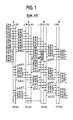
- Fig. 1 shows a packet transfer sequence effected between end terminals according to a prior art packet switched communications system.
- character L represents the execution of flow control and retransmission control on a link-by-link basis
- L(S) indicates a transmission execution
- L(R) indicates a reception execution.
- Character N represents a packet switching operation by means of which a route is determined for each packet.
- D#n represents the packet and ACK(L) and ACK#n represent link-by-link acknowledgement and end-to-end acknowledgement, respectively.
- RGJ(L)#n represents a request for retransmission between links and ERR indicates that a packet has been affected by an error during transmission.
- the number of frames which can be continuously transmitted between switching offices, or "nodes" and the number of frames which can be continuously transmitted between end users are both assumed to be "8". Since no acknowledgment ACK is returned to packets D#0 to D#14 generated by a terminal PT(A) and eight packets can be continuously retransmitted, the first eight packets D#0 through D#7 are allowed entry to the network. Acknowledgement ACK(L) is returned at each link and acknowlegement ACK#n is returned to the source terminal to indicate that the destination terminal has correctly received packets D#0 through D#n.
- the amount of processing time at each node is substantial particularly when speech signal is transmitted. Because of the redundancy of information in the speech signal, no retransmission is required even if packets are noise affected at low frequency. Although buffer overflow in an interface node can be avoided, it is impossible to directly restrict the traffic at the entry point of the network when overflow occurs in an intermediate node. As a result, the traffic congestion in an intermediate node is likely to migrate to neighboring nodes.
- US-A-4 475 192 discloses a data packet flow control scheme using virtual circuits in a multinode packet switching network.
- a packet flow control scheme using virtual circuits in a multinode packet switching network.
- In order to avoid buffer congestion count is maintained of packets presently stored in and being processed through the node. If the count exceeds a predetermined threshold, a packet cannot get an authorisation to enter the node unless it has a credit to leave.
- This system provides an overload control and implements protocol functions including error correction and flow control on an end-to-end and application-dependent basis.
- PROCEEDINGS OF THE FOURTH INTERNATIONAL CONFERENCE ON COMPUTER COMMUNICATION Kyoto, 26th. to 29th September 1978, North-Holland Publishing Company, The Netherlands, I. Takenaka et al: "Evaluation of flow control schemes for packet switched network" a packet switched network is described with high level data linked control procedures. Receive not ready frames are used to inform the neighbouring nodes of a temporary inability to receive information frames.
- the communications system includes a plurality of switching nodes for serving a plurality of terminals through transmission links.
- Each of said terminals transmits a packet of data link layer control protocol including a network layer control protocol to one of said switching nodes.
- Each of the switching nodes comprises means responsive to the network control protocol of the packet for routing the packet to one of the transmisssion links defined by the network layer control protocol of the packet.
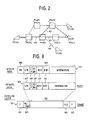
- a virtual-circuit packet-switched communications system embodying the present invention is shown in Fig. 2.
- the communications system comprises a plurality of packet switching offices or "nodes” PS and end users or “terminals” PT(A), PT(B) and PT(C) which terminate at interface nodes PS(A), PS(B) and PS(C), respectively.
- the terminal PT(C) is shown as having an alternate transmission link to the interface node PS(D).
- the transmission capacity is assigned on an "as needed" basis, but all packets of a mutipacket message follow the same route through the network.
- a route is established through the network in response to a call-establishing control packet, and all participating nodes are informed of the connection and how to route the individual packets that follow.
- the route so established is a virtual circuit, or "logical channel" as is interchangeably used in data communications art.
- a virtual circuit is released by a call-clearing control packet propagating through the network.
- a network-layer packet 105 is transmitted between a terminal and an interface switching node and between adjacent switching nodes in the form of a frame 101 by appending to the network layer packet a data-link layer header field which comprises start and closing flags 102, a receive-ready/receive-not-ready subfield 103 and a frame check sequence 104.
- This data-link layer header is processed by participating switching nodes in the network and the terminals.
- the packet comprises a logical channel number subfield 107, a packet identifier 108 designated "TYP”, a retransmission enable/disable subfield 109 designated "RT/NRT”, and subfields 110 and 111 designated N(S) and N(R), with N(S) indicating the sequence number of packets sent on a common logical channel from a source node and N(R) indicating the sequence number of packets sent to the source node from a receiving node.
- the packet identifier identifies a packet with a particular characterization including control, message, traffic congestion (CONG), congestion-free (FREE), acknowledgment (ACK), and retransmission request (REJ).
- CONG traffic congestion
- FREE congestion-free
- ACK acknowledgment
- REJ retransmission request
- the subfield RT/NRT with a binary "0” enables the retransmission request packet (REJ) to be transmitted and with a binary "1" indicating the disablement of the retransmission packet.
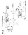
- each packet switching node comprises a central processor 1, a plurality of line controllers 2 to which associated end users or adjacent nodes are connected by way of transmission links 3 which may be four-wire lines or full-duplex facilites.
- Each line controller 2 operates as an incoming line controller or an outgoing line controller.
- a control packet is transferred from an incoming line controller through a control bus 6 to the central processor 1 where it is processed and transferred to an outgoing line controller whenever a connection is set up or released.
- Central processor 1 stores routing information regarding the incoming and outgoing route numbers and incoming and outgoing logical channel numbers whenever a connection is established by address data contained in the control packet. Message packets are transferred between incoming and outgoing line controllers 2 over a data bus 5 under the control of a bus controller 7.
- line controller 2 Details of line controller 2 are shown in Fig. 5.
- controller 2 operates as an incoming line controller
- the link 3 is the incoming route and packets received on link 3 from a source user are passed through a data-link layer controller 10 and a header updating circuit 11 to a receive buffer 14 for transfer to an outgoing line controller 2.
- the line controller operates as an outgoing line controller for transmitting the packets through the data-link layer controller 10 on link 3 to a destination user.
- Header updating circuit 11 has an input from the data-link layer controller 10 to examine the header field of a packet received from the controller 10 and extract the logical channel number from the LCN subfield 107 and the packet identifyer from the TYP subfield 108 of the packet. Updating circuit 11 uses the extracted data as an address to access a switching control memory 12 which is updated by a memory controller 13 with routing information supplied from the central processor 1 in response to the establishment of a connection by each of the line controllers 2. During the period following a call setup, the data read out of the memory 12 by the header updating circuit 11 indicates the outgoing route number RN and outgoing logical channel number LCN.
- Updating circuit 11 inserts the outgoing route number to a subfield 106 of a message packet and the outgoing logical channel number into the LCN subfield of the packet so that it appears as shown at 112 in Fig. 3 at the input of the receive buffer 14. If the packet is a control packet, the logical channel number of the packet remains unchanged and the outgoing route number is updated such that the control packet is routed to the central processor 1 through receive buffer 14 and an interface 15. The updated message packet is routed to an outgoing line controller identfied by the outgoing route number and logical channel number indicated by the header field of the message packet.
- Receive buffer 14 has a control input from the switching and overflow control memory 12 to receive a node overflow signal and a control output leading to the data-link layer controller 10 to supply to it a buffer-overflow signal (RNR).
- the receive buffer 14 includes a memory 140 having a data input terminal connected to the output of the header updating circuit 11 and an output terminal connected to the bus interface 15.
- An address controller 141 controls the memory 140 with write and read enable signals at proper timing in response to a system clock under normal conditions and examines the storage level of the memory 140 to generate the buffer overflow signal when it is filled with more than normal packets. Address controller 141 responds to the node overflow signal by disabling the read/write operation.
- Transmit buffer 16 has a control input connected from the data-link layer controller 10 to receive a hald-and-discard signal and a control output leading to the controller 13 to supply to it a transmit buffer overflow signal.
- the transmit buffer 16 includes a memory 160 having a data input terminal connected to the bus interface 15 and an output terminal connected to the data-link layer controller 10.
- An address controller 161 controls the memory 160 with write and read enable signals at proper timing in response to a system clock under normal conditions and examines the storage level of the memory 160 to generate the transmit buffer overflow signal when it is filled with more than normal packets. Address controller 161 responds to the halt-and-discard signal by disabling the read/write operation.
- the data-link layer controller 10 provides data-link layer process by detecting start and closing flags, a frame check sequence and an RR/RNR subfield in a packet received through a line interface 20 and by appending such data-link layer subfields to a packet to be sent through the interface 20.
- a framing circuit 21, an FCS error detector 22 and an RR/RNR (receive-ready/ receive-not-ready) detector 23 are connected in a series circuit from the interface 20 and the header updating circuit 11.
- An RR/RNR generator 24, an FCS generator and a framing circuit 26 are connected in series from the output of transmit buffer 16 and the line interface 20 to provide the data-link-layer process.
- the RR/RNR detector 23 applies an output signal to a link overflow controller 27 when the RR/RNR subfield indicates that a "receive-not-ready" condition, or traffic overflow has occurred in an adjacent node.
- the function of the link overflow controller 27 includes the detection of the presence of a "receive-not-ready" signal returned from the adjacent node, the detection of its continuity exceeding a predetermined time interval and the application of a link-overflow signal to the controller 13. This is to allow an intermediate switching node to determine the source terminal and send to it a congestion (CONG) signal to prevent the outgoing traffic at entry point of the network in order to reduce the volume of traffic from an intermediate node to an adjacent node.
- CONG congestion
- link overflow controller 27 causes the transmit buffer 16 to stop sending packets to the source terminal.
- controller 27 causes buffer 16 to discard the first of packets that form a queue in the buffer 16 waiting to be served.
- link overflow controller 14 has an input from the receive buffer 14 to respond to a "buffer overflow" signal by enabling the RR/RNR generator 24 to reduce the amount of traffic from the adjacent node or terminal by indicating that a receive buffer is overflowd.
- the RR/RNR generator 24 operates when the traffic in the opposite direction is overflowed.
- the switching control memory 12 comprises a call setup table 30, an outgoing route table 31, an incoming route table 32 and an overflow control table 33.
- the outgoing and incoming route tables 31 and 32 are updated by the memory controller 13 by way of the central processor 1.
- the call setup table 30 stores an outgoing route number (which is permanently indicative of the address of the central processor 1) in a storage location addressable as a function of the packet identifier (TYP) and incoming logical channel number (ILCN) subfields of a control packet together with the incoming route number (IRN) which identifies the line controller handling the control packet (see Fig. 12A).
- the outgoing route table 31 stores a set of outgoing route number (ORN) and outgoing logical channel number (OLCN) in a location addressable as a function of the incoming route number (IRN) and incoming logical channel number (ILCN) subfields of a message packet (Fig. 12B).
- Header updating circuit 11 accesses the outgoing route table 31 to update the incoming logical channel number (ILCN) of a message packet and append to it the outgoing route number to direct the message packet to an outgoing line controller.
- Incoming route table 32 stores a set of incoming route number (IRN), incoming logical channel number (ILCN) and the address of a source terminal (PT) into a location addressable as a function of the outgoing route number (ORN) and outgoing logical channel number (OLCN) subfields of either control or message packet (Fig. 12C).
- IRN incoming route number
- ILCN incoming logical channel number
- ORN outgoing route number
- OLCN outgoing logical channel number
- Overflow control table 33 stores overflow control data as shown in Fig. 12D which indicates the traffic conditions of outgoing routes. This table is used by incoming-mode line controllers to determine whether the outgoing route for an incoming logical channel number is overflowed or not whenever it receives a packet.
- Table 33 is updated under control of the memory controller 13 of the incoming line controller when it is informed of an incoming logical channel number by an outgoing line controller 2 of which the outgoing route is overflowed. This occurs in response to the generation of an overflow signal by the transmit buffer 16 of the outgoing line controller when the storage level of the buffer 16 exceeds a predetermined value.
- the memory controller 13 of this line controller communicates this fact to the incoming line controller or controllers that extend their incoming logical channels through the overflowed outgoing route.
- the overflow control table 33 of each incoming line controller is accessed by the header updating circuit 11 as a function of the incoming logical channel number of a packet it receives to control its traffic if it passes through the overflowed outgoing route.
- the transmit buffer 16 of the outgoing line controller notifies this fact to the incoming line controller or controllers to cause them to update their overflow control table 33 accordingly.
- Header updating circuit 11 is shown in detail in Fig. 8.
- This circuit comprises a timing circuit 40 that supplies timing signals to latches 41, 42 and 43 and to a multiplexer 44, and a shift register 45.
- Incoming packets from data-link layer controller 10 are applied to latch 41 and shift register 45.
- Latch 45 extracts the logical channel number and packet identifier for coupling to switching control memory 12 in response to a timing pulse from the timing circuit 40.
- the outgoing route number and outgoing logical channel number from the switching control memory 12 are stored into latches 42 and 43.
- Multiplexer 44 is properly timed to multiplex the outputs of latches 42 and 43 with the output of shift register 45, whereby the logical channel number subfield of the packet is updated and the outgoing route number subfield is appended to the packet for it to be processed within the switching node.
- Central processor 1 shown in Fig. 11, comprises a central processing unit 50 which determines the outgoing logical channel number in accordance with the address of the destination terminal contained in a control packet it receives from an incoming line controller by way of data bus 5, data bus inerface 52 and receive buffer 53.
- Central prcessing unit 50 determines the outgoing route number of the control packet and appends it to the control packet.
- a control-packet header updating circuit 51 updates the logical channel number subfield of the control packet with the outgoing logical channel number determined by the CPU 50.
- the control packet with the LCN subfield updated and an outgoing route number being appended thereto is sent through transmit buffer 54, interface 52 and data bus 5 to the line controller 2 specified by the outgoing route number.
- a memory 55 serves an aid for the CPU 50 to process control packets and stores the routing information of each packet in response to the establishment of a connection.
- the routing information is also transferred through a bus interface 56 and control bus 6 to all the line controllers 2 to update their outgoing and incoming route tables 31 and 32.
- a routing table 57 which is used to determine an outgoing route for leach call or an alternate route when link overflow is encoutered on the initial route.
- a call setup procedure is initiated upon arrival of a call-establishing control packet of a multi-packet message at the data-link layer controller 10 of an incoming line controller through the transmission link 3.
- the control packet is supplied to the header updating circuit 11, Fig. 8.
- the logical channel number LCN and the packet identifier TYP of the control packet are sent from latch 41 to the outgoing route trable 30 of switching control memory 12.
- the outgoing route is permanently fixed to "0" which causes the control packet to be transferred to the central processor 1.
- An outgoing logical channel number and an outgoing route number are determined by the central processor in accordance with the address of a sink terminal indicated by the control packet to subsequently transfer the control packet to the desired outgoing route.
- Central processor 1 proceeds to rewrite the outgoing route table 31 of the incoming line controller 2 with the determined outgoing logical channel number and outgoing route number and rewrite the incoming route table 32 of the outgoing line controller 2 with the incoming route number and incoming logical channel number.
- the header updating circuit 51 of central processor 1 updates the logical channel number subfield of the control packet and appends the determined outgoing route number to it as a new subfield forming a packet 112 as shown in Fig. 2 and sends it to the outgoing line controller of the determined route.
- Controller 10 After the connection is established, message packets, either data or voice, are sequentially supplied to the data-link layer controller 10. Controller 10 provides the same data-link layer control on message packets as it does on the control packet. Header updating circuit 11 extracts the incoming logical channel number and packet identifier from the message packet it received from controller 10 and utilizes the extracted data to look up the outgoing route table 31 of the switching control memory 12 to read out the outgoing logical channel number (OLCN) and outgoing route number (ORN) which have been established by the preceding control packet.
- OLCN outgoing logical channel number
- ORN outgoing route number
- the LCN subfield of the message packet is updated with the LCN data read out of the outgoing route table 31 and the RN data is appended to it as a new subfield by the header updating circuit 11 for routing it to a desired outgoing link, as mentioned previously. All the message packet thus follow the same route as established by the control packet.
- a call-clearing control packet is sent from the source terminal and is treated so that the stored outgoing and incoming routing information relating to the connection are erased.
- control packets and message packets are handled respectively by the central processor for call-establishment and call-clearing procedures and by individual line controllers without seeking assistance to the central processor using separate control and data buses.
- the separation of the switching functions and the separation of the switching network into control and message handling subnetworks result in a packet switching system capable of operating at a significantly high speed and high throughput.
- the header updating circuit 11 of each line controller accesses the overflow control table 33 as well as to call setup or outgoing route table in order to check for the presence of an overflow traffic on the desired outgoing route.
- overflow control table 33 supplies a "discard" instruction to the receive buffer 14 (see Fig. 7). Packets destined to the outgoing route ORN2 are therefore denied entry to the receive buffer of line controller 2-1 to prevent it from becoming overflowed with long-waiting packets, allowing packets destined to the outgoing route ORN1 to be passed to the receive buffer of line controller 2-2.
- switching nodes PS(A) and PS(B) are participating in a connection between source and sink terminals as schematically illustrated in Fig. 14 and the traffic from node PS(A) to node PS(B) is overflowed at the entry to the receive buffer 14 of node PS(B).
- an overflow signal is supplied from the receive buffer 14 to the link overflow controller 27, which causes the RR/RNR generator 24 to update the RR/RNR (receive-ready/receive-not-ready) subfield of a packet from the transmit buffer 16 so that it signifies that the node PS(B) is not ready to receive traffic from node PS(A).
- the updated packet is sent to a line controller 2a of node PS(A) where it is received by the RR/RNR detector 23 of data-link layer controller 10, Fig. 6.
- Detector 23 provides an output to the link overflow controller 27, which starts monitoring the continuity of such overflow condition and supplies a halt-and-discard signal to the transmit buffer 16 if such a condition continues over a predetermined time interval and sends an overflow signal to the memory controller 13.
- the outgoing line controller 2a stops sending packets to the switching node PS(B). If the storage level of transmit buffer 16 of line controller 2a reaches a predetermined value following the cessation of transmission, transmit buffer 16 discards the overflowed packets.
- the memory controller 13 of the outgoing line controller 2a Upon receipt of the overflow signal from the overflow controller 27, the memory controller 13 of the outgoing line controller 2a looks up the incoming route table 32 to read the incoming routing information including a source terminal address as well as incoming route number and incoming logical channel number and sends the retrieved incoming route information as well as the outgoing routing information to the central processor 1.
- Central processor 1 rejects the establishment of a call through the overflowed outgoing route now informed by the outgoing line controller 2a when it receives a call-establishing control packet that is destined to the overflowed route. At the same time, the central processor 1 uses the incoming route number to identify the incoming line controller 2b and proceeds to generate a congestion packet (CONG) and transmits it to the source terminal through the incoming line controller 2b.
- CONG congestion packet
- the source terminal PT(A) Upon receipt of a congestion packet, the source terminal PT(A) stops sending packets. If the congestion is relieved, the central processor of the switching node PS(A) sends a congestion-free (FREE) packet to the source terminal PT(A). If the congestion-free packet is received within a predetermined time interval, the terminal PT(A) reinitiates transmission of packets. However, if the congestion-free packet is not received within the predetermined time interval, the terminal PT(A) sends a control packet requesting the reestablishment of a connection through an alternate transmission link.
- FREE congestion-free
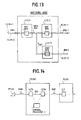
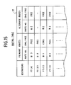
- Fig. 15 illustrates the contents of the routing table 57 of central processor 1 in respect of a switching node PS(B) in the network of Fig. 1.
- Switching node PS(B) has primary routes and alternate routes. With resect to the priorty route, the switching node PS(B) has outgoing routes #3, #0, #1 and #2 for terminal destinations PT(A), PT(B), PT(C) and PT(D), respectively.
- the alternate routes available for switching node PS(B) are route #2 for destinations PT(A) and PT(C) and route #3 for destination PT(D).
- Fig. 1 it is assumed that a connection is established between terminals PT(A) and PT(C) with nodes PS(A), PS(B) and PS(C) participating in the connection.
- the central processor 1 of switching node PS(B) updates the routing table 57 so that a congestion indication is given to the route #1 with the other routes being given a congestion-free indication.
- congestion-free indications are initially given to all the routes available for alternate routing.
- the central processor of the switching node PS(B) accesses the routing table 57 to find an alternate route.
- the route #2 to switching node PS(D) is selected to reestablish a connection between the node PS(B) and terminal PT(C).
- the terminal sends a call-disconnect request packet to the switching node PS(S) to clear the route #1.
- the central processor sends a call-establishing control packet to the switching node PS(D) over the alternate route #2.
- the present invention provides a high speed, high throughput packet-switched communications system by end-to-end flow control and packet retransmission by eliminating the prior art link-by-link method of flow control and packet transmission.
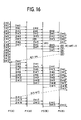
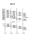
- Figs. 16 and 17 are illustrations of end-to-end packet transfer sequences according to the present invention.
- Fig. 16 illustrates packet transfer sequences in which packets D#0 through D#14 are generated sequentially by a terminal and an FCS error occurs in packet D#4 during transmission between nodes PS(A) and PS(B) as in Fig. 1.
- FCS error occurs in packet D#4 during transmission between nodes PS(A) and PS(B) as in Fig. 1.
- destination terminal PT(B) receives a packet D#5, it recognizes that packet D#4 contains an error and sends a retransmission request REJ#4 to the source terminal PT(A) by writing a binary "0" into the RT/NRT field.
- Retransmission begins with packet D#4 and ends with packet D#11.
- Retransmission may be initiated upon the receipt of packet REJ#n or in response to a time out operation. For example, if a packet D#0 is received but no acknowledgment is received within a preset period of time from the node PT(B), node PS(A) retransmits packet D#0.
- Fig. 17 is an illustration of sequences in which the RT/RNT subfield of the received packet is "1" indicating that retransmission of REJ packets is disabled. It is assumed that the receive buffer of destination node PS(B) is congested when it receives packet D#3 and node PS(B) returns an RNR frame to source node PS(A). Fig. 17 shows that the source node PS(A) forcibly discards packets D#4 and D#5. Upon the termination of the overflow of receive buffer of destination node PS(B), an RR frame is returned to the source node to allow retransmission of packets D#6 and D#7.
- the destination terminal PT(B) detects a sequence error in packets D#4 and D#5 and an acknowledgment ACK#7 is returned. Thus, the retransmission of packets D#6 through D#10 does not result in an increase in the propagation delay.
- the present invention eliminates the need for acknowledgment and retransmission on a link-by-link basis with respect to message packets and causes the source and destination terminals to perform compensation for packets lost in the network due to overflows or bit errors, whereby the packet switching operation performed by each node and hence the processing time is significantly reduced and the throughput of a node is increased.
- the traffic control at an entry point of the network effectively avoids a networkwide traffic congestion.
Landscapes
- Engineering & Computer Science (AREA)
- Computer Networks & Wireless Communication (AREA)
- Signal Processing (AREA)
- Data Exchanges In Wide-Area Networks (AREA)
Description
- The present invention relates to a packet-switched communications system which is capable of high speed, high throughput switching operations to handle a variety of traffic patterns by efficient utilization of system resources.
- According to a prior art packet switched communications system, flow control with a higher-level data link control and error recovery retransmission control are effected on a link-by-link throughout the network. These techniques are needed because the transmission speed of the prior art packet switching system is low, typically in the range between several Kbps and several tens of Kbps and the bit error rate is relatively high. Since these techniques involve a large number of complicated procedures, they require a lengthy period execution time. In addition, the execution of such procedures must be repeated at locations where packets are retransmitted over the network, resulting in packets arriving at delayed times.
- The introduction of optical fibers as a high speed high quality transmission medium allows reduction of packet transmission delay. However, the amount of delay involved in the execution of link-by-link flow control and retransmission is becoming a dominant factor of the total delay time. On the other hand, the frequency at which the retransmission process must be effected has decreased significantly with the reduction of transmission bit error rate and the control overhead for link-by-link retransmission increases significantly. As a result, a high speed, high throughput packet switched communications system cannot be implemented with the introduction of high speed, high quality transmission media without improvement of the switching speed of the packet switching system,
- More specifically, Fig. 1 shows a packet transfer sequence effected between end terminals according to a prior art packet switched communications system. In Fig. 1, character L represents the execution of flow control and retransmission control on a link-by-link basis, L(S) indicates a transmission execution and L(R) indicates a reception execution. Character N represents a packet switching operation by means of which a route is determined for each packet. D#n represents the packet and ACK(L) and ACK#n represent link-by-link acknowledgement and end-to-end acknowledgement, respectively. RGJ(L)#n represents a request for retransmission between links and ERR indicates that a packet has been affected by an error during transmission. The number of frames which can be continuously transmitted between switching offices, or "nodes" and the number of frames which can be continuously transmitted between end users are both assumed to be "8". Since no acknowledgment ACK is returned to
packets D# 0 toD# 14 generated by a terminal PT(A) and eight packets can be continuously retransmitted, the first eightpackets D# 0 throughD# 7 are allowed entry to the network. Acknowledgement ACK(L) is returned at each link and acknowlegement ACK#n is returned to the source terminal to indicate that the destination terminal has correctly receivedpackets D# 0 through D#n. Assume that an error has occurred inpacket D# 4 during transmission between nodes PS(A) and PS(B) and node PS(B) returns a request for retransmission REJ(L)#4 to node PS(A) and the latter retransmitspackets D# 4 throughD# 7 to node PS(B). When acknowledgment ACK#4 is returned to source terminal PT(A), the remaining four data packets are allowed entry to the network. - As can be seen from Fig. 1, the amount of processing time at each node is substantial particularly when speech signal is transmitted. Because of the redundancy of information in the speech signal, no retransmission is required even if packets are noise affected at low frequency. Although buffer overflow in an interface node can be avoided, it is impossible to directly restrict the traffic at the entry point of the network when overflow occurs in an intermediate node. As a result, the traffic congestion in an intermediate node is likely to migrate to neighboring nodes.
- US-A-4 475 192 discloses a data packet flow control scheme using virtual circuits in a multinode packet switching network. In order to avoid buffer congestion count is maintained of packets presently stored in and being processed through the node. If the count exceeds a predetermined threshold, a packet cannot get an authorisation to enter the node unless it has a credit to leave. In PROCEEDINGS OF THE NINTH DATA COMMUNICATIONS SYMPOSIUM of 10th to 13th. September 1985, pages 124 to 133, IEEE, New York, J.S. Turner: "Design of an integrated services packet network", an ISDN SYSTEM has been proposed for providing integrated voice and data communications services. This system provides an overload control and implements protocol functions including error correction and flow control on an end-to-end and application-dependent basis. In PROCEEDINGS OF THE FOURTH INTERNATIONAL CONFERENCE ON COMPUTER COMMUNICATION, Kyoto, 26th. to 29th September 1978, North-Holland Publishing Company, The Netherlands, I. Takenaka et al: "Evaluation of flow control schemes for packet switched network" a packet switched network is described with high level data linked control procedures. Receive not ready frames are used to inform the neighbouring nodes of a temporary inability to receive information frames.
- It is therefore an object of the present invention to provide a high-speed packet switched communications system and a high-speed packet switching system incorporated in the communications system to serve as a switching node.
- The foregoing problems are eliminated by the packet switched communications system of the invention by the employment of end-to-end flow control and retransmission instead of the link-to-link method of flow control and retransmission.
- The communications system includes a plurality of switching nodes for serving a plurality of terminals through transmission links. Each of said terminals transmits a packet of data link layer control protocol including a network layer control protocol to one of said switching nodes. Each of the switching nodes comprises means responsive to the network control protocol of the packet for routing the packet to one of the transmisssion links defined by the network layer control protocol of the packet.
- In particular the above-mentioned object is solved with the features of the claims.
- The invention is further explained in connection with the attached drawings:
- Fig. 1 is an illustration of packet transfer sequences according to the link-by-link method of flow control and retransmission employed in a prior art packet switched communications system;
- Fig. 2 is a schematic illustration of a packet switched communications system embodying the present invention, which is useful for description of the end-to-end flow control and alternate routing operations;
- Fig. 3 is an illustration of a data format according to the present invention;
- Fig. 4 is a block diagram of a packet switching system embodying the present invention;
- Fig. 5 is a block diagram of each of the line controllers of Fig. 4;
- Fig. 6 is a block diagram of the data-link layer controller of Fig. 5;
- Fig. 7 is a block diagram of the switching control memory of Fig. 5;
- Fig. 8 is a block diagram of the header updating circuit of Fig. 5;
- Figs. 9 and 10 are details of the receive buffer and transmit buffer of Fig. 5, respectively;
- Fig. 11 is an illustration of details of the central processor of Fig. 4;
- Figs. 12A, 12B, 12C are illustrations of the contents of the call setup, outgoing route and incoming route tables, respectively, of Fig. 7 and Fig. 12D is an illustration of the contents of the overflow control table of Fig. 7;
- Fig. 13 is a schematic illustration useful for describing the operation of intranode overflow control;
- Fig. 14 is a schematic illustration useful for describing the operation of internode overflow control;
- Fig. 15 is an illustration of the contents of the routing table of Fig. 11; and
- Figs. 16 and 17 are illustrations of packet transfer sequences according to the end-to-end flow control and retransmission of the present invention.
- A virtual-circuit packet-switched communications system embodying the present invention is shown in Fig. 2. The communications system comprises a plurality of packet switching offices or "nodes" PS and end users or "terminals" PT(A), PT(B) and PT(C) which terminate at interface nodes PS(A), PS(B) and PS(C), respectively. For purposes of illustration, the terminal PT(C) is shown as having an alternate transmission link to the interface node PS(D). In the virtual-circuit network, the transmission capacity is assigned on an "as needed" basis, but all packets of a mutipacket message follow the same route through the network. Before interactive communication begins, a route is established through the network in response to a call-establishing control packet, and all participating nodes are informed of the connection and how to route the individual packets that follow. The route so established is a virtual circuit, or "logical channel" as is interchangeably used in data communications art. At the end of a connection, a virtual circuit is released by a call-clearing control packet propagating through the network.
- To eliminate the prior art link-by-link method of flow control to achieve high speed packet switching, frame and packet formats are provided shown in Fig. 3 which respectively correspond to data-link layer and network layer protocols. A network-
layer packet 105 is transmitted between a terminal and an interface switching node and between adjacent switching nodes in the form of aframe 101 by appending to the network layer packet a data-link layer header field which comprises start and closingflags 102, a receive-ready/receive-not-ready subfield 103 and aframe check sequence 104. This data-link layer header is processed by participating switching nodes in the network and the terminals. The packet comprises a logicalchannel number subfield 107, apacket identifier 108 designated "TYP", a retransmission enable/disablesubfield 109 designated "RT/NRT", and subfields 110 and 111 designated N(S) and N(R), with N(S) indicating the sequence number of packets sent on a common logical channel from a source node and N(R) indicating the sequence number of packets sent to the source node from a receiving node. - The packet identifier identifies a packet with a particular characterization including control, message, traffic congestion (CONG), congestion-free (FREE), acknowledgment (ACK), and retransmission request (REJ). The subfield RT/NRT with a binary "0" enables the retransmission request packet (REJ) to be transmitted and with a binary "1" indicating the disablement of the retransmission packet.
- As illustrated in Fig. 4, each packet switching node comprises a
central processor 1, a plurality ofline controllers 2 to which associated end users or adjacent nodes are connected by way oftransmission links 3 which may be four-wire lines or full-duplex facilites. Eachline controller 2 operates as an incoming line controller or an outgoing line controller. A control packet is transferred from an incoming line controller through acontrol bus 6 to thecentral processor 1 where it is processed and transferred to an outgoing line controller whenever a connection is set up or released.Central processor 1 stores routing information regarding the incoming and outgoing route numbers and incoming and outgoing logical channel numbers whenever a connection is established by address data contained in the control packet. Message packets are transferred between incoming andoutgoing line controllers 2 over adata bus 5 under the control of abus controller 7. - Details of
line controller 2 are shown in Fig. 5. Whencontroller 2 operates as an incoming line controller, thelink 3 is the incoming route and packets received onlink 3 from a source user are passed through a data-link layer controller 10 and aheader updating circuit 11 to a receivebuffer 14 for transfer to anoutgoing line controller 2. When packets are transferred from an incoming line controller and sequentially stored into the transmitbuffer 16, the line controller operates as an outgoing line controller for transmitting the packets through the data-link layer controller 10 onlink 3 to a destination user. -
Header updating circuit 11 has an input from the data-link layer controller 10 to examine the header field of a packet received from thecontroller 10 and extract the logical channel number from theLCN subfield 107 and the packet identifyer from theTYP subfield 108 of the packet. Updatingcircuit 11 uses the extracted data as an address to access aswitching control memory 12 which is updated by amemory controller 13 with routing information supplied from thecentral processor 1 in response to the establishment of a connection by each of theline controllers 2. During the period following a call setup, the data read out of thememory 12 by theheader updating circuit 11 indicates the outgoing route number RN and outgoing logical channel number LCN. Updatingcircuit 11 inserts the outgoing route number to asubfield 106 of a message packet and the outgoing logical channel number into the LCN subfield of the packet so that it appears as shown at 112 in Fig. 3 at the input of the receivebuffer 14. If the packet is a control packet, the logical channel number of the packet remains unchanged and the outgoing route number is updated such that the control packet is routed to thecentral processor 1 through receivebuffer 14 and aninterface 15. The updated message packet is routed to an outgoing line controller identfied by the outgoing route number and logical channel number indicated by the header field of the message packet. - Receive
buffer 14 has a control input from the switching andoverflow control memory 12 to receive a node overflow signal and a control output leading to the data-link layer controller 10 to supply to it a buffer-overflow signal (RNR). As shown in Fig. 9, the receivebuffer 14 includes amemory 140 having a data input terminal connected to the output of theheader updating circuit 11 and an output terminal connected to thebus interface 15. Anaddress controller 141 controls thememory 140 with write and read enable signals at proper timing in response to a system clock under normal conditions and examines the storage level of thememory 140 to generate the buffer overflow signal when it is filled with more than normal packets.Address controller 141 responds to the node overflow signal by disabling the read/write operation. - Transmit
buffer 16 has a control input connected from the data-link layer controller 10 to receive a hald-and-discard signal and a control output leading to thecontroller 13 to supply to it a transmit buffer overflow signal. As shown in Fig. 10, the transmitbuffer 16 includes amemory 160 having a data input terminal connected to thebus interface 15 and an output terminal connected to the data-link layer controller 10. Anaddress controller 161 controls thememory 160 with write and read enable signals at proper timing in response to a system clock under normal conditions and examines the storage level of thememory 160 to generate the transmit buffer overflow signal when it is filled with more than normal packets.Address controller 161 responds to the halt-and-discard signal by disabling the read/write operation. - Specifically, in Fig. 6, the data-
link layer controller 10 provides data-link layer process by detecting start and closing flags, a frame check sequence and an RR/RNR subfield in a packet received through aline interface 20 and by appending such data-link layer subfields to a packet to be sent through theinterface 20. To this end, a framingcircuit 21, an FCS error detector 22 and an RR/RNR (receive-ready/ receive-not-ready)detector 23 are connected in a series circuit from theinterface 20 and theheader updating circuit 11. An RR/RNR generator 24, an FCS generator and a framingcircuit 26 are connected in series from the output of transmitbuffer 16 and theline interface 20 to provide the data-link-layer process. The RR/RNR detector 23 applies an output signal to alink overflow controller 27 when the RR/RNR subfield indicates that a "receive-not-ready" condition, or traffic overflow has occurred in an adjacent node. - The function of the
link overflow controller 27 includes the detection of the presence of a "receive-not-ready" signal returned from the adjacent node, the detection of its continuity exceeding a predetermined time interval and the application of a link-overflow signal to thecontroller 13. This is to allow an intermediate switching node to determine the source terminal and send to it a congestion (CONG) signal to prevent the outgoing traffic at entry point of the network in order to reduce the volume of traffic from an intermediate node to an adjacent node. At the same time, linkoverflow controller 27 causes the transmitbuffer 16 to stop sending packets to the source terminal. If the storage level of thebuffer 16 exceeds a predetermined value as a result of the cessation of packet transmission,controller 27causes buffer 16 to discard the first of packets that form a queue in thebuffer 16 waiting to be served. Further, linkoverflow controller 14 has an input from the receivebuffer 14 to respond to a "buffer overflow" signal by enabling the RR/RNR generator 24 to reduce the amount of traffic from the adjacent node or terminal by indicating that a receive buffer is overflowd. The RR/RNR generator 24 operates when the traffic in the opposite direction is overflowed. - In Fig. 7, the switching
control memory 12 comprises a call setup table 30, an outgoing route table 31, an incoming route table 32 and an overflow control table 33. The outgoing and incoming route tables 31 and 32 are updated by thememory controller 13 by way of thecentral processor 1. More specifically, the call setup table 30 stores an outgoing route number (which is permanently indicative of the address of the central processor 1) in a storage location addressable as a function of the packet identifier (TYP) and incoming logical channel number (ILCN) subfields of a control packet together with the incoming route number (IRN) which identifies the line controller handling the control packet (see Fig. 12A). During call setup phase, the call setup table 30 is accessed by theheader updating circuit 11 to direct it to thecentral processor 1 where it is processed for call establishment in a manner as will be described later. The outgoing route table 31 stores a set of outgoing route number (ORN) and outgoing logical channel number (OLCN) in a location addressable as a function of the incoming route number (IRN) and incoming logical channel number (ILCN) subfields of a message packet (Fig. 12B).Header updating circuit 11 accesses the outgoing route table 31 to update the incoming logical channel number (ILCN) of a message packet and append to it the outgoing route number to direct the message packet to an outgoing line controller. Incoming route table 32 stores a set of incoming route number (IRN), incoming logical channel number (ILCN) and the address of a source terminal (PT) into a location addressable as a function of the outgoing route number (ORN) and outgoing logical channel number (OLCN) subfields of either control or message packet (Fig. 12C). During a read mode, the incoming route table 32 is accessed by thecontroller 13 to read out the stored incoming routing data and source terminal address to provide traffic control. - It is to be noted that there is a one-to-one correspondence between the outgoing and incoming route tables 31 and 32 except for the source terminal address so that a set of incoming route number and incoming logical number can be determined by a set of outgoing route number and outgoing logical channel number, and vice versa. This permits the
memory controller 13 to obtain routing information as to the source terminal to impose access restriction at the entry of the network. - Overflow control table 33 stores overflow control data as shown in Fig. 12D which indicates the traffic conditions of outgoing routes. This table is used by incoming-mode line controllers to determine whether the outgoing route for an incoming logical channel number is overflowed or not whenever it receives a packet.
- Table 33 is updated under control of the
memory controller 13 of the incoming line controller when it is informed of an incoming logical channel number by anoutgoing line controller 2 of which the outgoing route is overflowed. This occurs in response to the generation of an overflow signal by the transmitbuffer 16 of the outgoing line controller when the storage level of thebuffer 16 exceeds a predetermined value. - Specifically, when the transmit
buffer 16 of a givenoutgoing line controller 2 is overflowed, thememory controller 13 of this line controller communicates this fact to the incoming line controller or controllers that extend their incoming logical channels through the overflowed outgoing route. - The determination of the incoming line controller or controllers by the outgoing line controller is accomplished by use of its incoming route table 32 by the
memory controller 13. For example, incoming route table 32, Fig. 12C, indicates that an incoming logical channel ILCN=0 is passing through an outgoing route ORN2 on an outgoing logical channel OLCN=1. ILCN=0 is used by the incoming line controller to access the overflow control table 33 to update the storage location of ILCN=0 with a congestion signal CONG. As will be described later, the overflow control table 33 of each incoming line controller is accessed by theheader updating circuit 11 as a function of the incoming logical channel number of a packet it receives to control its traffic if it passes through the overflowed outgoing route. - When the traffic congestion is relieved, the transmit
buffer 16 of the outgoing line controller notifies this fact to the incoming line controller or controllers to cause them to update their overflow control table 33 accordingly. -
Header updating circuit 11 is shown in detail in Fig. 8. This circuit comprises a timing circuit 40 that supplies timing signals tolatches multiplexer 44, and ashift register 45. Incoming packets from data-link layer controller 10 are applied to latch 41 andshift register 45.Latch 45 extracts the logical channel number and packet identifier for coupling to switchingcontrol memory 12 in response to a timing pulse from the timing circuit 40. The outgoing route number and outgoing logical channel number from the switchingcontrol memory 12 are stored intolatches Multiplexer 44 is properly timed to multiplex the outputs oflatches shift register 45, whereby the logical channel number subfield of the packet is updated and the outgoing route number subfield is appended to the packet for it to be processed within the switching node. -
Central processor 1, shown in Fig. 11, comprises acentral processing unit 50 which determines the outgoing logical channel number in accordance with the address of the destination terminal contained in a control packet it receives from an incoming line controller by way ofdata bus 5,data bus inerface 52 and receivebuffer 53.Central prcessing unit 50 determines the outgoing route number of the control packet and appends it to the control packet. A control-packetheader updating circuit 51 updates the logical channel number subfield of the control packet with the outgoing logical channel number determined by theCPU 50. The control packet with the LCN subfield updated and an outgoing route number being appended thereto is sent through transmitbuffer 54,interface 52 anddata bus 5 to theline controller 2 specified by the outgoing route number. Amemory 55 serves an aid for theCPU 50 to process control packets and stores the routing information of each packet in response to the establishment of a connection. The routing information is also transferred through abus interface 56 andcontrol bus 6 to all theline controllers 2 to update their outgoing and incoming route tables 31 and 32. Further included in thecentral processor 1 is a routing table 57 which is used to determine an outgoing route for leach call or an alternate route when link overflow is encoutered on the initial route. - A call setup procedure is initiated upon arrival of a call-establishing control packet of a multi-packet message at the data-
link layer controller 10 of an incoming line controller through thetransmission link 3. Following the processing of data-link layer control including framing, frame-check-sequence error detection, and RR/RNR detection, the control packet is supplied to theheader updating circuit 11, Fig. 8. The logical channel number LCN and the packet identifier TYP of the control packet are sent fromlatch 41 to theoutgoing route trable 30 of switchingcontrol memory 12. As illustrated in Fig. 12A, the outgoing route is permanently fixed to "0" which causes the control packet to be transferred to thecentral processor 1. An outgoing logical channel number and an outgoing route number are determined by the central processor in accordance with the address of a sink terminal indicated by the control packet to subsequently transfer the control packet to the desired outgoing route.Central processor 1 proceeds to rewrite the outgoing route table 31 of theincoming line controller 2 with the determined outgoing logical channel number and outgoing route number and rewrite the incoming route table 32 of theoutgoing line controller 2 with the incoming route number and incoming logical channel number. Simultaneously, theheader updating circuit 51 ofcentral processor 1 updates the logical channel number subfield of the control packet and appends the determined outgoing route number to it as a new subfield forming apacket 112 as shown in Fig. 2 and sends it to the outgoing line controller of the determined route. - After the connection is established, message packets, either data or voice, are sequentially supplied to the data-
link layer controller 10.Controller 10 provides the same data-link layer control on message packets as it does on the control packet.Header updating circuit 11 extracts the incoming logical channel number and packet identifier from the message packet it received fromcontroller 10 and utilizes the extracted data to look up the outgoing route table 31 of the switchingcontrol memory 12 to read out the outgoing logical channel number (OLCN) and outgoing route number (ORN) which have been established by the preceding control packet. The LCN subfield of the message packet is updated with the LCN data read out of the outgoing route table 31 and the RN data is appended to it as a new subfield by theheader updating circuit 11 for routing it to a desired outgoing link, as mentioned previously. All the message packet thus follow the same route as established by the control packet. - When a connection is to be released, a call-clearing control packet is sent from the source terminal and is treated so that the stored outgoing and incoming routing information relating to the connection are erased.
- As can be seen from the above that according to the present invention control packets and message packets are are handled respectively by the central processor for call-establishment and call-clearing procedures and by individual line controllers without seeking assistance to the central processor using separate control and data buses. The separation of the switching functions and the separation of the switching network into control and message handling subnetworks result in a packet switching system capable of operating at a significantly high speed and high throughput.
- During the call setup and subsequent packet switching phases, the
header updating circuit 11 of each line controller accesses the overflow control table 33 as well as to call setup or outgoing route table in order to check for the presence of an overflow traffic on the desired outgoing route. - Referring to Fig. 13, it is assumed that an incoming link identified by route number IRN1 is connected through a line controller 2-1 through data bus to line controllers 2-2 and 2-3 to establish virtual circuits identified by incoming logical channel numbers ILCN=1, ILCN=2, a common incoming route number IRN1, outgoing logical channel numbers OLCN1, OLCN2 and outgoing routes ORN1, ORN2, as illustrated. If the outgoing route ORN2 and hence the transmit
buffer 16 of line controller 2-3 is overflowed. Transmitbuffer 16 of the outgoing line controller now sends an overflow signal to itsmemory controller 13. In response to this overflow signal, thememory controller 13 accesses the incoming route table 32 to determine which incoming line controller or controllers the overflow traffic is to be communicated. This is done by accessing the incoming route number IRN1 and incoming logical channel number ILCN=2 of the incoming route table 32 as a function of the outgoing route number ORN2.Memory controller 13 informs the incoming logical channel number ILCN=2 throughcontrol bus 6 to thememory controller 13 of incoming line controller 2-1 identified by the incoming route number IRN1 to allow it to update its overflow control table 33 by rewriting the memory location of the incoming logical channel ILCN=2 with a congestion (CONG) signal. As a result, when the line controller 2-1 receives a packet, itsheader updating circuit 11 accesses the overflow control table 33 as a function of the incoming logical channel number subfield of the packet. If the logical channel number of the packet is ILCN=2, overflow control table 33 supplies a "discard" instruction to the receive buffer 14 (see Fig. 7). Packets destined to the outgoing route ORN2 are therefore denied entry to the receive buffer of line controller 2-1 to prevent it from becoming overflowed with long-waiting packets, allowing packets destined to the outgoing route ORN1 to be passed to the receive buffer of line controller 2-2. - When the overflow condition is relieved, a sequence of events similar to that described above is reinitiated by the transmit buffer of line controller 2-3 with the exception that the line controller 2-1 updates its overflow table 33 with an indication (FREE) that the incoming logical channel ILCN=2 is allowed entry to receive buffer of line controller 2-1.
- Assume that switching nodes PS(A) and PS(B) are participating in a connection between source and sink terminals as schematically illustrated in Fig. 14 and the traffic from node PS(A) to node PS(B) is overflowed at the entry to the receive
buffer 14 of node PS(B). In the switching node PS(B), an overflow signal is supplied from the receivebuffer 14 to thelink overflow controller 27, which causes the RR/RNR generator 24 to update the RR/RNR (receive-ready/receive-not-ready) subfield of a packet from the transmitbuffer 16 so that it signifies that the node PS(B) is not ready to receive traffic from node PS(A). The updated packet is sent to a line controller 2a of node PS(A) where it is received by the RR/RNR detector 23 of data-link layer controller 10, Fig. 6.Detector 23 provides an output to thelink overflow controller 27, which starts monitoring the continuity of such overflow condition and supplies a halt-and-discard signal to the transmitbuffer 16 if such a condition continues over a predetermined time interval and sends an overflow signal to thememory controller 13. Thus, the outgoing line controller 2a stops sending packets to the switching node PS(B). If the storage level of transmitbuffer 16 of line controller 2a reaches a predetermined value following the cessation of transmission, transmitbuffer 16 discards the overflowed packets. - Upon receipt of the overflow signal from the
overflow controller 27, thememory controller 13 of the outgoing line controller 2a looks up the incoming route table 32 to read the incoming routing information including a source terminal address as well as incoming route number and incoming logical channel number and sends the retrieved incoming route information as well as the outgoing routing information to thecentral processor 1. -
Central processor 1 rejects the establishment of a call through the overflowed outgoing route now informed by the outgoing line controller 2a when it receives a call-establishing control packet that is destined to the overflowed route. At the same time, thecentral processor 1 uses the incoming route number to identify the incoming line controller 2b and proceeds to generate a congestion packet (CONG) and transmits it to the source terminal through the incoming line controller 2b. - Upon receipt of a congestion packet, the source terminal PT(A) stops sending packets. If the congestion is relieved, the central processor of the switching node PS(A) sends a congestion-free (FREE) packet to the source terminal PT(A). If the congestion-free packet is received within a predetermined time interval, the terminal PT(A) reinitiates transmission of packets. However, if the congestion-free packet is not received within the predetermined time interval, the terminal PT(A) sends a control packet requesting the reestablishment of a connection through an alternate transmission link.
- Fig. 15 illustrates the contents of the routing table 57 of
central processor 1 in respect of a switching node PS(B) in the network of Fig. 1. Switching node PS(B) has primary routes and alternate routes. With resect to the priorty route, the switching node PS(B) hasoutgoing routes # 3, #0, #1 and #2 for terminal destinations PT(A), PT(B), PT(C) and PT(D), respectively. The alternate routes available for switching node PS(B) areroute # 2 for destinations PT(A) and PT(C) androute # 3 for destination PT(D). - In Fig. 1, it is assumed that a connection is established between terminals PT(A) and PT(C) with nodes PS(A), PS(B) and PS(C) participating in the connection. If a congestion occurs in the
route # 1, thecentral processor 1 of switching node PS(B) updates the routing table 57 so that a congestion indication is given to theroute # 1 with the other routes being given a congestion-free indication. Likewise, congestion-free indications are initially given to all the routes available for alternate routing. When the re-routing request is received, the central processor of the switching node PS(B) accesses the routing table 57 to find an alternate route. Since the destination PT(C) is involved in the congestion, theroute # 2 to switching node PS(D) is selected to reestablish a connection between the node PS(B) and terminal PT(C). To provide the re-routing operation, the terminal sends a call-disconnect request packet to the switching node PS(S) to clear theroute # 1. Immediately following the disconnection, the central processor sends a call-establishing control packet to the switching node PS(D) over thealternate route # 2. - As described previously, the present invention provides a high speed, high throughput packet-switched communications system by end-to-end flow control and packet retransmission by eliminating the prior art link-by-link method of flow control and packet transmission.
- Figs. 16 and 17 are illustrations of end-to-end packet transfer sequences according to the present invention.
- Fig. 16 illustrates packet transfer sequences in which
packets D# 0 throughD# 14 are generated sequentially by a terminal and an FCS error occurs inpacket D# 4 during transmission between nodes PS(A) and PS(B) as in Fig. 1. When an FCS error inpacket D# 4 is detected by a node PS(B), it is discarded. When destination terminal PT(B) receives apacket D# 5, it recognizes thatpacket D# 4 contains an error and sends a retransmissionrequest REJ# 4 to the source terminal PT(A) by writing a binary "0" into the RT/NRT field. Retransmission begins withpacket D# 4 and ends withpacket D# 11. Retransmission may be initiated upon the receipt of packet REJ#n or in response to a time out operation. For example, if apacket D# 0 is received but no acknowledgment is received within a preset period of time from the node PT(B), node PS(A) retransmitspacket D# 0. - Fig. 17 is an illustration of sequences in which the RT/RNT subfield of the received packet is "1" indicating that retransmission of REJ packets is disabled. It is assumed that the receive buffer of destination node PS(B) is congested when it receives
packet D# 3 and node PS(B) returns an RNR frame to source node PS(A). Fig. 17 shows that the source node PS(A) forcibly discardspackets D# 4 andD# 5. Upon the termination of the overflow of receive buffer of destination node PS(B), an RR frame is returned to the source node to allow retransmission ofpackets D# 6 andD# 7. The destination terminal PT(B) detects a sequence error inpackets D# 4 andD# 5 and anacknowledgment ACK# 7 is returned. Thus, the retransmission ofpackets D# 6 throughD# 10 does not result in an increase in the propagation delay. - As described above, the present invention eliminates the need for acknowledgment and retransmission on a link-by-link basis with respect to message packets and causes the source and destination terminals to perform compensation for packets lost in the network due to overflows or bit errors, whereby the packet switching operation performed by each node and hence the processing time is significantly reduced and the throughput of a node is increased.
- The traffic control at an entry point of the network effectively avoids a networkwide traffic congestion.
- The foregoing description shows only preferred embodiments of the present invention. Various modifications are apparent to those skilled in the art without departing from the scope of the present invention which is only limited by the appended claims. Therefore, the embodiments shown and described are only illustrative, not restrictive.
Claims (2)
- A packet switched communications system comprising a plurality of terminals (PT) and a plurality of switching nodes (PS) for serving said terminals and a plurality of transmission links interconnecting said terminals and said switching nodes, said packet switched communications system being of a virtual circuit type in which a logical channel is permanently established through said transmission links (3) between source and destination terminals in response to a control packet of a multipacket message to allow message packets of the multipacket message to follow the established channel, each of said terminals (PT) being capable of retransmitting a packet to a destination terminal which is not correctly received by the destination terminal, wherein each of said switching nodes (PS) comprises:
means for detecting the degree of congestion of traffic in a buffer (14) which receives packets from an adjacent one of said switching nodes or terminals and transmitting a traffic control signal indicating the cessation of transmission of packets when the detected degree of congestion exceeds a predetermined value; and
means responsive to said traffic control signal for halting the transmission of a packet which is to be transmitted to said adjacent switching node or terminal;
characterized in that each of said switching nodes (PS) further comprises: means for detecting when said traffic control signal is present for a predetermined time interval and generating a timeout signal;
means responsive to said timeout signal for preventing the establishment of a logical channel to said adjacent switching node;
means for determining the logical channel established between said adjacent switching node and said destination terminal and identifying the source terminal in accordance with the determined logical channel and preventing the transmission of packets from said source terminal; and
means for reestablishing a logical channel through an alternate transmission link to said destination terminal. - A packet switching system comprising a plurality of line controllers, a central processor and a switching network interconnecting said line controllers and said central processor, said line controllers being associated with incoming transmission links and outgoing transmission links respectively, wherein:
each of said line controllers comprises:
means for detecting an overflow traffic in each one of said outgoing transmission links; and
means for notifying the other line controllers of the detected overflow traffic;
and is further characterized by
an overflow control table for storing data representing said overflow traffic;
means for addressing said overflow control table in response to reception of a packet on the associated incoming transmission link;
means for transferring said packet through said switching network to one of said line controllers associated with the outgoing transmission link which is not detected as having an overflow traffic; and
means for forcibly discarding said packet when the last-mentioned outgoing transmission link is detected as having an overflow traffic.
Applications Claiming Priority (6)
| Application Number | Priority Date | Filing Date | Title |
|---|---|---|---|
| JP60224430A JPS6282747A (en) | 1985-10-07 | 1985-10-07 | Decentralized type packet switching system |
| JP224430/85 | 1985-10-07 | ||
| JP226249/85 | 1985-10-11 | ||
| JP226250/85 | 1985-10-11 | ||
| JP60226250A JPS6285533A (en) | 1985-10-11 | 1985-10-11 | Decentralized packet exchange system |
| JP60226249A JPS6285532A (en) | 1985-10-11 | 1985-10-11 | Packet exchange system |
Publications (3)
| Publication Number | Publication Date |
|---|---|
| EP0219049A2 EP0219049A2 (en) | 1987-04-22 |
| EP0219049A3 EP0219049A3 (en) | 1988-12-07 |
| EP0219049B1 true EP0219049B1 (en) | 1992-09-02 |
Family
ID=27330904
Family Applications (1)
| Application Number | Title | Priority Date | Filing Date |
|---|---|---|---|
| EP86113885A Expired EP0219049B1 (en) | 1985-10-07 | 1986-10-07 | High-speed packet-switched communications system with end-to-end flow control and retransmission |
Country Status (4)
| Country | Link |
|---|---|
| US (1) | US4799215A (en) |
| EP (1) | EP0219049B1 (en) |
| CA (1) | CA1266318A (en) |
| DE (1) | DE3686629T2 (en) |
Families Citing this family (74)
| Publication number | Priority date | Publication date | Assignee | Title |
|---|---|---|---|---|
| JPS63292257A (en) * | 1987-05-11 | 1988-11-29 | インタ−ナショナル・ビジネス・マシ−ンズ・コ−ポレ−ション | Loading of data or program to multiple terminals |
| US5007051A (en) * | 1987-09-30 | 1991-04-09 | Hewlett-Packard Company | Link layer protocol and apparatus for data communication |
| JPS6489737A (en) * | 1987-09-30 | 1989-04-04 | Toshiba Corp | Multiple address communication data transmission system |
| US4894822A (en) * | 1987-11-24 | 1990-01-16 | AT&T Information Systems American Telephone and Telegraph Company | Fast packetized data delivery for digital networks |
| JP2540930B2 (en) * | 1988-02-19 | 1996-10-09 | 日本電気株式会社 | Congestion control device |
| JP2753254B2 (en) * | 1988-04-06 | 1998-05-18 | 株式会社日立製作所 | Packet exchange system |
| US5377327A (en) * | 1988-04-22 | 1994-12-27 | Digital Equipment Corporation | Congestion avoidance scheme for computer networks |
| JPH024072A (en) * | 1988-06-20 | 1990-01-09 | Fujitsu Ltd | Packet switching system |
| DE68929523T2 (en) * | 1988-07-22 | 2005-12-15 | Hitachi, Ltd. | ATM switching system |
| JPH0286245A (en) * | 1988-09-21 | 1990-03-27 | Hitachi Ltd | Data link layer processing system |
| IT1224493B (en) * | 1988-10-17 | 1990-10-04 | Cselt Centro Studi Lab Telecom | LABEL CONTROL AND SWITCHING INTERFACE FOR FAST SWITCHING OF ASYNCHRONOUS PACKAGE |
| US5119367A (en) * | 1988-10-28 | 1992-06-02 | Oki Electric Industry Co., Ltd. | Method and a node circuit for routing bursty data |
| US5125096A (en) * | 1988-10-31 | 1992-06-23 | International Business Machines Corporation | System for implementing to a packet switch protocol for a multinode data communications network utilizing separate data and control paths |
| JP2753294B2 (en) * | 1988-12-23 | 1998-05-18 | 株式会社日立製作所 | Packet congestion control method and packet switching device |
| US4937817A (en) * | 1988-12-29 | 1990-06-26 | American Telephone And Telegraph Company | Packet selection for packet distribution arrangements |
| US5146564A (en) * | 1989-02-03 | 1992-09-08 | Digital Equipment Corporation | Interface between a system control unit and a service processing unit of a digital computer |
| US4965793A (en) * | 1989-02-03 | 1990-10-23 | Digital Equipment Corporation | Method and apparatus for interfacing a system control unit for a multi-processor |
| AU615739B2 (en) * | 1989-04-28 | 1991-10-10 | Digital Equipment Corporation | Communication protocol for statistical data multiplexers arranged in a wide area network |
| JP2964457B2 (en) * | 1989-12-05 | 1999-10-18 | 株式会社日立製作所 | Communication processing device |
| JPH03185530A (en) * | 1989-12-14 | 1991-08-13 | Mitsubishi Electric Corp | Data processor |
| JPH03198449A (en) * | 1989-12-27 | 1991-08-29 | Toshiba Corp | Packet abandonment control system for packet switching network |
| JP2580849B2 (en) * | 1990-07-16 | 1997-02-12 | 日本電気株式会社 | Destination address change routing control method |
| US5151899A (en) * | 1991-02-11 | 1992-09-29 | Digital Equipment Corporation | Tracking sequence numbers in packet data communication system |
| JPH04310157A (en) * | 1991-04-09 | 1992-11-02 | Chubu Nippon Denki Software Kk | Message repeating system for distributed processing system |
| US5313458A (en) * | 1991-06-03 | 1994-05-17 | Fujitsu Limited | Traffic control system |
| US5524250A (en) * | 1991-08-23 | 1996-06-04 | Silicon Graphics, Inc. | Central processing unit for processing a plurality of threads using dedicated general purpose registers and masque register for providing access to the registers |
| JP2883483B2 (en) * | 1991-12-16 | 1999-04-19 | シャープ株式会社 | Data flow type information processing device |
| US5265092A (en) * | 1992-03-18 | 1993-11-23 | Digital Equipment Corporation | Synchronization mechanism for link state packet routing |
| US5481735A (en) * | 1992-12-28 | 1996-01-02 | Apple Computer, Inc. | Method for modifying packets that meet a particular criteria as the packets pass between two layers in a network |
| US6067408A (en) * | 1993-05-27 | 2000-05-23 | Advanced Micro Devices, Inc. | Full duplex buffer management and apparatus |
| US5442624A (en) * | 1993-10-29 | 1995-08-15 | At&T Corp. | Dynamic access control for an ATM network |
| US5448564A (en) * | 1994-01-31 | 1995-09-05 | Advanced Micro Devices, Inc. | Modular architecture for fast-packet network |
| FI98772C (en) * | 1994-02-28 | 1997-08-11 | Nokia Telecommunications Oy | Procedure for route switching on a packet data connection |
| US5737626A (en) * | 1994-03-14 | 1998-04-07 | Allen-Bradley Company, Inc. | Deterministic communication network for industrial control |
| US5699520A (en) * | 1994-08-25 | 1997-12-16 | Hewlett-Packard Company | Flow control apparatus and method for a computer interconnect using adaptive credits and flow control tags |
| US5774877A (en) * | 1994-09-20 | 1998-06-30 | Papyrus Technology Corp. | Two-way wireless system for financial industry transactions |
| US6768981B2 (en) | 1994-09-20 | 2004-07-27 | Papyrus Corporation | Method for executing a cross-trade in a two-way wireless system |
| US5797002A (en) * | 1994-09-20 | 1998-08-18 | Papyrus Technology Corp. | Two-way wireless system for financial industry transactions |
| US7373322B1 (en) | 1994-09-20 | 2008-05-13 | Papyrus Technology Corporation | Two-way wireless communication system for financial industry transactions |
| JP3382769B2 (en) * | 1996-02-15 | 2003-03-04 | 日本電気株式会社 | Transmission equipment with performance monitoring function |
| US6791947B2 (en) | 1996-12-16 | 2004-09-14 | Juniper Networks | In-line packet processing |
| US5978379A (en) * | 1997-01-23 | 1999-11-02 | Gadzoox Networks, Inc. | Fiber channel learning bridge, learning half bridge, and protocol |
| FR2759518B1 (en) * | 1997-02-07 | 1999-04-23 | France Telecom | METHOD AND DEVICE FOR ALLOCATING RESOURCES IN A DIGITAL PACKET TRANSMISSION NETWORK |
| US5931915A (en) * | 1997-05-13 | 1999-08-03 | International Business Machines Corporation | Method for processing early arrival messages within a multinode asynchronous data communications system |
| US6021124A (en) * | 1997-08-19 | 2000-02-01 | Telefonaktiebolaget Lm Ericsson | Multi-channel automatic retransmission query (ARQ) method |
| JP3413788B2 (en) | 1997-09-25 | 2003-06-09 | 日本電信電話株式会社 | Communication method having communication protocol for performing flow control between layers and data communication terminal |
| US6434114B1 (en) * | 1998-02-26 | 2002-08-13 | At&T Corp | Enhancing the intelligent service capability of a network after a data flow has been established |
| US6198722B1 (en) * | 1998-02-27 | 2001-03-06 | National Semiconductor Corp. | Flow control method for networks |
| US6247058B1 (en) * | 1998-03-30 | 2001-06-12 | Hewlett-Packard Company | Method and apparatus for processing network packets using time stamps |
| US6170022B1 (en) * | 1998-04-03 | 2001-01-02 | International Business Machines Corporation | Method and system for monitoring and controlling data flow in a network congestion state by changing each calculated pause time by a random amount |
| US6130881A (en) * | 1998-04-20 | 2000-10-10 | Sarnoff Corporation | Traffic routing in small wireless data networks |
| US6570850B1 (en) * | 1998-04-23 | 2003-05-27 | Giganet, Inc. | System and method for regulating message flow in a digital data network |
| JP2000092125A (en) * | 1998-09-14 | 2000-03-31 | Hitachi Ltd | Packet transfer device, repeater, communication network, packet transfer method and switching method for communication network |
| US7430171B2 (en) * | 1998-11-19 | 2008-09-30 | Broadcom Corporation | Fibre channel arbitrated loop bufferless switch circuitry to increase bandwidth without significant increase in cost |
| US6665304B2 (en) * | 1998-12-31 | 2003-12-16 | Hewlett-Packard Development Company, L.P. | Method and apparatus for providing an integrated cluster alias address |
| US6549538B1 (en) | 1998-12-31 | 2003-04-15 | Compaq Information Technologies Group, L.P. | Computer method and apparatus for managing network ports cluster-wide using a lookaside list |
| US6671273B1 (en) * | 1998-12-31 | 2003-12-30 | Compaq Information Technologies Group L.P. | Method for using outgoing TCP/IP sequence number fields to provide a desired cluster node |
| US6791592B2 (en) * | 2000-04-18 | 2004-09-14 | Laserink | Printing a code on a product |
| US7228538B1 (en) * | 2000-05-02 | 2007-06-05 | International Business Machines Corporation | Method, system, and program for updating firmware to a storage system comprised of multiple controllers |
| US8320239B1 (en) * | 2001-06-08 | 2012-11-27 | Nokia Siemens Networks Oy | Receiver-driven layered multicast rate control protocol |
| US6938091B2 (en) * | 2002-03-08 | 2005-08-30 | Hewlett-Packard Development Company, L.P. | Static end to end retransmit apparatus and method |
| KR100483022B1 (en) * | 2002-12-02 | 2005-04-18 | 한국전자통신연구원 | A location management server and ethernet based wireless local area network system and embodiment method with location management server |
| KR100460958B1 (en) * | 2002-12-04 | 2004-12-09 | 삼성전자주식회사 | Communication system capable of improving data transmission efficiency of TCP in the asymmetric network environment and a method thereof |
| US8036122B2 (en) * | 2003-04-03 | 2011-10-11 | Alcatel Lucent | Initiation of network treatment for data packet associated with real-time application different from network treatment applicable to data packet non-associated with the real-time application |
| US7630304B2 (en) * | 2003-06-12 | 2009-12-08 | Hewlett-Packard Development Company, L.P. | Method of overflow recovery of I2C packets on an I2C router |
| US20050088510A1 (en) * | 2003-10-24 | 2005-04-28 | Shlomo Assa | Low angle optics and reversed optics |
| US7046267B2 (en) * | 2003-12-19 | 2006-05-16 | Markem Corporation | Striping and clipping correction |
| JP2005252473A (en) * | 2004-03-02 | 2005-09-15 | Fujitsu Ltd | Data relaying apparatus, method, and program |
| US20050256899A1 (en) * | 2004-05-14 | 2005-11-17 | Bea Systems, Inc. | System and method for representing hierarchical data structures |
| WO2006081454A2 (en) | 2005-01-26 | 2006-08-03 | Internet Broadcasting Corporation | Layered multicast and fair bandwidth allocation and packet prioritization |
| US7394479B2 (en) | 2005-03-02 | 2008-07-01 | Marken Corporation | Pulsed laser printing |
| US7760647B2 (en) * | 2006-12-21 | 2010-07-20 | Cisco Technology, Inc. | Out of band flow control |
| EP2361468B1 (en) * | 2008-09-26 | 2015-12-23 | Telefonaktiebolaget Lm Ericsson (Publ) | Congestion control method and devices |
| US10583668B2 (en) | 2018-08-07 | 2020-03-10 | Markem-Imaje Corporation | Symbol grouping and striping for wide field matrix laser marking |
Family Cites Families (4)
| Publication number | Priority date | Publication date | Assignee | Title |
|---|---|---|---|---|
| US4475192A (en) * | 1982-02-16 | 1984-10-02 | At&T Bell Laboratories | Data packet flow control scheme for switching networks |
| US4484326A (en) * | 1982-11-04 | 1984-11-20 | At&T Bell Laboratories | Packet load monitoring by trunk controllers |
| US4621359A (en) * | 1984-10-18 | 1986-11-04 | Hughes Aircraft Company | Load balancing for packet switching nodes |
| US4630259A (en) * | 1984-11-14 | 1986-12-16 | At&T Bell Laboratories | Lockup detection and recovery in a packet switching network |
-
1986
- 1986-10-07 EP EP86113885A patent/EP0219049B1/en not_active Expired
- 1986-10-07 US US06/916,429 patent/US4799215A/en not_active Expired - Lifetime
- 1986-10-07 DE DE8686113885T patent/DE3686629T2/en not_active Expired - Lifetime
- 1986-10-07 CA CA000519933A patent/CA1266318A/en not_active Expired - Lifetime
Also Published As
| Publication number | Publication date |
|---|---|
| CA1266318A (en) | 1990-02-27 |
| DE3686629D1 (en) | 1992-10-08 |
| EP0219049A3 (en) | 1988-12-07 |
| DE3686629T2 (en) | 1993-03-18 |
| EP0219049A2 (en) | 1987-04-22 |
| US4799215A (en) | 1989-01-17 |
Similar Documents
| Publication | Publication Date | Title |
|---|---|---|
| EP0219049B1 (en) | High-speed packet-switched communications system with end-to-end flow control and retransmission | |
| US4769815A (en) | Packet flow control method | |
| JP2880290B2 (en) | Network traffic management | |
| US4884263A (en) | Packet-switched communications network with parallel virtual circuits for re-routing message packets | |
| Bux et al. | Flow control in local-area networks of interconnected token rings | |
| JP3037476B2 (en) | ATM cell assembly / disassembly method | |
| US5459723A (en) | Packet management device for fast-packet network | |
| JPH021665A (en) | Congestion control method | |
| WO1998009405A1 (en) | Distributed network synchronization system | |
| US5511076A (en) | Method and apparatus to efficiently reuse virtual connections by means of chaser packets | |
| EP0685951B1 (en) | Line interface devices for fast-packet networks | |
| US4551834A (en) | Method and system for communicating over an open communication network | |
| US7130271B1 (en) | Relaying apparatus | |
| JPH1155314A (en) | Method for controlling data transfer | |
| JP3137744B2 (en) | Multi-path data transfer method | |
| WO2000011841A1 (en) | Method and system for prioritised congestion control in a switching hub | |
| Sproule et al. | Routing, flow, and congestion control in the Datapac network | |
| Cisco | STUN for Front-End Processors | |
| Cisco | STUN and BSTUN Commands | |
| Cisco | Serial Tunnel and Block Serial Tunnel Commands | |
| Cisco | Serial Tunnel and Block Serial Tunnel Commands | |
| Cisco | Serial Tunnel and Block Serial Tunnel Commands | |
| US6418119B1 (en) | Data transmission apparatus and method thereof | |
| Goldstein | Congestion control in frame relay networks using explicit binary feedback | |
| JP3075182B2 (en) | ATM transmission system for ensuring the order of CBR data |
Legal Events
| Date | Code | Title | Description |
|---|---|---|---|
| PUAI | Public reference made under article 153(3) epc to a published international application that has entered the european phase |
Free format text: ORIGINAL CODE: 0009012 |
|
| 17P | Request for examination filed |
Effective date: 19861007 |
|
| AK | Designated contracting states |
Kind code of ref document: A2 Designated state(s): DE FR GB |
|
| PUAL | Search report despatched |
Free format text: ORIGINAL CODE: 0009013 |
|
| AK | Designated contracting states |
Kind code of ref document: A3 Designated state(s): DE FR GB |
|
| 17Q | First examination report despatched |
Effective date: 19910212 |
|
| GRAA | (expected) grant |
Free format text: ORIGINAL CODE: 0009210 |
|
| AK | Designated contracting states |
Kind code of ref document: B1 Designated state(s): DE FR GB |
|
| REF | Corresponds to: |
Ref document number: 3686629 Country of ref document: DE Date of ref document: 19921008 |
|
| ET | Fr: translation filed | ||
| PLBE | No opposition filed within time limit |
Free format text: ORIGINAL CODE: 0009261 |
|
| STAA | Information on the status of an ep patent application or granted ep patent |
Free format text: STATUS: NO OPPOSITION FILED WITHIN TIME LIMIT |
|
| 26N | No opposition filed | ||
| REG | Reference to a national code |
Ref country code: GB Ref legal event code: IF02 |
|
| PGFP | Annual fee paid to national office [announced via postgrant information from national office to epo] |
Ref country code: DE Payment date: 20050929 Year of fee payment: 20 |
|
| PGFP | Annual fee paid to national office [announced via postgrant information from national office to epo] |
Ref country code: GB Payment date: 20051005 Year of fee payment: 20 |
|
| PGFP | Annual fee paid to national office [announced via postgrant information from national office to epo] |
Ref country code: FR Payment date: 20051010 Year of fee payment: 20 |
|
| PG25 | Lapsed in a contracting state [announced via postgrant information from national office to epo] |
Ref country code: GB Free format text: LAPSE BECAUSE OF EXPIRATION OF PROTECTION Effective date: 20061006 |
|
| REG | Reference to a national code |
Ref country code: GB Ref legal event code: PE20 |