EP0218878B1 - Gantry-type industrial robot - Google Patents
Gantry-type industrial robot Download PDFInfo
- Publication number
- EP0218878B1 EP0218878B1 EP86112078A EP86112078A EP0218878B1 EP 0218878 B1 EP0218878 B1 EP 0218878B1 EP 86112078 A EP86112078 A EP 86112078A EP 86112078 A EP86112078 A EP 86112078A EP 0218878 B1 EP0218878 B1 EP 0218878B1
- Authority
- EP
- European Patent Office
- Prior art keywords
- portal
- carrier
- carriage
- flat
- guide
- Prior art date
- Legal status (The legal status is an assumption and is not a legal conclusion. Google has not performed a legal analysis and makes no representation as to the accuracy of the status listed.)
- Expired
Links
Images


Classifications
-
- B—PERFORMING OPERATIONS; TRANSPORTING
- B25—HAND TOOLS; PORTABLE POWER-DRIVEN TOOLS; MANIPULATORS
- B25J—MANIPULATORS; CHAMBERS PROVIDED WITH MANIPULATION DEVICES
- B25J5/00—Manipulators mounted on wheels or on carriages
- B25J5/02—Manipulators mounted on wheels or on carriages travelling along a guideway
-
- Y—GENERAL TAGGING OF NEW TECHNOLOGICAL DEVELOPMENTS; GENERAL TAGGING OF CROSS-SECTIONAL TECHNOLOGIES SPANNING OVER SEVERAL SECTIONS OF THE IPC; TECHNICAL SUBJECTS COVERED BY FORMER USPC CROSS-REFERENCE ART COLLECTIONS [XRACs] AND DIGESTS
- Y10—TECHNICAL SUBJECTS COVERED BY FORMER USPC
- Y10T—TECHNICAL SUBJECTS COVERED BY FORMER US CLASSIFICATION
- Y10T74/00—Machine element or mechanism
- Y10T74/19—Gearing
- Y10T74/19623—Backlash take-up
-
- Y—GENERAL TAGGING OF NEW TECHNOLOGICAL DEVELOPMENTS; GENERAL TAGGING OF CROSS-SECTIONAL TECHNOLOGIES SPANNING OVER SEVERAL SECTIONS OF THE IPC; TECHNICAL SUBJECTS COVERED BY FORMER USPC CROSS-REFERENCE ART COLLECTIONS [XRACs] AND DIGESTS
- Y10—TECHNICAL SUBJECTS COVERED BY FORMER USPC
- Y10T—TECHNICAL SUBJECTS COVERED BY FORMER US CLASSIFICATION
- Y10T74/00—Machine element or mechanism
- Y10T74/19—Gearing
- Y10T74/19642—Directly cooperating gears
- Y10T74/1967—Rack and pinion
Definitions
- the invention relates to a portal arrangement for an industrial robot, with a portal carrier and a portal carriage supported laterally with rollers. It is already known to guide the carriages on a carrier with rollers and to support them laterally on the carrier with rollers (cf. DE-B-11 84 049). Such a construction is assumed in the present invention.
- portal constructions as well as other constructions are carried out in such a way that they can be assembled in modular form to the desired dimensions as required.
- the object of the present invention is to design a gantry arrangement of the type mentioned at the outset in such a way that proper guidance of the carriage can be achieved even with larger gantry lengths.
- the portal carrier preferably consists of a square hollow profile with welded-on carrier strips for receiving the guideways. If the welded-on carrier strips are machined in the installed position of the carrier, high accuracies with regard to shape and positional deviation are achieved, since then the internal deflection of the carrier can no longer have an effect on the guide system during operation.
- the carriage can be powered and supplied with energy in a manner known per se, for example a drag chain arrangement is advantageously provided on the hollow beam.
- the portal support 1 consists of a square hollow profile.
- the carrier runs perpendicular to the plane of the drawing.
- a support bar 15 extending in the longitudinal direction of the beam is welded to the underside, on which a flat guide in the form of a flat steel strip 11 made of steel is arranged.
- a carrier strip 16 Provided on the side of the carrier 1 is a carrier strip 16, likewise extending in the longitudinal direction, on which shaft supports 8 with a high section modulus are fastened at a distance.
- the carriage 3 which carries the actual robot 4, is guided on the steel shaft 9 by prestressed ball guide bushings 10 of high rigidity and with a rotating ball guide system. Furthermore, the carriage is laterally supported on the flat guide on the underside via four cam rollers, of which only the two rollers 12 and 13 are shown.
- the castors can be mounted so that they can be adjusted via eccentrics.
- the flat and round guideway ensures that the carriage 3 is guided with absolutely no play and low friction.
- the carriage 3 itself consists, for example, of an aluminum casting of high rigidity and precision.
- the flange surfaces required for the guide system and the drive with robots can also be produced in one clamping on a machine tool.
- a motor 6 which drives a pinion 72 via a toothed belt transmission, which pinion engages in a rack 71 fastened to the carrier 1. If helical toothed racks and an axially split gearwheel, the parts of which are braced against one another, are used as pinions, the arrangement will run smoothly without play.
- the energy supply to the carriage 3 is carried out with an energy supply chain, which is accommodated on the carrier 1 in a U-shaped trough 5.
- the carrier 1 itself can be suspended on the side of supports 2.
- the structure of the guide and drive system in the longitudinal direction of the carrier is designed such that any number of individual carriers can be placed next to one another with appropriate support, so that the travel length of the portal robot can be extended as desired.
- the rounding of the next carrier is in the rounding of the previous one Carrier centered.
- the flat guides butt against each other without a transition.
- the rack is mounted on the following carrier.
Landscapes
- Engineering & Computer Science (AREA)
- Robotics (AREA)
- Mechanical Engineering (AREA)
- Manipulator (AREA)
- Bending Of Plates, Rods, And Pipes (AREA)
Description
Die Erfindung bezieht sich auf eine Portalanordnung für einen Industrieroboter, mit einem Portalträger und einem mit Rollen seitlich abgestütztem Portallaufwagen. Es ist bereits bekannt, die Laufwagen auf einem Träger mit Rollen zu führen und seitlich am Träger über Rollen abzustützen (vgl. DE-B- 11 84 049). Von einer derartigen Konstruktion wird bei der vorliegenden Erfindung ausgegangen.The invention relates to a portal arrangement for an industrial robot, with a portal carrier and a portal carriage supported laterally with rollers. It is already known to guide the carriages on a carrier with rollers and to support them laterally on the carrier with rollers (cf. DE-B-11 84 049). Such a construction is assumed in the present invention.
Portalgeräte bei Industrierobotem sind in den verschiedenartigsten Ausführungsformen bekannt (vergl. zum Beispiel Zeitschrift « Werkstatt und Betrieb » 1976, Heft 6, Seite 305 oder 315). Im Regelfall hängt an einer üblichen Portalkonstruktion ein Laufwagen, der den Roboter trägt. Durch das Verfahren des Laufwagens und gegebenenfalls des Portals selbst, kann ein relativ großer Arbeitsbereich überstrichen werden.Portal devices in industrial robots are known in the most varied of embodiments (cf., for example, magazine “Werkstatt und Betrieb” 19 76, number 6, page 305 or 315). As a rule, a carriage that carries the robot hangs on a conventional portal construction. A relatively large work area can be covered by moving the carriage and possibly the portal itself.
Vorteilhafterweise werden die Portalkonstruktionen wie auch andere Konstruktionen so ausgeführt, daß sie je nach Bedürfnis baukastenartig zu den gewünschten Abmessungen zusammengesetzt werden können.Advantageously, the portal constructions as well as other constructions are carried out in such a way that they can be assembled in modular form to the desired dimensions as required.
Handelt es sich um sehr lange Portale, so macht eine sichere spielfreie Lagerung des Laufwagens gewisse Schwierigkeiten.If the portals are very long, safe, play-free storage of the carriage creates certain difficulties.
Die Aufgabe der vorliegenden Erfindung besteht darin, eine Portalanordnung der eingangs genannten Art so auszubilden, daß auch bei größeren Portallängen eine einwandfreie Führung des Laufwagens erreichbar ist.The object of the present invention is to design a gantry arrangement of the type mentioned at the outset in such a way that proper guidance of the carriage can be achieved even with larger gantry lengths.
Diese Aufgabe wird erfindungsgemäß durch folgende Merkmale gelöst :
- Der Portalträger weist eine an der Seite angeordnete Rundführung in Form einer Stahlwelle und an der Unter- oder Oberseite eine Flachführung in Form eines Flachstahlbandes auf und der Laufwagen ist mit vorgespannten Kugelführungsbuchsen auf der Stahlwelle geführt und mit den Rollen am Flachstahlband abgestützt.
- The gantry carrier has a round guide arranged on the side in the form of a steel shaft and a flat guide in the form of a flat steel band on the top or bottom and the carriage is guided on the steel shaft with preloaded ball guide bushings and supported on the flat steel band with the rollers.
Dieses vorgenannte Führungssystem mit einer Rund- und Flachführung sichert auch bei großen Temperaturunterschieden einen absolut verklemmungsfreien Lauf der Linearachse der Roboteranordnung, d. h. der Bewegung des Laufwagens auf dem Portalträger. Der Portalträger besteht vorzugsweise aus einem quadratischen Hohlprofil mit aufgeschweißten Trägerleisten zur Aufnahme der Führungsbahnen. Werden die aufgeschweißten Trägerleisten in Einbaulage des Trägers bearbeitet, so werden hohe Genauigkeiten bezüglich Form und Lageabweichung erzielt, da sich dann im Betrieb die Eigendurchbiegung des Trägers auf das Führungssystem nicht mehr auswirken kann.This aforementioned guide system with a round and flat guide ensures an absolutely jam-free running of the linear axis of the robot arrangement, even with large temperature differences. H. the movement of the carriage on the gantry. The portal carrier preferably consists of a square hollow profile with welded-on carrier strips for receiving the guideways. If the welded-on carrier strips are machined in the installed position of the carrier, high accuracies with regard to shape and positional deviation are achieved, since then the internal deflection of the carrier can no longer have an effect on the guide system during operation.
Antrieb und Energieversorgung des Laufwagens können in an sich bekannter Weise vorgenommen werden, zum Beispiel wird vorteilhafterweise eine Schleppkettenanordnung auf dem Hohlträger vorgesehen.The carriage can be powered and supplied with energy in a manner known per se, for example a drag chain arrangement is advantageously provided on the hollow beam.
Anhand eines in der Zeichnung dargestellten Ausführungsbeispiels sei die Erfindung näher erläutert ; es zeigen :
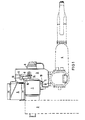
Figur 1 einen Querschnitt durch die Portalanordnung undFiguren 2 und 3 vergrößerte Ausschnitte von Rund- und Flachführung des Laufwagens.
- 1 shows a cross section through the portal arrangement and
- Figures 2 and 3 enlarged sections of the round and flat guide of the carriage.
Wie ersichtlich, besteht der Portalträger 1 aus einem quadratischen Hohlprofil. Der Träger läuft senkrecht zur Zeichenebene. An der Unterseite ist eine sich in Trägerlängsrichtung erstreckende Trägerleiste 15 aufgeschweißt, auf der eine Flachführung in Form eines Flachstahlbandes 11 aus Stahl angeordnet ist.As can be seen, the
An der Seite des Trägers 1 ist eine sich ebenfalls in Längsrichtung erstreckende Trägerleiste 16 vorgesehen, auf der in Abstand Wellenunterstützungen 8 mit hohem Widerstandsmoment befestigt sind. Auf den Wellenunterstützungen ruht eine Präzisionsstahlwelle 9, die als Rundführung dient. Diese Welle 9 erstreckt sich ebenfalls in Portallängsrichtung.Provided on the side of the
Der Laufwagen 3, der den eigentlichen Roboter 4 trägt, ist auf der Stahlwelle 9 durch vorgespannte Kugelführungsbuchsen 10 hoher Steifigkeit und mit umlaufendem Kugelführungssystem geführt. Ferner ist der Laufwagen an der Unterseite über vier Kurvenrollen, von denen nur die zwei Rollen 12 and 13 gezeigt sind, an der Flachführung seitlich abgestützt. Die Rollen können über Exzenter anstellbar montiert sein.The
Durch die Flach- und Rundführung ist eine absolut spielfreie, mit geringen Reibungsvedusten behaftete Führung des Laufwagens 3 sichergestellt.The flat and round guideway ensures that the
Der Laufwagen 3 selbst besteht zum Beispiel aus einem Aluminiumgußteil hoher Steifigkeit und Präzision. Die erforderlichen Anflanschflächen für das Führungssystem und den Antrieb mit Roboter können ebenfalls in einer Aufspannung auf einer Werkzeugmaschine hergestellt sein.The
Zum Antrieb des Laufwagens 3 ist ein Motor 6 vorgesehen, der über ein Zahnriemengetriebe ein Ritzel 72 antreibt, welches in eine am Träger 1 befestigte Zahnstange 71 eingreift. Verwendet man schrägverzahnte Zahnstangen und ein axial geteiltes Zahnrad, dessen Teile gegeneinander verspannt sind, als Ritzel, so erhält man eine große Laufruhe der Anordnung ohne Spiel.To drive the
Die Energiezuführung zum Laufwagen 3 wird mit einer Energiezuführungskette vorgenommen, die auf dem Träger 1 in einer U-förmigen Wanne 5 untergebracht ist.The energy supply to the
Der Träger 1 selbst kann, wie gestrichelt angedeutet, seitlich an Stützen 2 aufgehängt sein.The
Wie ersichtlich, ist der Aufbau des Führungs-und Antriebssystems in Träger-Längsrichtung so ausgeführt, daß beliebig viele Einzelträger mit entsprechender Abstützung aneinandergesetzt werden können, so daß die Verfahrlänge des Portalroboters beliebig erweitert werden kann.As can be seen, the structure of the guide and drive system in the longitudinal direction of the carrier is designed such that any number of individual carriers can be placed next to one another with appropriate support, so that the travel length of the portal robot can be extended as desired.
Die Rundführung des nachfolgenden Trägers wird in der Rundführung des vorhergehenden Trägers zentriert. Die Flachführungen stoßen stumpf ohne Stoßübergang aneinander. Die Zahnstange ist auf den nachfolgenden Träger übergreifend montiert.The rounding of the next carrier is in the rounding of the previous one Carrier centered. The flat guides butt against each other without a transition. The rack is mounted on the following carrier.
Claims (5)
Applications Claiming Priority (2)
| Application Number | Priority Date | Filing Date | Title |
|---|---|---|---|
| DE3532588 | 1985-09-12 | ||
| DE3532588 | 1985-09-12 |
Publications (2)
| Publication Number | Publication Date |
|---|---|
| EP0218878A1 EP0218878A1 (en) | 1987-04-22 |
| EP0218878B1 true EP0218878B1 (en) | 1989-12-13 |
Family
ID=6280802
Family Applications (1)
| Application Number | Title | Priority Date | Filing Date |
|---|---|---|---|
| EP86112078A Expired EP0218878B1 (en) | 1985-09-12 | 1986-09-01 | Gantry-type industrial robot |
Country Status (4)
| Country | Link |
|---|---|
| US (1) | US4802377A (en) |
| EP (1) | EP0218878B1 (en) |
| JP (1) | JPS6263071A (en) |
| DE (1) | DE3667421D1 (en) |
Families Citing this family (21)
| Publication number | Priority date | Publication date | Assignee | Title |
|---|---|---|---|---|
| AT389266B (en) * | 1983-06-28 | 1989-11-10 | Sticht Walter | Apparatus for manipulating components |
| DE3818922A1 (en) * | 1988-06-02 | 1989-12-07 | Mannesmann Ag | SUPPORT OF A CARRIER |
| EP0347705B1 (en) * | 1988-06-23 | 1993-01-07 | Siemens Aktiengesellschaft | Drive device for a portal traveller |
| DE19744488B4 (en) * | 1997-10-08 | 2006-10-26 | BSH Bosch und Siemens Hausgeräte GmbH | Robot for operating household appliances |
| CN100450728C (en) * | 2003-07-18 | 2009-01-14 | 美国发那科机器人有限公司 | Loading and unloading large and heavy workpieces by using portal frame remote control machine with two mechanical arms |
| US7662339B2 (en) * | 2004-10-22 | 2010-02-16 | Beckman Coulter, Inc. | Apparatus having improved gantry assembly suitable for use in a laboratory environment |
| US20060175291A1 (en) * | 2005-02-10 | 2006-08-10 | Hunt John A | Control of process gases in specimen surface treatment system |
| US20060226139A1 (en) * | 2005-04-06 | 2006-10-12 | Craig Jennings | Wok-piece positioner |
| US8831776B2 (en) | 2009-08-27 | 2014-09-09 | Sakura Finetek U.S.A., Inc. | Integrated tissue processing and embedding systems, and methods thereof |
| US8210418B1 (en) | 2011-06-09 | 2012-07-03 | Landoll Corporation | Multi-station, gantry-based automated welding system |
| US8434657B2 (en) | 2011-06-09 | 2013-05-07 | Landoll Corporation | Gantry-based welding system and method |
| CN102975193B (en) * | 2012-12-06 | 2014-08-27 | 爱马特(江苏)自动化有限公司 | Mechanical hand device capable of realizing horizontal conveyance along running beam for workpiece conveyance |
| US9650215B2 (en) | 2013-05-17 | 2017-05-16 | Intelligrated Headquarters Llc | Robotic carton unloader |
| US9487361B2 (en) | 2013-05-17 | 2016-11-08 | Intelligrated Headquarters Llc | Robotic carton unloader |
| WO2014186781A1 (en) | 2013-05-17 | 2014-11-20 | Intelligrated Headquarters, Llc | Robotic carton unloader |
| US10336562B2 (en) | 2013-05-17 | 2019-07-02 | Intelligrated Headquarters, Llc | Robotic carton unloader |
| WO2015017444A1 (en) | 2013-07-30 | 2015-02-05 | Intelligrated Headquarters Llc | Robotic carton unloader |
| BR112016004033A2 (en) | 2013-08-28 | 2017-12-12 | Intelligrated Headquarters Llc | robotic box dumper to unload a stack of boxes propped on a floor |
| CN103552063A (en) * | 2013-09-29 | 2014-02-05 | 爱马特(江苏)自动化有限公司 | Manipulator device with lifting rotary arms for transferring workpieces |
| US9623569B2 (en) | 2014-03-31 | 2017-04-18 | Intelligrated Headquarters, Llc | Autonomous truck loader and unloader |
| US10597235B2 (en) | 2016-10-20 | 2020-03-24 | Intelligrated Headquarters, Llc | Carton unloader tool for jam recovery |
Family Cites Families (15)
| Publication number | Priority date | Publication date | Assignee | Title |
|---|---|---|---|---|
| US2679940A (en) * | 1951-06-28 | 1954-06-01 | Atomic Energy Commission | Electrical manipulator |
| CH335237A (en) * | 1955-03-23 | 1958-12-31 | Goeckel Gmbh Maschf G | Guide for moving parts of machines with guide surfaces |
| NL267906A (en) * | 1960-08-19 | |||
| FR1352964A (en) * | 1963-01-09 | 1964-02-21 | Punching bench | |
| US3319802A (en) * | 1964-10-22 | 1967-05-16 | Ishikawajima Harima Heavy Ind | Single crane girder |
| US3359819A (en) * | 1966-04-25 | 1967-12-26 | Leo J Veillette | Bidirectional step torque filter with zero backlash characteristic |
| JPS522910A (en) * | 1975-06-24 | 1977-01-11 | Senyo Kiko Kk | Mono rail car |
| US4054330A (en) * | 1975-08-21 | 1977-10-18 | Hewlett-Packard Company | Suspension system for use with high speed printers |
| DE2623340C2 (en) * | 1976-05-25 | 1985-05-02 | Gewerkschaft Eisenhütte Westfalia, 4670 Lünen | Rack and pinion feed drive for a cutting machine |
| SU743862A1 (en) * | 1977-02-08 | 1980-06-30 | Московский Машиностроительный Завод "Салют" | Industrial robot |
| US4128278A (en) * | 1977-08-30 | 1978-12-05 | Brown & Sharpe Manufacturing Company | Linear motion ball bearing with dynamic stiffness |
| US4213732A (en) * | 1978-04-13 | 1980-07-22 | Westinghouse Electric Corp. | Apparatus for remotely repairing tubes in a steam generator |
| NL7808872A (en) * | 1978-08-29 | 1980-03-04 | Philips Nv | CONSTRUCTION SYSTEM FOR THE MANUFACTURE OF A TWO-LINE MOVABLE CONSTRUCTION PART. |
| IT1144707B (en) * | 1981-05-15 | 1986-10-29 | Dea Spa | OPERATING ARM UNIT CONTROLLED BY A COMPUTER SYSTEM |
| US4597707A (en) * | 1984-08-17 | 1986-07-01 | General Machine Design, Inc. | Automatic operating palletizer |
-
1986
- 1986-07-16 US US06/886,536 patent/US4802377A/en not_active Expired - Fee Related
- 1986-09-01 DE DE8686112078T patent/DE3667421D1/en not_active Expired - Lifetime
- 1986-09-01 EP EP86112078A patent/EP0218878B1/en not_active Expired
- 1986-09-04 JP JP61208821A patent/JPS6263071A/en active Pending
Also Published As
| Publication number | Publication date |
|---|---|
| EP0218878A1 (en) | 1987-04-22 |
| JPS6263071A (en) | 1987-03-19 |
| DE3667421D1 (en) | 1990-01-18 |
| US4802377A (en) | 1989-02-07 |
Similar Documents
| Publication | Publication Date | Title |
|---|---|---|
| EP0218878B1 (en) | Gantry-type industrial robot | |
| EP0252871B1 (en) | Industrial robot | |
| DE60209039T2 (en) | POSITIONING MACHINE WITH FLEXIBLE RAIL | |
| DE4224032C2 (en) | Drive system | |
| DE19654712A1 (en) | Machine with movable bridge with mutually movable supports | |
| DE3500742A1 (en) | ASSEMBLY FOR ASSEMBLY AND IN PARTICULAR STAPLING OF VEHICLE BODIES | |
| DE202017003923U1 (en) | Machining center for metal profiles | |
| EP1321225A2 (en) | Machining installation with at least one conveying system and a plurality of work stations | |
| EP0745453B1 (en) | Loaders and unloaders | |
| DE7710097U1 (en) | SIDE WALL OF A CARRIAGE | |
| DD240351A1 (en) | INDUSTRIAL ROBOT FOR THE HANDLING OF WORKPIECES AND TOOLS | |
| DE102004026151A1 (en) | Machining arrangement with multiple laser heads for cutting / welding and vibration control | |
| DE3704952C2 (en) | ||
| DE3603917C2 (en) | Positioning unit for the gripping head of a palletizer or the like. Positioning device | |
| DE102018102589A1 (en) | A drive arrangement for moving a workpiece as well as a machine arrangement provided with such a drive arrangement for machining a workpiece | |
| EP3064417B1 (en) | Transport device for moving work pieces for car bodywork construction in the motor vehicle industry | |
| EP0345536A2 (en) | Linear guide | |
| DE4111885C2 (en) | Handling device which is formed from module assemblies | |
| DE10151631B4 (en) | Movement and / or positioning device | |
| DE3400017C2 (en) | ||
| DE4113295A1 (en) | Motor vehicle body work prodn. - involves frame structure, assembly line running through frame, positioning tool drum rotating on carriage | |
| EP0779126B1 (en) | Machine tool with several drive units | |
| EP0607913B1 (en) | Device for feeding workpieces in an automatic wood-working machine tool | |
| DE8526088U1 (en) | Gantry device for an industrial robot | |
| DE8807313U1 (en) | Linear drive for handling tasks with two slides |
Legal Events
| Date | Code | Title | Description |
|---|---|---|---|
| PUAI | Public reference made under article 153(3) epc to a published international application that has entered the european phase |
Free format text: ORIGINAL CODE: 0009012 |
|
| AK | Designated contracting states |
Kind code of ref document: A1 Designated state(s): DE FR IT SE |
|
| 17P | Request for examination filed |
Effective date: 19870522 |
|
| 17Q | First examination report despatched |
Effective date: 19880608 |
|
| RAP1 | Party data changed (applicant data changed or rights of an application transferred) |
Owner name: SIEMENS AKTIENGESELLSCHAFT BERLIN UND MUENCHEN |
|
| GRAA | (expected) grant |
Free format text: ORIGINAL CODE: 0009210 |
|
| AK | Designated contracting states |
Kind code of ref document: B1 Designated state(s): DE FR IT SE |
|
| REF | Corresponds to: |
Ref document number: 3667421 Country of ref document: DE Date of ref document: 19900118 |
|
| ET | Fr: translation filed | ||
| ITF | It: translation for a ep patent filed | ||
| PGFP | Annual fee paid to national office [announced via postgrant information from national office to epo] |
Ref country code: SE Payment date: 19900913 Year of fee payment: 5 |
|
| PLBI | Opposition filed |
Free format text: ORIGINAL CODE: 0009260 |
|
| PLBI | Opposition filed |
Free format text: ORIGINAL CODE: 0009260 |
|
| PGFP | Annual fee paid to national office [announced via postgrant information from national office to epo] |
Ref country code: FR Payment date: 19900925 Year of fee payment: 5 |
|
| ITTA | It: last paid annual fee | ||
| 26 | Opposition filed |
Opponent name: IGM-ROBOTERSYSTEME AKTIENGESELLSCHAFT Effective date: 19900905 |
|
| 26 | Opposition filed |
Opponent name: ASEA BROWN BOVERI AB Effective date: 19900907 Opponent name: IGM-ROBOTERSYSTEME AKTIENGESELLSCHAFT Effective date: 19900905 |
|
| PGFP | Annual fee paid to national office [announced via postgrant information from national office to epo] |
Ref country code: DE Payment date: 19901126 Year of fee payment: 5 |
|
| RDAG | Patent revoked |
Free format text: ORIGINAL CODE: 0009271 |
|
| STAA | Information on the status of an ep patent application or granted ep patent |
Free format text: STATUS: PATENT REVOKED |
|
| 27W | Patent revoked |
Effective date: 19910413 |
|
| EUG | Se: european patent has lapsed |
Ref document number: 86112078.0 Effective date: 19910828 |