EP0218751B1 - Stereoscopic remote viewing system - Google Patents
Stereoscopic remote viewing system Download PDFInfo
- Publication number
- EP0218751B1 EP0218751B1 EP85113213A EP85113213A EP0218751B1 EP 0218751 B1 EP0218751 B1 EP 0218751B1 EP 85113213 A EP85113213 A EP 85113213A EP 85113213 A EP85113213 A EP 85113213A EP 0218751 B1 EP0218751 B1 EP 0218751B1
- Authority
- EP
- European Patent Office
- Prior art keywords
- platform
- track
- viewing system
- video
- stereoscopic
- Prior art date
- Legal status (The legal status is an assumption and is not a legal conclusion. Google has not performed a legal analysis and makes no representation as to the accuracy of the status listed.)
- Expired - Lifetime
Links
Images


Classifications
-
- A—HUMAN NECESSITIES
- A61—MEDICAL OR VETERINARY SCIENCE; HYGIENE
- A61B—DIAGNOSIS; SURGERY; IDENTIFICATION
- A61B1/00—Instruments for performing medical examinations of the interior of cavities or tubes of the body by visual or photographical inspection, e.g. endoscopes; Illuminating arrangements therefor
- A61B1/00163—Optical arrangements
- A61B1/00193—Optical arrangements adapted for stereoscopic vision
-
- G—PHYSICS
- G02—OPTICS
- G02B—OPTICAL ELEMENTS, SYSTEMS OR APPARATUS
- G02B27/00—Optical systems or apparatus not provided for by any of the groups G02B1/00 - G02B26/00, G02B30/00
- G02B27/01—Head-up displays
- G02B27/0101—Head-up displays characterised by optical features
-
- G—PHYSICS
- G02—OPTICS
- G02B—OPTICAL ELEMENTS, SYSTEMS OR APPARATUS
- G02B30/00—Optical systems or apparatus for producing three-dimensional [3D] effects, e.g. stereoscopic images
- G02B30/20—Optical systems or apparatus for producing three-dimensional [3D] effects, e.g. stereoscopic images by providing first and second parallax images to an observer's left and right eyes
- G02B30/34—Stereoscopes providing a stereoscopic pair of separated images corresponding to parallactically displaced views of the same object, e.g. three-dimensional [3D] slide viewers
- G02B30/35—Stereoscopes providing a stereoscopic pair of separated images corresponding to parallactically displaced views of the same object, e.g. three-dimensional [3D] slide viewers using reflective optical elements in the optical path between the images and the observer
-
- H—ELECTRICITY
- H04—ELECTRIC COMMUNICATION TECHNIQUE
- H04N—PICTORIAL COMMUNICATION, e.g. TELEVISION
- H04N13/00—Stereoscopic video systems; Multi-view video systems; Details thereof
- H04N13/10—Processing, recording or transmission of stereoscopic or multi-view image signals
- H04N13/106—Processing image signals
- H04N13/158—Switching image signals
-
- H—ELECTRICITY
- H04—ELECTRIC COMMUNICATION TECHNIQUE
- H04N—PICTORIAL COMMUNICATION, e.g. TELEVISION
- H04N13/00—Stereoscopic video systems; Multi-view video systems; Details thereof
- H04N13/10—Processing, recording or transmission of stereoscopic or multi-view image signals
- H04N13/194—Transmission of image signals
-
- H—ELECTRICITY
- H04—ELECTRIC COMMUNICATION TECHNIQUE
- H04N—PICTORIAL COMMUNICATION, e.g. TELEVISION
- H04N13/00—Stereoscopic video systems; Multi-view video systems; Details thereof
- H04N13/20—Image signal generators
- H04N13/204—Image signal generators using stereoscopic image cameras
- H04N13/239—Image signal generators using stereoscopic image cameras using two two-dimensional [2D] image sensors having a relative position equal to or related to the interocular distance
-
- H—ELECTRICITY
- H04—ELECTRIC COMMUNICATION TECHNIQUE
- H04N—PICTORIAL COMMUNICATION, e.g. TELEVISION
- H04N13/00—Stereoscopic video systems; Multi-view video systems; Details thereof
- H04N13/20—Image signal generators
- H04N13/275—Image signal generators from three-dimensional [3D] object models, e.g. computer-generated stereoscopic image signals
-
- H—ELECTRICITY
- H04—ELECTRIC COMMUNICATION TECHNIQUE
- H04N—PICTORIAL COMMUNICATION, e.g. TELEVISION
- H04N13/00—Stereoscopic video systems; Multi-view video systems; Details thereof
- H04N13/20—Image signal generators
- H04N13/296—Synchronisation thereof; Control thereof
-
- H—ELECTRICITY
- H04—ELECTRIC COMMUNICATION TECHNIQUE
- H04N—PICTORIAL COMMUNICATION, e.g. TELEVISION
- H04N13/00—Stereoscopic video systems; Multi-view video systems; Details thereof
- H04N13/30—Image reproducers
- H04N13/332—Displays for viewing with the aid of special glasses or head-mounted displays [HMD]
- H04N13/344—Displays for viewing with the aid of special glasses or head-mounted displays [HMD] with head-mounted left-right displays
-
- H—ELECTRICITY
- H04—ELECTRIC COMMUNICATION TECHNIQUE
- H04N—PICTORIAL COMMUNICATION, e.g. TELEVISION
- H04N13/00—Stereoscopic video systems; Multi-view video systems; Details thereof
- H04N13/10—Processing, recording or transmission of stereoscopic or multi-view image signals
- H04N13/189—Recording image signals; Reproducing recorded image signals
-
- H—ELECTRICITY
- H04—ELECTRIC COMMUNICATION TECHNIQUE
- H04N—PICTORIAL COMMUNICATION, e.g. TELEVISION
- H04N13/00—Stereoscopic video systems; Multi-view video systems; Details thereof
- H04N13/20—Image signal generators
- H04N13/204—Image signal generators using stereoscopic image cameras
- H04N13/207—Image signal generators using stereoscopic image cameras using a single two-dimensional [2D] image sensor
- H04N13/221—Image signal generators using stereoscopic image cameras using a single two-dimensional [2D] image sensor using the relative movement between cameras and objects
-
- H—ELECTRICITY
- H04—ELECTRIC COMMUNICATION TECHNIQUE
- H04N—PICTORIAL COMMUNICATION, e.g. TELEVISION
- H04N13/00—Stereoscopic video systems; Multi-view video systems; Details thereof
- H04N13/20—Image signal generators
- H04N13/286—Image signal generators having separate monoscopic and stereoscopic modes
-
- H—ELECTRICITY
- H04—ELECTRIC COMMUNICATION TECHNIQUE
- H04N—PICTORIAL COMMUNICATION, e.g. TELEVISION
- H04N13/00—Stereoscopic video systems; Multi-view video systems; Details thereof
- H04N13/30—Image reproducers
- H04N13/356—Image reproducers having separate monoscopic and stereoscopic modes
-
- H—ELECTRICITY
- H04—ELECTRIC COMMUNICATION TECHNIQUE
- H04N—PICTORIAL COMMUNICATION, e.g. TELEVISION
- H04N13/00—Stereoscopic video systems; Multi-view video systems; Details thereof
- H04N13/30—Image reproducers
- H04N13/398—Synchronisation thereof; Control thereof
Definitions
- the present invention relates to remote video systems and, more particularly, to a stereoscopic video system with a head worn display for use as in the control of an industrial robot.
- Certain manufacturing operations lend themselves to performance by manually controlled industrial robots because of the hazardous nature of such operations.
- the hazards arise from the materials involved such as explosive, corrosive, pathogenic, cryogenic, radioactive or the like materials or from the necessity of performing such operations in atmospheres which are poisonous or non- life supporting to humans such as welding in inert gases or operations which require a vacuum.
- Other situations which benefit from manually controlled robotics include operations which are necessarily carried out by remote control such as some deep sea operations and outer space operations. While some such operations can be performed by automatically controlled robots with feedback loops for selfcor- rection, others require direct human control.
- the primary human feedback senses for manual activities are usually vision and touch or feel. considerable effort has been expended in the development of remote controls which have a useful feel such that a given amount of manual movement of a control results in an expected result. A portion of the success of such a control involves learning to use the control by the operator.
- image (video camera) tubes and picture tubes, or cathode ray tubes (CRT's) have been miniaturized to the extent that a pair of image tubes can be positioned to approximate the perspective of the human eyes; and a pair of CRT's can be positioned and the images projected preferably indirectly, to the eyes of a human such that a good approximation of natural stereoscopic vision can be achieved.
- Non-CRT visual display devices such as liquid crystal, light emitting diode, and fluorescent matrix displays are currently being applied to reduce the size of video displays even further.
- a stereoscopic remote viewing system including first and second image sensors spaced apart to provide a left video signal and a right video signal, said video signals representing scenes as sensed by said image sensors, a platform supporting said sensors for convergence of lines of sight of said sensors substantially at a subject to be viewed, a movable support for moving said platform in three dimensions selectively to aim said sensors, and a motor for moving said platform support and a control associated with said motor, characterized by a head unit adapted for wearing on the head of a viewer, a first video display device directly linked with said first image sensor, a second video display device directly linked with said second image sensor respectively to receive said left and right video signals and display images which are reproductions of scenes sensed by said image sensors, said first and second video display devices being mounted on said head unit and cooperating with said first and second image sensors to provide a natural vision stereoscopic image to the viewer.
- the present invention provides apparatus for stereoscopically viewing a remote subject.
- the apparatus includes a pair of video cameras mounted on a platform which is capable of movement in three dimensions.
- the cameras include motors for focus and zoom control and convergence motors such that the lines of sight of the cameras coincide at the focal point of the cameras.
- the camera platform is mounted on a semicircular track and is movable therealong for azimuth aiming of the cameras.
- the track is rotatable about a diametric axis for elevation of the cameras.
- the cameras are coupled to a head worn video display unit including means such as a helmet with a pair of video display devices such as miniature cathode ray tubes or picture tubes and optical and mirror or prismatic elemtens to project the displayed images into focus in the eyes of a viewer wearing the video display.
- the helmet also includes circuitry for generating sweep signals for the CRT's and circuits for processing the video signals from the cameras.
- a computer system is connected to the stereoscopic display through a video source selector for the display of reference texts and graphics related to the operation to be performed by a robotic device associated with the viewing system.
- the computer is controlled to feed the same image to the right and left video channels for a binocular monoscopic view of such information.
- the principal objects of the present invention are: to provide an improved apparatus for remotely viewing manually controlled operations; to provide such an apparatus which facilitates the remote operation of a robotic arm and hand device; to provide such an apparatus which provides a three dimensional or in view of a remote operation; to provide such an apparatus including a pair of movably mounted video cameras and a corresponding pair of video displays adapted as a head worn stereoscopic unit for placement on the head of a viewer to project a pair of images from the cameras into the eyes of the viewer; to provide such an apparatus wherein the cameras are mounted on a bracket or platform which is positioned on a semicircular track for movement along the track for azimuth aiming of the cameras, the semicircular track being rotatable about a horizontal diametric axis for elevation aiming of the cameras; to provide such an apparatus including controls for focusing the cameras and zooming of the cameras to change perspective and viewed size of the subject; to provide such an apparatus including means for maintaining the focus and line of sight convergence of the cameras during zooming; to provide such an apparatus including
- the reference numeral 1 generally designates a stereoscopic remote viewing system according to the present invention.
- the system 1 generally includes a pair of video cameras 2 and 3 mounted on a three dimensionally movable camera aiming support 4 and a pair of video display devices 5 and 6 (Figs. 5-7) mounted in a video display unit 7 which is adapted to be worn on the head of a viewing individual.
- the display unit 7 includes video circuitry 8 (Fig. 8) to adapt the display devices 5 and 6 as video monitors for viewing the images sensed by the cameras 2 and 3.
- the cameras 2 and 3 are positioned to capture a stereoscopic view of a scene; and similarly the display devices 5 and 6 are positioned to provide a stereoscopic display of the reproduced images for the viewer.
- a system control console 9 allows the viewer to control the position and the optical features of the camera 2 and 3.
- a computer system 10 is selectively connected to the video display unit 7 and is employed to store and retrieve digitally encoded texts and graphics for display on the video display unit 7.
- the system 1 is particularly adapted for remotely viewing operations such as the operations of a remotely controlled robotic device 110.
- the cameras 2 and 3 are mounted in spaced relation on a camera bracket or platform 14 which is, in turn, mounted for movement along the camera aiming support 4.
- the support 4 is a semicircular guide track which is pivotally connected at extremities of the track 4 to track supports 15 for rotation of the track 4 about a horizontal diametric axis 16 of the track 4.
- the illustrated track 4 has square tubular cross section.
- the extremities 17 of the track 4 extend past the pivot joints 18 which connect the track 4 to the supports 15.
- the extremities 17 preferably have counterweights 19 thereon to counterbalance the track structure on the pivot joints 18.
- An elevation motor 20 is mounted on one of the track supports 15 and operatively engages the track 4 to pivot same for elevation aiming of the cameras 2 and 3.
- a helical or worm gear in a housing 21 is positioned on a rotary shaft of the motor 20 and engages a pinion gear in a housing 22 and fixed on a pivot shaft 23 of the track 4.
- the degree of angular movement of the track 4 which is allowable or desired is determined by the dimensions of the track 4 in comparison to the height of the supports 15 and the degree of coverage of the operation required.
- the track 4 is able to cover at least a hemisphere.
- the camera platform 14 may be any structure which supports the cameras 2 and 3 for movement along the track 4.
- the platform 14 illustrated in Fig. 4 includes an inner bracket 26 and an outer bracket 27 joined by sets of opposed side rollers 28 which contact side walls 29 of the track 4.
- An inner set of rollers 30 engages an inside wall 31 of the track 4.
- the outer wall 32 has an elongated rack gear 33 positioned on the outer surface thereof.
- the gear 33 cooperates with a helical or worm gear 34 which is affixed to the rotary shaft of an azimuth motor 35 which is mounted on the outer bracket 27. Rotation of the worm gear 34 causes the platform 14 to move along the track 4 for azimuth aiming of the cameras 2 and 3.
- the rollers 28 and 30 are preferably resiliently urged against the respective walls of the track 4 such that the platform 14 is securely held on the track 4.
- the left hand camera 2 includes a left image sensor 38 and left camera optics 39 while the right camera 3 includes a right image sensor 40 and right camera optics 41.
- the image sensors 38 and 40 may be any type of conventional video image sensors including solid state image sensors.
- the optics 39 and 41 are mounted in the cameras 2 and 3 for movement along respective lines of sight or optical axes 42 or 43 to focus an image on the associated image sensor and to change the optical perspective of the image transmitted to the associated image sensor.
- the left video camera 2 includes a left focus motor 44 and a left zoom motor 45 while the right video camera 3 includes a right focus motor 46 and a right zoom motor 47.
- the cameras 2 and 3 include focus convergence motors 48 and 49 respectively.
- the cameras 2 and 3 are mounted for rotation substantially in the plane of the platform track 4 and have the motors 48 and 49 connecting the associated cameras to the inner bracket 26 of the camera platform 14.
- the focus convergence motors 48 and 49 are activated to maintain the coincidence of the focal points of the cameras 2 and 3 as the focal points of the cameras are changed by operation of the focus motors 44 and 46.
- the left and right image sensors 38 and 40 are provided with common sync signals provided by a sync generator 52 such that the scans of the left and right image sensors 38 and 40 are synchronized.
- the cameras 2 and 3 include means for maintaining focused images as the optics 39 and 41 are zoomed. Mechanical arrangements for maintaining focus during zooming are known and may be employed in the system 1.
- the camera unit 54 includes a zoom autofocus controller 55 which is a dedicated control computer interconnected with the focus motors 44 and 46, the zoom motors 45 and 47, and the focus convergence motors 48 and 49. Autofocus controller arrangements for monoscopic lens systems are known.
- the autofocus controller 55 is adapted for maintaining the focus during zooming for the left and right cameras 2 and 3, and, further, controls the convergence of the focal points of the cameras 2 and 3.
- sensors would be required for determining the positions of the left and right optics 39 and 41 for the generation of autofocus control signals. Such sensing could include shaft encoders of various descriptions positioned on the shafts of the motors of the camera unit 54. The details of such position sensors are believed to be within the capabilities of one skilled in the digital control of electric motors.
- the viewing system control panel 9 includes an elevation control 58 connected to the platform elevation motor 20 and an azimuth control 59 connected to the platform azimuth motor 35.
- the manual focus control 60 is provided for fine adjustment of the focal positions of the left and right optics 39 and 41 in unison.
- a focal balance control 61 provides for differential adjustment of the focal positions of the optics 39 and 41 to compensate for the individual visual acuities of the user of the system 1.
- a zoom control 62 is operated to cause zooming of the left and right optics 39 and 41 in unison.
- the controls 60, 61, and 62 are operatively connected to the motors of the camera unit 54 through the zoom autofocus controller block 55.
- Figs. 5-7 illustrate details of the head worn video display unit 7.
- the unit 7 includes a cap or helmet 65 in which the components of the unit 7 are mounted.
- the illustrated video display devices 5 and 6 are CRT's and are mounted within the helmet 65 for indirect projection of the images therefrom into the eyes of the viewer 66 in order to decrease the possibility of projecting X-rays into the eyes of the viewer.
- the use of solid state matrix displays instead of the CRT's 5 and 6 is contemplated such that the system 1 is not to be limited to the use of CRT's as video display devices.
- the CRT's 5 and 6 are mounted for downward projection of the images thereof through projection optical elements 67 toward right angle reflecting elements 68 such as mirrors or prisms and from there through viewing lenses 69 to the eyes of the viewer 66.
- the viewing lenses 69 are provided to compensate for the short focal distance between the eyes of the viewer 66 and the display devices 5 and 6 such that the images can be focused at a greater effective distance.
- the viewing lenses 69 are preferably finely adjustable to accommodate the visual capabilities of the eyes of the viewer 66.
- the lateral positions of the right and left video display components are preferably adjustable to accommodate the spacing between the eyes of the viewer 66, although such adjustment means are not illustrated.
- the components of the video display unit 7 comprise a head worn stereoscopic video monitor unit. Therefore, the left and right video channels include respective left and right video monitor circuitry 72 and 73.
- the monitor circuits 72 and 73 include sweep generators for generating the rasters on the displays 5 and 6 and further include video signal demultiplexers for separating sync and luminance signals from composite signals if such composite signals are employed, and conventional video circuits for processing and displaying the images represented by the video signals. If color technology is employed in the system 1, it is foreseen that the color component signals may either be provided as right and left color composite signals or as separated red, green, and blue (RGB) sets of color signals.
- the left and right monitor circuits are conventional and are configured according to the requirements of the system.
- each of the circuits 72 and 73 be mounted within the helmet 65 such as within ear bosses 75 or in an enlargement such as at the rear of the helmet 65 (hot shown) to provide better balance of the helmet 65.
- each of the circuits 72 and 73 includes at least a brightness control 77 and a contrast control 78 for adjustment of the displayed images. If color is provided in the system 1, color level and tint or individual RGB color controls (not shown) would appropriately be provided.
- an on/off-power switch 79 is provided for activating and deactivating the components within the video display unit 7.
- the video signals from the cameras 2 and 3 are provided to the components within the helmet 65 as by a cable 80 which conveniently enters the video display unit 7 at the rear of the helmet 65.
- the helmet 65 preferably includes an adjustable harness for fitting the helmet to the head of the viewer 66.
- Means such as an elastic band 81 may be provided to retain the helmet in position on the head of the viewer.
- a forehead pad 82 is provided to maintain the position of the optical elements of the display unit 7 in relation to the eyes of the viewer.
- X-Ray shields 83 are preferably positioned to enclose the CRT's 5 and 6, particularly if color CRT's are employed.
- the video signals from the left and right video cameras 2 and 3 are provided to the video display unit 7 through a right and left video source switch 86.
- the video source switch 86 also has the video output from the computer system 10 connected thereto whereby the video display unit 7 may be driven either by the computer system 10 or the video cameras 2 and 3.
- the video source switch 86 may include conventional switch components or coaxial switch components which are properly sequenced to isolate one video source from another.
- the video source switch components are operated by solenoid means (not shown) under control of the computer system 10.
- the switch 86 may be further expanded to provide for selection of other video sources such as video tape recorders, video discs, or television tuners (not shown).
- the video source switch 86 could be configured to allow the routing of video signals from the cameras 2 and 3 to the video display unit 7 and, additionally, to video recording devices to record the images as viewed for later analysis or for digitization and storage within a computer system such as the computer system 10.
- the computer system 10 is, for the most part, a conventional general purpose digital computer.
- the illustrated computer system 10 includes a central processing unit or main computer board 88, a main computer memory 89, a keyboard 90, mass storage devices such as discs 91, and a communications interface 92 for communication between the computer system 10 and another computer.
- computers particularly microcomputers, only require a single video channel for displaying text or graphics on a video monitor associated therewith.
- the computer system 10 has left and right video channels interfaced thereto.
- the left and right hand video channels include respectively a left and a right video display generator 93 and 94.
- the video display generators 93 and 94 include associated video memories or video random access read/write memories (VRAM) 95 and 96. In general, the video display generators derive respective analog video signals from the digital information stored within the video memories 95 and 96. Further, the generators 93 and 94 control the flow of digital data from the computer 88 to the video memories 95 and 96.
- the video display generators 93 and 94 are essentially conventional and are preferably capable of high resolution displays.
- the generators 93 and 94 include respective address decoders for the proper routing of video information from the computer board 88 to the generators 93 and 94 over a video bus 98 which is interfaced to the computer board 88 through a video port.
- the right and left video display generators 93 and 94 are connected to a common clock line 99 of the video bus 98.
- the video source switch 86 receives a selection command from a video source selection port 100 which is interfaced to the computer board 88.
- the operator or viewer 66 selects the desired video source by operation of a key or keys on the keyboard 90.
- the computer system 10 includes software for operation of the video source switch 86 and for storing, retrieving, and routing digitized images from the mass storage device 91 to the video display unit 7.
- the digitized images provided by the computer system 10 may be either stereoscopic or monoscopic whereas text which is displayed on the unit 7 need only be monoscopic.
- the computer 88 feeds the same display data to the left and right display generators 93 and 94.
- different video data is routed to the left and right display generators 93 and 94.
- the computer system 10 may be programmed to display a menu upon the operation of a selected key on the keyboard 90 for the selection of functions related to the system 1 or may be programmed to respond to specific spelled-out commands.
- the viewing system 1 is particularly well adapted for remotely viewing an operation such as detailed manufacturing operations performed by a manually controlled robotic device.
- the robotic device 110 illustrated in Figs. 1 and 2 includes a robotic arm 103 having a tool 104 attached thereto.
- the robotic device 110 is controlled as by the manipulation of robot control levers 105 which may be associated with either the control console 9 or the keyboard 90.
- the robotic arm 103 is controlled to selectively position the tool 104 for operations on a workpiece 106 positioned on a workpiece support 107.
- the camera unit 54 may be placed anywhere along the platform guide track 4 and the track pivoted about its axis 16 to provide the best view to the operator 66.
- the stereoscopic images provided by the system 1 greatly facilitates the remote placement of the tool 104 in three dimensional space with respect to the workpiece 106.
- the computer system 10 provides for the display of texts such as instructions or procedures related to the operations performed by the robotic device 110 and viewed by the viewing system 1. Further, diagrammatic information and three dimensional graphic information can be recalled by the computer system 10 from the mass storage device 91 and displayed on the video display unit 7 for viewing by the operator 66. Such graphic information is intended to relate to the operations performed with the robotic device 110 and may include patterns for comparison with the workpiece being operated upon, views of a finished product, and the like.
Landscapes
- Engineering & Computer Science (AREA)
- Physics & Mathematics (AREA)
- Multimedia (AREA)
- Signal Processing (AREA)
- Optics & Photonics (AREA)
- General Physics & Mathematics (AREA)
- Health & Medical Sciences (AREA)
- Life Sciences & Earth Sciences (AREA)
- Surgery (AREA)
- Pathology (AREA)
- Nuclear Medicine, Radiotherapy & Molecular Imaging (AREA)
- Radiology & Medical Imaging (AREA)
- Biophysics (AREA)
- Biomedical Technology (AREA)
- Heart & Thoracic Surgery (AREA)
- Medical Informatics (AREA)
- Molecular Biology (AREA)
- Animal Behavior & Ethology (AREA)
- General Health & Medical Sciences (AREA)
- Public Health (AREA)
- Veterinary Medicine (AREA)
- Testing, Inspecting, Measuring Of Stereoscopic Televisions And Televisions (AREA)
Description
- The present invention relates to remote video systems and, more particularly, to a stereoscopic video system with a head worn display for use as in the control of an industrial robot.
- Certain manufacturing operations lend themselves to performance by manually controlled industrial robots because of the hazardous nature of such operations. The hazards arise from the materials involved such as explosive, corrosive, pathogenic, cryogenic, radioactive or the like materials or from the necessity of performing such operations in atmospheres which are poisonous or non- life supporting to humans such as welding in inert gases or operations which require a vacuum. Other situations which benefit from manually controlled robotics include operations which are necessarily carried out by remote control such as some deep sea operations and outer space operations. While some such operations can be performed by automatically controlled robots with feedback loops for selfcor- rection, others require direct human control.
- The primary human feedback senses for manual activities are usually vision and touch or feel. considerable effort has been expended in the development of remote controls which have a useful feel such that a given amount of manual movement of a control results in an expected result. A portion of the success of such a control involves learning to use the control by the operator.
- The development of "remote sight" has, to an extent, lagged the development of remote manipulation because of the complexities of human vision and the complexities of the systems for aiding human vision, namely, television. Human vision is stereoscopic; that is, the right and left eyes sense slightly different images because of the lateral separation therebetween. The brain interprets the difference in image to derive depth perception such that a three dimensional visual sense results. Through practice as an individual ages, eye-hand coordination can become quite accurate.
- Television has for the most part been a two dimensional medium, notwithstanding such techniques in color television as so-called "3D" effects wherein two of the component colors, such as red and green, are offset laterally and when viewed through a set of properly oriented red and green spectacle lenses gives an approximation of three dimensional vision. Such effects, while arguably adequate for applications as in motion pictures, do not convey an accurate enough sense of depth for such activities as the control of a robotic arm. In order to obtain a truer video image of the depth dimension, that is in the direction of the line of sight of a video camera, a second video camera which is laterally spaced or elevated from the first camera has been required. A viewer is then required to watch and coordinate the images on two separate viewing screens.
- The result is an improvement over two dimensional viewing, but does not provide the apparent simplicity and the convenience of natural vision.
- In more recent years, image (video camera) tubes and picture tubes, or cathode ray tubes (CRT's), have been miniaturized to the extent that a pair of image tubes can be positioned to approximate the perspective of the human eyes; and a pair of CRT's can be positioned and the images projected preferably indirectly, to the eyes of a human such that a good approximation of natural stereoscopic vision can be achieved. Non-CRT visual display devices such as liquid crystal, light emitting diode, and fluorescent matrix displays are currently being applied to reduce the size of video displays even further.
- The article appearing in volume 36 (No. 11/1982: pages 441-445) of F & KT - Fernseh- und Kino-Technik is concerned with manipulation and orientation of sensing cameras and general view of images produced thereby.
- According to the present invention there is provided a stereoscopic remote viewing system including first and second image sensors spaced apart to provide a left video signal and a right video signal, said video signals representing scenes as sensed by said image sensors, a platform supporting said sensors for convergence of lines of sight of said sensors substantially at a subject to be viewed, a movable support for moving said platform in three dimensions selectively to aim said sensors, and a motor for moving said platform support and a control associated with said motor, characterized by a head unit adapted for wearing on the head of a viewer, a first video display device directly linked with said first image sensor, a second video display device directly linked with said second image sensor respectively to receive said left and right video signals and display images which are reproductions of scenes sensed by said image sensors, said first and second video display devices being mounted on said head unit and cooperating with said first and second image sensors to provide a natural vision stereoscopic image to the viewer.
- The present invention provides apparatus for stereoscopically viewing a remote subject. The apparatus includes a pair of video cameras mounted on a platform which is capable of movement in three dimensions. The cameras include motors for focus and zoom control and convergence motors such that the lines of sight of the cameras coincide at the focal point of the cameras. The camera platform is mounted on a semicircular track and is movable therealong for azimuth aiming of the cameras. The track is rotatable about a diametric axis for elevation of the cameras.
- The cameras are coupled to a head worn video display unit including means such as a helmet with a pair of video display devices such as miniature cathode ray tubes or picture tubes and optical and mirror or prismatic elemtens to project the displayed images into focus in the eyes of a viewer wearing the video display. The helmet also includes circuitry for generating sweep signals for the CRT's and circuits for processing the video signals from the cameras.
- A computer system is connected to the stereoscopic display through a video source selector for the display of reference texts and graphics related to the operation to be performed by a robotic device associated with the viewing system. For displaying texts and graphics which do not require a stereoscopic display, the computer is controlled to feed the same image to the right and left video channels for a binocular monoscopic view of such information.
- The principal objects of the present invention are: to provide an improved apparatus for remotely viewing manually controlled operations; to provide such an apparatus which facilitates the remote operation of a robotic arm and hand device; to provide such an apparatus which provides a three dimensional or in view of a remote operation; to provide such an apparatus including a pair of movably mounted video cameras and a corresponding pair of video displays adapted as a head worn stereoscopic unit for placement on the head of a viewer to project a pair of images from the cameras into the eyes of the viewer; to provide such an apparatus wherein the cameras are mounted on a bracket or platform which is positioned on a semicircular track for movement along the track for azimuth aiming of the cameras, the semicircular track being rotatable about a horizontal diametric axis for elevation aiming of the cameras; to provide such an apparatus including controls for focusing the cameras and zooming of the cameras to change perspective and viewed size of the subject; to provide such an apparatus including means for maintaining the focus and line of sight convergence of the cameras during zooming; to provide such an apparatus including a computer selectively connected to the stereoscopic display unit for the display of texts and graphic information related to the operation performed during use of the viewing system; and to provide such a stereoscopic viewing system which is economical to manufacture, convenient in operation, and which is particularly well adapted for its intended purpose.
- Other objects and advantages of this invention will become apparent from the following description taken in conjunction with the accompanying
drawings 5 wherein are set forth, by way of illustration and example, certain embodiments of this invention. - The drawings constitute a part of this specification and include exemplary embodiments of the present invention and illustrate various objects and features thereof.
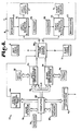
- Fig. 1 is a diagrammatic plan view of a stereoscopic remote viewing system according to the present invention, shown in association with a manually controlled robotic device.
- Fig. 2 is a side elevational view of a movable camera platform support of the system.
- Fig. 3 is an enlarged fragmentary plan view of the video camera platform.
- Fig. 4 is a further enlarged sectional view taken on line 4-4 of Fig. 3 and illustrates details of the video camera unit.
- Fig. 5 is a side elevational view of a stereoscopic display unit of the system with portions broken away to illustrate the optical elements which project a pair of images into the eyes of the viewer.
- Fig. 6 is a front elevational view of the display unit of the system.
- Fig. 7 is a top plan view of the display unit with portions broken away to illustrate further details of the projection optics.
- Fig. 8 is a block diagram illustrating the functional relationships of a computer system for storing and recalling texts and graphics related to the operation performed and viewed through the viewing system, a pair of video cameras, and the display unit.
- Fig. 9 is a block diagram illustrating controls for operation of the camera unit of the viewing system.
- As required, detailed embodiments of the present invention are disclosed herein; however, it is to be understood that the disclosed embodiments are merely exemplary of the invention which may be embodied in various forms. Therefore, specific structural and functional details disclosed herein are not to be interpreted as limiting, but merely as a basis for the claims and as a representative basis for teaching one skilled in the art to variously employ the present invention in virtually any appropriately detailed structure.
- The reference numeral 1 generally designates a stereoscopic remote viewing system according to the present invention. The system 1 generally includes a pair of
video cameras camera aiming support 4 and a pair ofvideo display devices 5 and 6 (Figs. 5-7) mounted in avideo display unit 7 which is adapted to be worn on the head of a viewing individual. Thedisplay unit 7 includes video circuitry 8 (Fig. 8) to adapt thedisplay devices cameras cameras display devices camera computer system 10 is selectively connected to thevideo display unit 7 and is employed to store and retrieve digitally encoded texts and graphics for display on thevideo display unit 7. The system 1 is particularly adapted for remotely viewing operations such as the operations of a remotely controlledrobotic device 110. - Referring to Fig. 3, the
cameras platform 14 which is, in turn, mounted for movement along thecamera aiming support 4. Thesupport 4 is a semicircular guide track which is pivotally connected at extremities of thetrack 4 to track supports 15 for rotation of thetrack 4 about a horizontaldiametric axis 16 of thetrack 4. The illustratedtrack 4 has square tubular cross section. Theextremities 17 of thetrack 4 extend past thepivot joints 18 which connect thetrack 4 to thesupports 15. Theextremities 17 preferably havecounterweights 19 thereon to counterbalance the track structure on thepivot joints 18. Anelevation motor 20 is mounted on one of the track supports 15 and operatively engages thetrack 4 to pivot same for elevation aiming of thecameras motor 20 and engages a pinion gear in ahousing 22 and fixed on apivot shaft 23 of thetrack 4. The degree of angular movement of thetrack 4 which is allowable or desired is determined by the dimensions of thetrack 4 in comparison to the height of thesupports 15 and the degree of coverage of the operation required. Preferably, thetrack 4 is able to cover at least a hemisphere. - The
camera platform 14 may be any structure which supports thecameras track 4. Theplatform 14 illustrated in Fig. 4 includes aninner bracket 26 and anouter bracket 27 joined by sets ofopposed side rollers 28 whichcontact side walls 29 of thetrack 4. An inner set ofrollers 30 engages aninside wall 31 of thetrack 4. Theouter wall 32 has anelongated rack gear 33 positioned on the outer surface thereof. Thegear 33 cooperates with a helical orworm gear 34 which is affixed to the rotary shaft of anazimuth motor 35 which is mounted on theouter bracket 27. Rotation of theworm gear 34 causes theplatform 14 to move along thetrack 4 for azimuth aiming of thecameras rollers track 4 such that theplatform 14 is securely held on thetrack 4. - Referring to Figs. 3, 4, and 9, the
left hand camera 2 includes aleft image sensor 38 and leftcamera optics 39 while theright camera 3 includes aright image sensor 40 andright camera optics 41. Theimage sensors optics cameras optical axes left video camera 2 includes aleft focus motor 44 and aleft zoom motor 45 while theright video camera 3 includes aright focus motor 46 and aright zoom motor 47. In order for a useful stereoscopic image to be sensed by the pair ofcameras cameras cameras cameras focus convergence motors cameras platform track 4 and have themotors inner bracket 26 of thecamera platform 14. Thefocus convergence motors cameras focus motors - In order to prevent undesired visual effects between the left and right video channels, the left and
right image sensors sync generator 52 such that the scans of the left andright image sensors cameras optics camera unit 54 includes azoom autofocus controller 55 which is a dedicated control computer interconnected with thefocus motors zoom motors focus convergence motors autofocus controller 55 is adapted for maintaining the focus during zooming for the left andright cameras cameras right optics camera unit 54. The details of such position sensors are believed to be within the capabilities of one skilled in the digital control of electric motors. - The viewing system control panel 9 includes an
elevation control 58 connected to theplatform elevation motor 20 and anazimuth control 59 connected to theplatform azimuth motor 35. Themanual focus control 60 is provided for fine adjustment of the focal positions of the left andright optics focal balance control 61 provides for differential adjustment of the focal positions of theoptics zoom control 62 is operated to cause zooming of the left andright optics controls camera unit 54 through the zoomautofocus controller block 55. - Figs. 5-7 illustrate details of the head worn
video display unit 7. Theunit 7 includes a cap orhelmet 65 in which the components of theunit 7 are mounted. The illustratedvideo display devices helmet 65 for indirect projection of the images therefrom into the eyes of theviewer 66 in order to decrease the possibility of projecting X-rays into the eyes of the viewer. The use of solid state matrix displays instead of the CRT's 5 and 6 is contemplated such that the system 1 is not to be limited to the use of CRT's as video display devices. The CRT's 5 and 6 are mounted for downward projection of the images thereof through projectionoptical elements 67 toward rightangle reflecting elements 68 such as mirrors or prisms and from there throughviewing lenses 69 to the eyes of theviewer 66. Theviewing lenses 69 are provided to compensate for the short focal distance between the eyes of theviewer 66 and thedisplay devices viewing lenses 69 are preferably finely adjustable to accommodate the visual capabilities of the eyes of theviewer 66. Further, the lateral positions of the right and left video display components are preferably adjustable to accommodate the spacing between the eyes of theviewer 66, although such adjustment means are not illustrated. - Currently, color cathode ray tubes are not small enough for convenient use in the video display unit of the system 1. Therefore, using CRT's, the system 1 is restricted to monochrome or black and white technology. However, color liquid crystal matrix displays are known such that in general, the system 1 is not intended to be restricted to black and white viewing. With reference to Fig. 8, the components of the
video display unit 7 comprise a head worn stereoscopic video monitor unit. Therefore, the left and right video channels include respective left and rightvideo monitor circuitry monitor circuits displays circuits helmet 65 such as withinear bosses 75 or in an enlargement such as at the rear of the helmet 65 (hot shown) to provide better balance of thehelmet 65. Preferably, each of thecircuits brightness control 77 and acontrast control 78 for adjustment of the displayed images. If color is provided in the system 1, color level and tint or individual RGB color controls (not shown) would appropriately be provided. In addition, an on/off-power switch 79 is provided for activating and deactivating the components within thevideo display unit 7. - The video signals from the
cameras helmet 65 as by acable 80 which conveniently enters thevideo display unit 7 at the rear of thehelmet 65. Although not illustrated, thehelmet 65 preferably includes an adjustable harness for fitting the helmet to the head of theviewer 66. Means such as anelastic band 81 may be provided to retain the helmet in position on the head of the viewer. Aforehead pad 82 is provided to maintain the position of the optical elements of thedisplay unit 7 in relation to the eyes of the viewer. X-Ray shields 83 are preferably positioned to enclose the CRT's 5 and 6, particularly if color CRT's are employed. - The video signals from the left and
right video cameras video display unit 7 through a right and leftvideo source switch 86. Thevideo source switch 86 also has the video output from thecomputer system 10 connected thereto whereby thevideo display unit 7 may be driven either by thecomputer system 10 or thevideo cameras video source switch 86 may include conventional switch components or coaxial switch components which are properly sequenced to isolate one video source from another. Preferably, the video source switch components are operated by solenoid means (not shown) under control of thecomputer system 10. Theswitch 86 may be further expanded to provide for selection of other video sources such as video tape recorders, video discs, or television tuners (not shown). Further, it is foreseen that thevideo source switch 86 could be configured to allow the routing of video signals from thecameras video display unit 7 and, additionally, to video recording devices to record the images as viewed for later analysis or for digitization and storage within a computer system such as thecomputer system 10. - The
computer system 10 is, for the most part, a conventional general purpose digital computer. The illustratedcomputer system 10 includes a central processing unit ormain computer board 88, amain computer memory 89, a keyboard 90, mass storage devices such asdiscs 91, and acommunications interface 92 for communication between thecomputer system 10 and another computer. Normally, computers, particularly microcomputers, only require a single video channel for displaying text or graphics on a video monitor associated therewith. However, since the capability for stereoscopically displaying digitized graphic information is desired, thecomputer system 10 has left and right video channels interfaced thereto. The left and right hand video channels include respectively a left and a rightvideo display generator video display generators video memories generators computer 88 to thevideo memories video display generators generators computer board 88 to thegenerators video bus 98 which is interfaced to thecomputer board 88 through a video port. In order to synchronize the left and right video displays 5 and 6 when the computer video channels are selected, the right and leftvideo display generators common clock line 99 of thevideo bus 98. Thevideo source switch 86 receives a selection command from a videosource selection port 100 which is interfaced to thecomputer board 88. The operator orviewer 66 selects the desired video source by operation of a key or keys on the keyboard 90. - The
computer system 10 includes software for operation of thevideo source switch 86 and for storing, retrieving, and routing digitized images from themass storage device 91 to thevideo display unit 7. The digitized images provided by thecomputer system 10 may be either stereoscopic or monoscopic whereas text which is displayed on theunit 7 need only be monoscopic. For monoscopic displays, thecomputer 88 feeds the same display data to the left andright display generators right display generators computer system 10 may be programmed to display a menu upon the operation of a selected key on the keyboard 90 for the selection of functions related to the system 1 or may be programmed to respond to specific spelled-out commands. - The viewing system 1 is particularly well adapted for remotely viewing an operation such as detailed manufacturing operations performed by a manually controlled robotic device. The
robotic device 110 illustrated in Figs. 1 and 2 includes arobotic arm 103 having atool 104 attached thereto. Therobotic device 110 is controlled as by the manipulation of robot control levers 105 which may be associated with either the control console 9 or the keyboard 90. Therobotic arm 103 is controlled to selectively position thetool 104 for operations on aworkpiece 106 positioned on aworkpiece support 107. During the operation, thecamera unit 54 may be placed anywhere along theplatform guide track 4 and the track pivoted about itsaxis 16 to provide the best view to theoperator 66. The stereoscopic images provided by the system 1 greatly facilitates the remote placement of thetool 104 in three dimensional space with respect to theworkpiece 106. Thecomputer system 10 provides for the display of texts such as instructions or procedures related to the operations performed by therobotic device 110 and viewed by the viewing system 1. Further, diagrammatic information and three dimensional graphic information can be recalled by thecomputer system 10 from themass storage device 91 and displayed on thevideo display unit 7 for viewing by theoperator 66. Such graphic information is intended to relate to the operations performed with therobotic device 110 and may include patterns for comparison with the workpiece being operated upon, views of a finished product, and the like.
Claims (14)
Priority Applications (3)
| Application Number | Priority Date | Filing Date | Title |
|---|---|---|---|
| US06/616,385 US4559555A (en) | 1982-02-24 | 1984-06-01 | Stereoscopic remote viewing system |
| EP85113213A EP0218751B1 (en) | 1985-10-17 | 1985-10-17 | Stereoscopic remote viewing system |
| DE8585113213T DE3579696D1 (en) | 1985-10-17 | 1985-10-17 | STEREOSCOPIC REMOTE MONITORING SYSTEM. |
Applications Claiming Priority (1)
| Application Number | Priority Date | Filing Date | Title |
|---|---|---|---|
| EP85113213A EP0218751B1 (en) | 1985-10-17 | 1985-10-17 | Stereoscopic remote viewing system |
Publications (2)
| Publication Number | Publication Date |
|---|---|
| EP0218751A1 EP0218751A1 (en) | 1987-04-22 |
| EP0218751B1 true EP0218751B1 (en) | 1990-09-12 |
Family
ID=8193835
Family Applications (1)
| Application Number | Title | Priority Date | Filing Date |
|---|---|---|---|
| EP85113213A Expired - Lifetime EP0218751B1 (en) | 1982-02-24 | 1985-10-17 | Stereoscopic remote viewing system |
Country Status (2)
| Country | Link |
|---|---|
| EP (1) | EP0218751B1 (en) |
| DE (1) | DE3579696D1 (en) |
Families Citing this family (4)
| Publication number | Priority date | Publication date | Assignee | Title |
|---|---|---|---|---|
| US5003300A (en) * | 1987-07-27 | 1991-03-26 | Reflection Technology, Inc. | Head mounted display for miniature video display system |
| CA2173624C (en) * | 1993-10-07 | 2005-03-29 | Gregory Lee Heacock | Binocular head mounted display system |
| ES2317753B1 (en) * | 2006-07-26 | 2010-02-04 | Universidad De Zaragoza | DEVICE FOR THE FILMING OF STEREOSCOPIC IMAGES. |
| FR3048579B1 (en) | 2016-03-01 | 2018-04-06 | Emmanuel Elard | CONTROL OF A SHOOTING DEVICE FOR COMPARING TWO VIDEOS |
Family Cites Families (3)
| Publication number | Priority date | Publication date | Assignee | Title |
|---|---|---|---|---|
| US2955156A (en) * | 1957-05-24 | 1960-10-04 | Morton L Heilig | Stereoscopic-television apparatus for individual use |
| US4395731A (en) * | 1981-10-16 | 1983-07-26 | Arnold Schoolman | Television microscope surgical method and apparatus therefor |
| US4559555A (en) * | 1982-02-24 | 1985-12-17 | Arnold Schoolman | Stereoscopic remote viewing system |
-
1985
- 1985-10-17 EP EP85113213A patent/EP0218751B1/en not_active Expired - Lifetime
- 1985-10-17 DE DE8585113213T patent/DE3579696D1/en not_active Expired - Lifetime
Non-Patent Citations (1)
| Title |
|---|
| F&KT - Fernseh-und Kinotechnik, Vol. 36, Nr. 11/82, S. 441-445 * |
Also Published As
| Publication number | Publication date |
|---|---|
| EP0218751A1 (en) | 1987-04-22 |
| DE3579696D1 (en) | 1990-10-18 |
Similar Documents
| Publication | Publication Date | Title |
|---|---|---|
| US4559555A (en) | Stereoscopic remote viewing system | |
| EP0644701B1 (en) | Image taking and/or displaying system | |
| EP0618471B1 (en) | Image display apparatus | |
| US3919475A (en) | Head attached television | |
| US5153569A (en) | Visual image display apparatus having a video display for one eye and a controllable shutter for the other eye | |
| US6414709B1 (en) | Methods and apparatus for zooming during capture and reproduction of 3-dimensional images | |
| US6181371B1 (en) | Apparatus for inducing attitudinal head movements for passive virtual reality | |
| US4870600A (en) | Three-dimensional image display system using binocular parallax | |
| US4048653A (en) | Visual display apparatus | |
| JP3129719B2 (en) | Video display device | |
| US7429997B2 (en) | System and method for spherical stereoscopic photographing | |
| US5781165A (en) | Image display apparatus of head mounted type | |
| US8330812B2 (en) | Method and apparatus for producing and storing, on a resultant non-transitory storage medium, computer generated (CG) video in correspondence with images acquired by an image acquisition device tracked in motion with respect to a 3D reference frame | |
| US3916094A (en) | Submersible visual simulator for remotely piloted systems | |
| US5751259A (en) | Wide view angle display apparatus | |
| US5635947A (en) | Eye movement tracking display | |
| JP2612256B2 (en) | A method for giving the observer three-dimensional sensation from two-dimensional display | |
| GB2128842A (en) | Method of presenting visual information | |
| US20060072206A1 (en) | Image display apparatus and image display system | |
| JPH11202256A (en) | Head mounted image display | |
| US6836286B1 (en) | Method and apparatus for producing images in a virtual space, and image pickup system for use therein | |
| JP2000013818A (en) | Stereoscopic display device and stereoscopic display method | |
| JPH05139209A (en) | Visual information supply device | |
| CA2794949C (en) | Viewing system and viewing method | |
| EP0218751B1 (en) | Stereoscopic remote viewing system |
Legal Events
| Date | Code | Title | Description |
|---|---|---|---|
| PUAI | Public reference made under article 153(3) epc to a published international application that has entered the european phase |
Free format text: ORIGINAL CODE: 0009012 |
|
| AK | Designated contracting states |
Kind code of ref document: A1 Designated state(s): BE CH DE FR GB IT LI NL |
|
| 17P | Request for examination filed |
Effective date: 19870818 |
|
| 17Q | First examination report despatched |
Effective date: 19890320 |
|
| GRAA | (expected) grant |
Free format text: ORIGINAL CODE: 0009210 |
|
| AK | Designated contracting states |
Kind code of ref document: B1 Designated state(s): BE CH DE FR GB IT LI NL |
|
| PG25 | Lapsed in a contracting state [announced via postgrant information from national office to epo] |
Ref country code: LI Effective date: 19900912 Ref country code: IT Free format text: LAPSE BECAUSE OF FAILURE TO SUBMIT A TRANSLATION OF THE DESCRIPTION OR TO PAY THE FEE WITHIN THE PRESCRIBED TIME-LIMIT;WARNING: LAPSES OF ITALIAN PATENTS WITH EFFECTIVE DATE BEFORE 2007 MAY HAVE OCCURRED AT ANY TIME BEFORE 2007. THE CORRECT EFFECTIVE DATE MAY BE DIFFERENT FROM THE ONE RECORDED. Effective date: 19900912 Ref country code: CH Effective date: 19900912 Ref country code: BE Effective date: 19900912 |
|
| REF | Corresponds to: |
Ref document number: 3579696 Country of ref document: DE Date of ref document: 19901018 |
|
| ET | Fr: translation filed | ||
| REG | Reference to a national code |
Ref country code: CH Ref legal event code: PL |
|
| PLBE | No opposition filed within time limit |
Free format text: ORIGINAL CODE: 0009261 |
|
| STAA | Information on the status of an ep patent application or granted ep patent |
Free format text: STATUS: NO OPPOSITION FILED WITHIN TIME LIMIT |
|
| 26N | No opposition filed | ||
| PGFP | Annual fee paid to national office [announced via postgrant information from national office to epo] |
Ref country code: FR Payment date: 20000922 Year of fee payment: 16 |
|
| PGFP | Annual fee paid to national office [announced via postgrant information from national office to epo] |
Ref country code: NL Payment date: 20000925 Year of fee payment: 16 Ref country code: GB Payment date: 20000925 Year of fee payment: 16 |
|
| PGFP | Annual fee paid to national office [announced via postgrant information from national office to epo] |
Ref country code: DE Payment date: 20000928 Year of fee payment: 16 |
|
| PG25 | Lapsed in a contracting state [announced via postgrant information from national office to epo] |
Ref country code: GB Free format text: LAPSE BECAUSE OF NON-PAYMENT OF DUE FEES Effective date: 20011017 |
|
| REG | Reference to a national code |
Ref country code: GB Ref legal event code: IF02 |
|
| PG25 | Lapsed in a contracting state [announced via postgrant information from national office to epo] |
Ref country code: NL Free format text: LAPSE BECAUSE OF NON-PAYMENT OF DUE FEES Effective date: 20020501 |
|
| GBPC | Gb: european patent ceased through non-payment of renewal fee |
Effective date: 20011017 |
|
| PG25 | Lapsed in a contracting state [announced via postgrant information from national office to epo] |
Ref country code: FR Free format text: LAPSE BECAUSE OF NON-PAYMENT OF DUE FEES Effective date: 20020628 |
|
| NLV4 | Nl: lapsed or anulled due to non-payment of the annual fee |
Effective date: 20020501 |
|
| PG25 | Lapsed in a contracting state [announced via postgrant information from national office to epo] |
Ref country code: DE Free format text: LAPSE BECAUSE OF NON-PAYMENT OF DUE FEES Effective date: 20020702 |
|
| REG | Reference to a national code |
Ref country code: FR Ref legal event code: ST |