EP0218560B1 - Refrigerator having refrigerating compartment with zones at different temperatures - Google Patents
Refrigerator having refrigerating compartment with zones at different temperatures Download PDFInfo
- Publication number
- EP0218560B1 EP0218560B1 EP86830280A EP86830280A EP0218560B1 EP 0218560 B1 EP0218560 B1 EP 0218560B1 EP 86830280 A EP86830280 A EP 86830280A EP 86830280 A EP86830280 A EP 86830280A EP 0218560 B1 EP0218560 B1 EP 0218560B1
- Authority
- EP
- European Patent Office
- Prior art keywords
- zone
- refrigerating compartment
- cooling
- elements
- zones
- Prior art date
- Legal status (The legal status is an assumption and is not a legal conclusion. Google has not performed a legal analysis and makes no representation as to the accuracy of the status listed.)
- Expired
Links
Images


Classifications
-
- F—MECHANICAL ENGINEERING; LIGHTING; HEATING; WEAPONS; BLASTING
- F25—REFRIGERATION OR COOLING; COMBINED HEATING AND REFRIGERATION SYSTEMS; HEAT PUMP SYSTEMS; MANUFACTURE OR STORAGE OF ICE; LIQUEFACTION SOLIDIFICATION OF GASES
- F25D—REFRIGERATORS; COLD ROOMS; ICE-BOXES; COOLING OR FREEZING APPARATUS NOT OTHERWISE PROVIDED FOR
- F25D17/00—Arrangements for circulating cooling fluids; Arrangements for circulating gas, e.g. air, within refrigerated spaces
- F25D17/04—Arrangements for circulating cooling fluids; Arrangements for circulating gas, e.g. air, within refrigerated spaces for circulating air, e.g. by convection
-
- F—MECHANICAL ENGINEERING; LIGHTING; HEATING; WEAPONS; BLASTING
- F25—REFRIGERATION OR COOLING; COMBINED HEATING AND REFRIGERATION SYSTEMS; HEAT PUMP SYSTEMS; MANUFACTURE OR STORAGE OF ICE; LIQUEFACTION SOLIDIFICATION OF GASES
- F25D—REFRIGERATORS; COLD ROOMS; ICE-BOXES; COOLING OR FREEZING APPARATUS NOT OTHERWISE PROVIDED FOR
- F25D11/00—Self-contained movable devices, e.g. domestic refrigerators
- F25D11/02—Self-contained movable devices, e.g. domestic refrigerators with cooling compartments at different temperatures
- F25D11/022—Self-contained movable devices, e.g. domestic refrigerators with cooling compartments at different temperatures with two or more evaporators
-
- F—MECHANICAL ENGINEERING; LIGHTING; HEATING; WEAPONS; BLASTING
- F25—REFRIGERATION OR COOLING; COMBINED HEATING AND REFRIGERATION SYSTEMS; HEAT PUMP SYSTEMS; MANUFACTURE OR STORAGE OF ICE; LIQUEFACTION SOLIDIFICATION OF GASES
- F25D—REFRIGERATORS; COLD ROOMS; ICE-BOXES; COOLING OR FREEZING APPARATUS NOT OTHERWISE PROVIDED FOR
- F25D2317/00—Details or arrangements for circulating cooling fluids; Details or arrangements for circulating gas, e.g. air, within refrigerated spaces, not provided for in other groups of this subclass
- F25D2317/06—Details or arrangements for circulating cooling fluids; Details or arrangements for circulating gas, e.g. air, within refrigerated spaces, not provided for in other groups of this subclass with forced air circulation
- F25D2317/061—Details or arrangements for circulating cooling fluids; Details or arrangements for circulating gas, e.g. air, within refrigerated spaces, not provided for in other groups of this subclass with forced air circulation through special compartments
-
- F—MECHANICAL ENGINEERING; LIGHTING; HEATING; WEAPONS; BLASTING
- F25—REFRIGERATION OR COOLING; COMBINED HEATING AND REFRIGERATION SYSTEMS; HEAT PUMP SYSTEMS; MANUFACTURE OR STORAGE OF ICE; LIQUEFACTION SOLIDIFICATION OF GASES
- F25D—REFRIGERATORS; COLD ROOMS; ICE-BOXES; COOLING OR FREEZING APPARATUS NOT OTHERWISE PROVIDED FOR
- F25D2400/00—General features of, or devices for refrigerators, cold rooms, ice-boxes, or for cooling or freezing apparatus not covered by any other subclass
- F25D2400/04—Refrigerators with a horizontal mullion
Definitions
- the present invention relates to a refrigerator having a refrigerating compartment with zones at different temperatures. More particularly the present invention relates to a refrigerator having a cooling circuit that allows two or more zones at different temperatures to be obtained within the refrigerating compartment of a refrigerator, employing a static evaporator as a cooling system.
- refrigerators which are commercially available employing a static evaporator for cooling the refrigerating compartment have within said compartment a substantially uniform temperature distribution, except for a slight stratification of colder temperatures at the bottom.
- the maximum temperature difference occurring between the various zones is of about 2-3°C.
- ventilated evaporators are employed in freezing compartments as the dehydrating action of such evaporators on foodstuffs which are usually stored within the refrigerating compartment causes said foodstuffs to be badly conserved.
- the ideal temperature for a good conservation of eggs, butter, milk etc. is of about 5°, whereas in the case of vegetables and fruit the ideal temperature is of about 7° and for meat and fish it is of about 0°C.
- a refrigerating compartment with a cooling circuit which circuit comprises a static evaporator, made up of a number of cooling elements that are fed in series by a compressor, conveyor wall means in said refrigerating compartment creating a way for the flow of the descending cold air, and port means arranged at a lower position with respect to the conveyor wall and creating a way for the flow of the cold descending air through the zone of the refrigerating compartment which is adjacent to the zone wherein the compressor is housed.
- the aim of said circuit is that of obtaining a uniform temperature distribution.
- the present invention proposes a refrigerator comprising a refrigerating compartment and a cooling circuit, said cooling circuit comprising a static evaporator which is made up of at least two cooling elements arranged at different heights in the refrigerating compartment, conveyor wall means, creating a way for the flow of the descending cold air, and port means, arranged at a lower position with respect to the conveyor wall means and creating a way for the flow of the cold descending air through a zone of the refrigerating compartment adjacent to a zone wherein the compressor is housed, characterized in that said cooling elements are fed in series by the compressor in the rising direction, and in that said conveyor wall means has a vertical portion spaced from and opposite to the lower cooling element and a horizontal portion forming the bottom of a cold zone of the refrigerating compartment and defining a channel between this bottom and the compressed housing zone of the refrigerating compartment, in which channel said port means are disposed.
- a static evaporator which is made up of at least two cooling elements arranged at different heights in the
- two cooling elements are provided, the first of said elements having a cooling power lower than that of the second of said elements, this last element being arranged within an upper zone of the refrigerating compartment.
- the size of said two cooling elements and the structure of said conveyor wall means and said port means allows to obtain inside said refrigerating compartment three zones at different temperatures, the highest temperature being obtained in a bottom zone, the lowest temperature being obtained in a middle zone and the middle temperature being obtained in an upper zone.
- said three zones will be respectively at temperatures of about +7°C, about 0°C and about +5°C.
- numbers 1 and 2 point out respectively the refrigerating compartment and the freezing compartment.
- Th cooling circuit of the refrigerating compartment 1 only will be disclosed, because the realization of the cooling circuit of the compartment 2 is independent of the object of the present invention.
- the static evaporator is made up of a number of series-connected elements. Just two elements are shown in the figure, which are pointed out by the reference numbers 3 and 4, but it is clearly evident that a number of said elements can be provided which can be varied according to the specific needings.
- the compressor of the cooling circuit is housed as usually within the housing 5 arranged in the back lower zone of the refrigerating compartment.
- the element 4 of the evaporator shown in Figure 1 is of such a size as to obtain a temperature of about +5°C within in the zone 6 of the compartment 1; see also Figure 3.
- the element 3 of said evaporator is in turn of such a size as to obtain an average temperature of about 0°C within the zone 7 of said compartment 1.
- a conveyor wall 8 is arranged parallel to the bottom wall 9 of the compartment 1, which wall forms a forced way for the flow of cold air descending from the zone 6 as shown by the arrows 10, 11 and, after said air has heated subtracting heat from the environment of said zone 7 according to arrow 12 (see Figure 2).
- Arrows 13 and 14 point out respectively the direction of cold air created by said element 4 within the zone 6 and of the hotter air coming from the bottom space.
- the upper zone being at about +5°C whereas the lower zone is at about 0°C, i.e. at the optimal temperatures for storing foodstuffs such as milk, butter, cheese and the like, and meat.
Landscapes
- Engineering & Computer Science (AREA)
- Chemical & Material Sciences (AREA)
- Combustion & Propulsion (AREA)
- Physics & Mathematics (AREA)
- Mechanical Engineering (AREA)
- Thermal Sciences (AREA)
- General Engineering & Computer Science (AREA)
- Devices That Are Associated With Refrigeration Equipment (AREA)
Description
- The present invention relates to a refrigerator having a refrigerating compartment with zones at different temperatures. More particularly the present invention relates to a refrigerator having a cooling circuit that allows two or more zones at different temperatures to be obtained within the refrigerating compartment of a refrigerator, employing a static evaporator as a cooling system.
- At the present time, refrigerators which are commercially available employing a static evaporator for cooling the refrigerating compartment have within said compartment a substantially uniform temperature distribution, except for a slight stratification of colder temperatures at the bottom.
- Anyway, the maximum temperature difference occurring between the various zones is of about 2-3°C.
- In order to obtain a refrigerating compartment having zones at different temperatures, some refrigerators are proposed at the present time on the market which make use of a ventilated evaporator also for said refrigerating compartment together with some different types of adjustable channel means that allow the refrigerating air flow to be conveyed into said compartment.
- On the other side, said coupling gives rise to a number of economic drawbacks originating from the employment of a ventilated evaporator as well as from the presence of said channel means.
- Moreover, ventilated evaporators are employed in freezing compartments as the dehydrating action of such evaporators on foodstuffs which are usually stored within the refrigerating compartment causes said foodstuffs to be badly conserved.
- It is also well evident that, in order to warrant a good conservation of all foodstuffs stored within the refrigerating compartment, it is necessary to have within said compartment zones at different temperatures.
- More particularly, the ideal temperature for a good conservation of eggs, butter, milk etc. is of about 5°, whereas in the case of vegetables and fruit the ideal temperature is of about 7° and for meat and fish it is of about 0°C.
- From these date it can be observed that the temperature differences are quite high and that remarkable technical difficulties undoubtedly arise in the attempt at obtaining a temperature difference, AT, of about 7-8°C within the same room and by means of the same cooling system.
- In the patent DE-A-2 928 774 a refrigerating compartment with a cooling circuit is described, which circuit comprises a static evaporator, made up of a number of cooling elements that are fed in series by a compressor, conveyor wall means in said refrigerating compartment creating a way for the flow of the descending cold air, and port means arranged at a lower position with respect to the conveyor wall and creating a way for the flow of the cold descending air through the zone of the refrigerating compartment which is adjacent to the zone wherein the compressor is housed.
- The aim of said circuit is that of obtaining a uniform temperature distribution.
- It is quite evident from the above that it is very important to have at one's disposal a cooling system such as that proposed by the Applicant, said system allowing to obtain said zones at different temperatures within the refrigerating compartment through the employment of a static evaporator.
- To obtain said object, the present invention proposes a refrigerator comprising a refrigerating compartment and a cooling circuit, said cooling circuit comprising a static evaporator which is made up of at least two cooling elements arranged at different heights in the refrigerating compartment, conveyor wall means, creating a way for the flow of the descending cold air, and port means, arranged at a lower position with respect to the conveyor wall means and creating a way for the flow of the cold descending air through a zone of the refrigerating compartment adjacent to a zone wherein the compressor is housed, characterized in that said cooling elements are fed in series by the compressor in the rising direction, and in that said conveyor wall means has a vertical portion spaced from and opposite to the lower cooling element and a horizontal portion forming the bottom of a cold zone of the refrigerating compartment and defining a channel between this bottom and the compressed housing zone of the refrigerating compartment, in which channel said port means are disposed.
- According to the particularly preferred embodiment of the refrigerator of the invention, two cooling elements are provided, the first of said elements having a cooling power lower than that of the second of said elements, this last element being arranged within an upper zone of the refrigerating compartment.
- Again according to the invention, the size of said two cooling elements and the structure of said conveyor wall means and said port means allows to obtain inside said refrigerating compartment three zones at different temperatures, the highest temperature being obtained in a bottom zone, the lowest temperature being obtained in a middle zone and the middle temperature being obtained in an upper zone.
- More particularly, said three zones will be respectively at temperatures of about +7°C, about 0°C and about +5°C.
- The present invention will be disclosed in the following for illustrative but not for limitative purposes with particular reference to the Figures of the enclosed drawings, wherein:
- Figure 1 shows a schematic view of a longitudinal vertical cross section of a refrigerator working on a cooling circuit according to the present invention;
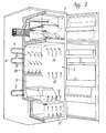
- Figure 2 shows an exploded perspective view of the refrigerator of Figure 1; and
- Figure 3 shows a refrigerator working on a cooling circuit according to the Present invention with the indications pointing out the zones at different temperatures.
- With reference now to Figures from 1 to 3,
numbers - Th cooling circuit of the refrigerating
compartment 1 only will be disclosed, because the realization of the cooling circuit of thecompartment 2 is independent of the object of the present invention. - The static evaporator is made up of a number of series-connected elements. Just two elements are shown in the figure, which are pointed out by the
reference numbers - The compressor of the cooling circuit is housed as usually within the
housing 5 arranged in the back lower zone of the refrigerating compartment. - Combining opportunely the elements of the cooling circuit with the tendency of cold air to become layered towards the bottom space, various temperature combinations can be obtained, one of said combinations which is of special interest being represented in the figures.
- The
element 4 of the evaporator shown in Figure 1 is of such a size as to obtain a temperature of about +5°C within in thezone 6 of thecompartment 1; see also Figure 3. - The
element 3 of said evaporator is in turn of such a size as to obtain an average temperature of about 0°C within thezone 7 of saidcompartment 1. - In order to obtain such temperature in the
zone 7 without oversizing theelement 3, aconveyor wall 8 is arranged parallel to thebottom wall 9 of thecompartment 1, which wall forms a forced way for the flow of cold air descending from thezone 6 as shown by thearrows zone 7 according to arrow 12 (see Figure 2). -
Arrows element 4 within thezone 6 and of the hotter air coming from the bottom space. - In order to obtain a right working of such cooling circuit also with very low working percentages of the compressor it is necessary that the two
elements element 3 is to be fed first, whereas theelement 4 is to be fed after it. - Thus, two zones are obtained within said
compartment 1, the upper zone being at about +5°C whereas the lower zone is at about 0°C, i.e. at the optimal temperatures for storing foodstuffs such as milk, butter, cheese and the like, and meat. - In order to obtain in the lower part of said compartment 1 a zone at an average temperature of about 7°C, which zone is pointed out in the figures by the
reference number 15, it will be sufficient to make theport 16 for the flow from thezone 7 of a suitable size so that a part of cold air conveyed by means of theconveyor wall 8 as well as a part of cold air created by theelement 3 of the static evaporator both flow through saidport 16 instead of following the path pointed out byarrow 11, said airflow going out of the lower part of saidzone 15 following the direction of arrow 17 (see Figure 2). - Thus a zone has been obtained at an average temperature which is optimal for storing fruit and vegetables, with no need for any further element of the static evaporator, just at a point corresponding to the space in which such foodstuffs are stored usually.
Claims (4)
Applications Claiming Priority (2)
| Application Number | Priority Date | Filing Date | Title |
|---|---|---|---|
| IT48657/85A IT1182908B (en) | 1985-10-11 | 1985-10-11 | STATIC EVAPORATOR COOLING CIRCUIT FOR REFRIGERATED TEMPERATURE COMPARTMENT |
| IT4865785 | 1985-10-11 |
Publications (3)
| Publication Number | Publication Date |
|---|---|
| EP0218560A2 EP0218560A2 (en) | 1987-04-15 |
| EP0218560A3 EP0218560A3 (en) | 1988-05-11 |
| EP0218560B1 true EP0218560B1 (en) | 1991-01-23 |
Family
ID=11267875
Family Applications (1)
| Application Number | Title | Priority Date | Filing Date |
|---|---|---|---|
| EP86830280A Expired EP0218560B1 (en) | 1985-10-11 | 1986-10-01 | Refrigerator having refrigerating compartment with zones at different temperatures |
Country Status (4)
| Country | Link |
|---|---|
| EP (1) | EP0218560B1 (en) |
| DE (2) | DE218560T1 (en) |
| ES (1) | ES2002831A6 (en) |
| IT (1) | IT1182908B (en) |
Families Citing this family (4)
| Publication number | Priority date | Publication date | Assignee | Title |
|---|---|---|---|---|
| DE19736916A1 (en) * | 1997-08-25 | 1999-03-04 | Aeg Hausgeraete Gmbh | Electric refrigeration appliance with different temperature storage zones |
| DE10236210A1 (en) | 2002-08-07 | 2004-03-04 | BSH Bosch und Siemens Hausgeräte GmbH | Refrigeration device with divided interior |
| DE102011090175A1 (en) * | 2011-12-30 | 2013-07-04 | BSH Bosch und Siemens Hausgeräte GmbH | Household refrigerator with a cold storage compartment |
| US11402145B1 (en) | 2020-03-24 | 2022-08-02 | Sub-Zero Group, Inc. | Split air flow system |
Family Cites Families (4)
| Publication number | Priority date | Publication date | Assignee | Title |
|---|---|---|---|---|
| US2707871A (en) * | 1952-10-31 | 1955-05-10 | Philco Corp | Refrigeration apparatus |
| CH584874A5 (en) * | 1974-11-22 | 1977-02-15 | Koch Ag | |
| DE2928774C2 (en) * | 1979-07-17 | 1984-03-22 | Bosch-Siemens Hausgeräte GmbH, 7000 Stuttgart | Freezer with a spacious freezer compartment cooled by natural convection |
| GB2079424B (en) * | 1980-07-02 | 1984-11-07 | Thorn Domestic Appliances Ltd | Improvements in or relating to cold cabinets |
-
1985
- 1985-10-11 IT IT48657/85A patent/IT1182908B/en active
-
1986
- 1986-10-01 DE DE198686830280T patent/DE218560T1/en active Pending
- 1986-10-01 DE DE8686830280T patent/DE3677124D1/en not_active Expired - Lifetime
- 1986-10-01 EP EP86830280A patent/EP0218560B1/en not_active Expired
- 1986-10-09 ES ES8602524A patent/ES2002831A6/en not_active Expired
Also Published As
| Publication number | Publication date |
|---|---|
| IT8548657A0 (en) | 1985-10-11 |
| IT1182908B (en) | 1987-10-05 |
| ES2002831A6 (en) | 1988-10-01 |
| EP0218560A2 (en) | 1987-04-15 |
| DE3677124D1 (en) | 1991-02-28 |
| EP0218560A3 (en) | 1988-05-11 |
| DE218560T1 (en) | 1987-09-03 |
Similar Documents
| Publication | Publication Date | Title |
|---|---|---|
| CN100354585C (en) | Freezer | |
| US4775002A (en) | Delivering equipment having heat insulating function which is utilized in delivering articles such as food | |
| US5081850A (en) | Refrigerator | |
| KR940007491A (en) | Refrigerator with Kimchi room | |
| MY119405A (en) | Refrigerator | |
| US2737782A (en) | Plural compartment refrigerator | |
| US3050955A (en) | Multi-temperature refrigerator | |
| US2481616A (en) | Refrigerator | |
| JP5502548B2 (en) | refrigerator | |
| EP0218560A2 (en) | Refrigerator having refrigerating compartment with zones at different temperatures | |
| JPH071138B2 (en) | refrigerator | |
| EP1124101B1 (en) | Refrigerator appliance with refrigeration grid provided with eutectic plates | |
| EP0928934B1 (en) | Domestic refrigerator | |
| KR0139501Y1 (en) | Versatile food storage | |
| JP4557830B2 (en) | refrigerator | |
| JP4179328B2 (en) | Freezer refrigerator | |
| GB2284468A (en) | Refrigeration equipment including a eutectic freezing arrangement | |
| US2787132A (en) | Multi-temperature refrigerator | |
| JP5237598B2 (en) | refrigerator | |
| JP4746018B2 (en) | refrigerator | |
| EP0272761A2 (en) | Upright freezer with selective frost accumulation | |
| JPH11142043A (en) | refrigerator | |
| WO1993014360A1 (en) | Process for preventing the drying up of goods in cold storage rooms | |
| SU589511A1 (en) | Domestic refrigerator | |
| JPH0682022B2 (en) | refrigerator |
Legal Events
| Date | Code | Title | Description |
|---|---|---|---|
| PUAI | Public reference made under article 153(3) epc to a published international application that has entered the european phase |
Free format text: ORIGINAL CODE: 0009012 |
|
| AK | Designated contracting states |
Kind code of ref document: A2 Designated state(s): DE FR GB SE |
|
| EL | Fr: translation of claims filed | ||
| DET | De: translation of patent claims | ||
| PUAL | Search report despatched |
Free format text: ORIGINAL CODE: 0009013 |
|
| AK | Designated contracting states |
Kind code of ref document: A3 Designated state(s): DE FR GB SE |
|
| 17P | Request for examination filed |
Effective date: 19881018 |
|
| 17Q | First examination report despatched |
Effective date: 19890412 |
|
| GRAA | (expected) grant |
Free format text: ORIGINAL CODE: 0009210 |
|
| AK | Designated contracting states |
Kind code of ref document: B1 Designated state(s): DE FR GB SE |
|
| PG25 | Lapsed in a contracting state [announced via postgrant information from national office to epo] |
Ref country code: SE Effective date: 19910123 |
|
| REF | Corresponds to: |
Ref document number: 3677124 Country of ref document: DE Date of ref document: 19910228 |
|
| ET | Fr: translation filed | ||
| PLBE | No opposition filed within time limit |
Free format text: ORIGINAL CODE: 0009261 |
|
| STAA | Information on the status of an ep patent application or granted ep patent |
Free format text: STATUS: NO OPPOSITION FILED WITHIN TIME LIMIT |
|
| 26N | No opposition filed | ||
| REG | Reference to a national code |
Ref country code: GB Ref legal event code: IF02 |
|
| PGFP | Annual fee paid to national office [announced via postgrant information from national office to epo] |
Ref country code: FR Payment date: 20050914 Year of fee payment: 20 |
|
| PGFP | Annual fee paid to national office [announced via postgrant information from national office to epo] |
Ref country code: GB Payment date: 20050928 Year of fee payment: 20 |
|
| PGFP | Annual fee paid to national office [announced via postgrant information from national office to epo] |
Ref country code: DE Payment date: 20051222 Year of fee payment: 20 |
|
| PG25 | Lapsed in a contracting state [announced via postgrant information from national office to epo] |
Ref country code: GB Free format text: LAPSE BECAUSE OF EXPIRATION OF PROTECTION Effective date: 20060930 |
|
| REG | Reference to a national code |
Ref country code: GB Ref legal event code: PE20 |