EP0218505B1 - Energy production installation with several diesel engine cylinders supercharged by reciprocating-piston compressors - Google Patents
Energy production installation with several diesel engine cylinders supercharged by reciprocating-piston compressors Download PDFInfo
- Publication number
- EP0218505B1 EP0218505B1 EP86401989A EP86401989A EP0218505B1 EP 0218505 B1 EP0218505 B1 EP 0218505B1 EP 86401989 A EP86401989 A EP 86401989A EP 86401989 A EP86401989 A EP 86401989A EP 0218505 B1 EP0218505 B1 EP 0218505B1
- Authority
- EP
- European Patent Office
- Prior art keywords
- cylinder
- ports
- motor
- compressor
- cylinders
- Prior art date
- Legal status (The legal status is an assumption and is not a legal conclusion. Google has not performed a legal analysis and makes no representation as to the accuracy of the status listed.)
- Expired
Links
Images


Classifications
-
- F—MECHANICAL ENGINEERING; LIGHTING; HEATING; WEAPONS; BLASTING
- F02—COMBUSTION ENGINES; HOT-GAS OR COMBUSTION-PRODUCT ENGINE PLANTS
- F02B—INTERNAL-COMBUSTION PISTON ENGINES; COMBUSTION ENGINES IN GENERAL
- F02B75/00—Other engines
- F02B75/04—Engines with variable distances between pistons at top dead-centre positions and cylinder heads
-
- F—MECHANICAL ENGINEERING; LIGHTING; HEATING; WEAPONS; BLASTING
- F02—COMBUSTION ENGINES; HOT-GAS OR COMBUSTION-PRODUCT ENGINE PLANTS
- F02B—INTERNAL-COMBUSTION PISTON ENGINES; COMBUSTION ENGINES IN GENERAL
- F02B33/00—Engines characterised by provision of pumps for charging or scavenging
- F02B33/44—Passages conducting the charge from the pump to the engine inlet, e.g. reservoirs
-
- F—MECHANICAL ENGINEERING; LIGHTING; HEATING; WEAPONS; BLASTING
- F02—COMBUSTION ENGINES; HOT-GAS OR COMBUSTION-PRODUCT ENGINE PLANTS
- F02B—INTERNAL-COMBUSTION PISTON ENGINES; COMBUSTION ENGINES IN GENERAL
- F02B71/00—Free-piston engines; Engines without rotary main shaft
- F02B71/04—Adaptations of such engines for special use; Combinations of such engines with apparatus driven thereby
- F02B71/06—Free-piston combustion gas generators per se
-
- F—MECHANICAL ENGINEERING; LIGHTING; HEATING; WEAPONS; BLASTING
- F02—COMBUSTION ENGINES; HOT-GAS OR COMBUSTION-PRODUCT ENGINE PLANTS
- F02B—INTERNAL-COMBUSTION PISTON ENGINES; COMBUSTION ENGINES IN GENERAL
- F02B3/00—Engines characterised by air compression and subsequent fuel addition
- F02B3/06—Engines characterised by air compression and subsequent fuel addition with compression ignition
Definitions
- the invention relates to energy production installations comprising at least one diesel engine with several cylinders operating sequentially, supercharged by several reciprocating compressors supplying the purge air to the engine.
- Diesel engines are generally supercharged by a rotary compressor or an alternating compressor whose cylinders operate in an offset manner.
- all the cylinders emerge in the same manifold. Consequently, the scanning of the engine cylinders is carried out at a substantially constant intake pressure.
- a thermodynamic study of the phenomena which occur during the sweeping shows that the compression work with transfer depends directly on the difference between the average inlet pressure of the sweeping air and the exhaust pressure. Consequently, the work during transfer is determined by the average pressure in the manifold, and not by the discharge pressure of a particular compressor cylinder. It should however be noted that this is only true in the case of an engine and a compressor having several cylinders. In the case of an installation having a single engine cylinder supplied by a single compressor cylinder (such as that described in the document FR-A-1 238 426), the situation is completely different since there is no manifold for mixture feeding several cylinders.
- FIG. 1 of GB-A-1 116 162 An installation is known according to the preamble of claim 1.
- the installation of this type described in FIG. 1 of GB-A-1 116 162 comprises several driving cylinders.
- Each engine cylinder has a row of intake and sweep lights, powered by a capacity that receives compressed air from two compressor cylinders, each located on one side of a compressor piston. Because of this arrangement, the intake capacity acts as a collector causing the engine cylinder to sweep at substantially constant intake pressure, with the drawbacks exposed above.
- the invention aims in particular to provide an installation in which this work is significantly reduced. To this end, it proposes an installation according to the characterizing part of claim 1.
- the scanning is carried out at a gradually decreasing intake pressure, which reduces the work performed.
- the gain thus obtained can be further increased by providing the exhaust pipes of the engine cylinder with a constant section close to the lights, then a slowly increasing section, which makes it possible to cause a rapid drop in the pressure in the engine cylinder, first up to a value of the order of 1.5 Pe (Pe being the pressure prevailing in an exhaust capacity), then up to a value lower than the pressure prevailing in the exhaust capacity, from made of creating a depression wave.
- the vacuum in the cylinder may remain until the piston returns until the intake ports are closed.
- the invention finds a particularly important application in installations comprising a gas generator with free pistons of the multi-tandem type, associated with a gas turbine.
- the generator comprises engine cylinders operating according to a Diesel cycle, belonging to two groups operating in phase opposition, and compressor cylinders also divided into two groups.
- This solution has many advantages over those adopted previously when a large fraction of the air flow supplied by the compressors is used for sweeping the motors. However, this interest diminishes as a larger fraction of the flow is used to directly feed the gas turbine.
- each engine cylinder delimited by two engine pistons, from a single compressor compartment, chosen so that the delivery stroke coincides with the moment when the lights of the corresponding engine are closed.
- the provisions defined above make it possible to significantly reduce the work of the exhaust gases. They can be implemented on a driving cylinder comprising conventional type scanning lights. It is known that, depending on whether the scanning lights are designed so as to provide a radial air jet or an air jet having a tangential component, the flow during the first phase of the scanning takes place according to a different regime . In the first case, the flow of fresh sweeping air is in the form of a central jet, surrounded by an annular wake of hot combustion gases. This solution has the advantage of ensuring efficient scanning. But there is no rotational movement of the fresh gases in the engine.
- the invention also aims to provide an installation whose scanning means allow obtain the favorable effects of the rotary movement while ensuring an interesting sweeping of the entire engine cylinder.
- the invention in particular proposes an installation in which each engine cylinder comprises scanning lights distributed regularly around the cylinder at one end of the latter and exhaust means, such as lights, also regularly distributed at the other end of the cylinder delimited by two pistons moving in opposite directions, said scanning lights being distributed in two successively uncovered rows, the lights of the row discovered first being arranged so as to provide a jet having a tangential component while the lights second discoveries are provided to provide a jet directed substantially towards the axis.
- the two rows are supplied by the same intake capacity, but means are advantageously provided for delaying the arrival of purge air at the lights of the first row. This result can in particular be achieved by providing a winding path or a secondary capacity between a main intake capacity (which directly feeds the lights of the second set) and the lights of the first set.
- the first row of lights providing a jet oriented for example at 30 ° with respect to the radial direction, establishes a flow of peripheral annular type animated with a high speed of rotation.
- the second row causes the appearance of a central jet without rotation ensuring efficient scanning.
- each compressor cylinder In a multitandem gas generator installation, each compressor cylinder, or at least each compression chamber, has so far been assigned to a determined flow.
- certain compressor cylinders provide a primary air flow intended for the engine, while others supply the secondary air flow intended for the turbine.
- the sweep ratio (that is to say the ratio between the quantity of air passing through the motors and the displacement of these motors) is fixed or, at least, can only be modified by important steps.
- the invention also aims to provide means for more precise adaptation of the scanning ratio to the needs of scanning of the kind defined above.
- the invention also proposes to assign some of the compressors of the installation to a single flow and other cylinders to two flows, by providing discharge valves opening into two separate manifolds assigned, one to the flow. primary, the other to secondary flow.
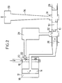
- FIGS. 1 to 3 there will be described an operating cycle of an assembly comprising only an engine cylinder 10 and a compressor cylinder 12 of a gas generator with free pistons which may have the general constitution described.
- the compressor cylinder 12 contains a piston 14 separating a compression compartment 16 assigned to the primary flow and a compartment 18 assigned to the secondary flow and directly supplying a gas turbine not shown.
- the compartment 16 is provided with valves 20 for intake of fresh air and with valves 22 for delivery to an intake capacity 24.
- the piston 14 is mechanically coupled to a driving piston 26 delimiting, with a symmetrical piston 28, a compartment motor 30 which, in the position of maximum separation of the pistons 26 and 28, has a volume equal to about one fifth of the volume of the capacity 24.
- the piston 26 cooperates with scanning lights 32 while the piston 28 cooperates with exhaust lights 34 opening into a pipe 36 supplying an exhaust capacity 38 connected to a high turbine pressure (not shown).
- Figure 1 shows in solid lines the position of the movable assembly comprising the pistons 14, 26 and 28 at the time of opening of the exhaust lights 34, that is to say when the puff occurs exhaust. Due to the difference in location of lights 32 and 34, the scanning lights are still closed.
- the engine pistons move away from each other.
- the compression chamber 16 is in suction, the piston 14 moving away from the plate which carries the valves 20 and 22.
- Pc In the intake capacity there prevails a pressure Pc, while the pressure in the compressor compartment 16 is substantially equal to the inlet pressure Pa.
- the pressure prevailing in the engine cylinder 30 is substantially equal to 3Pi.
- the engine pistons then uncover the scanning lights 32, as indicated in dashes in FIG. 1.
- the intake capacity 24 is then in connection with the engine cylinder 30. As soon as the exhaust puff has released the pressure which prevails in the engine below Pc, the intake capacity 24 begins to discharge into the engine to sweep it (dashed arrow in Figure 1).
- the compression phase in the engine and the discharge from the compressor 12 to the intake capacity 24 then begins.
- the pistons 26 and 28 in dashes in Figure 2
- the pistons 26 and 28 successively close the scanning lights 32 then the exhaust lights 34, isolating the engine from the intake capacity .
- the compressor 12 during this time charges the intake capacity whose pressure rises.
- Figure 5 on which the elements corresponding to those of Figure 1 are designated by the same reference number, shows an intake capacity 24 formed in the cylinder housing 30 and communicating directly with a row of intake lights 32 2 which open radially into the cylinder ( Figure 6).
- Another row of lights 32 "placed so as to be discovered first by the piston 26 during the rebound stroke, are, on the contrary, oriented obliquely, with an angle relative to the radial plane which will generally be approximately 30 ° ( Figure 7).
- the arrangement shown in FIG. 5 acts on two factors. On the one hand, it tends to decrease the total pressure of the peripheral fluid threads, supplied by the lights 32" by decreasing their speed. On the other hand, it delays the appearance of the effective flow through these lights 32 1 . These two results are achieved by having, between the intake capacity 24 and the lights 32 "a pipe 40 in baffles, of small volume but of length much greater than the axial interval between the rows 32, and 32 2 , This pipe phase out the flow and cause a pressure drop which reduces the total supply pressure.
- the presence of the two rows of lights and of the pipe 40 brings other favorable results.
- the total length of the scanning and intake lights 32 1 - 32 2 can be increased by approximately 30% for the same useful displacement.
- the phase shift of the flow by the lights 32 1 flattens the tip of the peripheral fresh air front.
- the pressure drops in the pipe 40 are used.
- a pressure drop of the same order as that caused by the lights 32 1 will be used , which reduces the speed at which the lights pass through.
- a ratio which corresponds approximately to that of the distances traveled by the peripheral air streams and close to the axis.
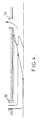
- Figure 8 shows the results of a simulation carried out to determine the fronts of invasion of the cylinder 30 by the fresh air when the lights are of the kind shown in Figure 5.
- the curves identified by the references 1, 2, 3, 4 and 5 show the edges respectively 2 ms, 6 ms, 10 ms, 16 ms and 20 ms after the start of opening of the second row of lights.
- valves with delayed controlled opening or calibrated valves with automatic opening interposed between the intake capacity and the lights 321 of the first set are possible, in particular the use of valves with delayed controlled opening or calibrated valves with automatic opening interposed between the intake capacity and the lights 321 of the first set.
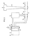
- FIG. 9 shows only two compressors among the eight that include such a generator.
- the compressor 42 is intended to supply only air to the secondary circuit, via a heat exchanger 44 intended to heat it.
- the air having passed through the exchanger 44 is sent to a high pressure gas turbine 46.
- At least one other compressor cylinder 12, or at least the other compartment delimited by the compressor piston 14 in the cylinder 12, is mixed in the sense that it supplies air to the primary circuit, which includes a cooler 48 and opens out. in an engine cylinder 30, and in the secondary circuit.
- the delivery manifold 50 of the cylinder 12 is separated by a partition 52 into two chambers. In each chamber, several discharge valves 22 of the compressor open. Since the number of these valves is high, often between ten and twenty, there is thus an extremely flexible adjustment mode.
Abstract
Description
L'invention concerne les installations de production d'énergie comprenant au moins un moteur Diesel à plusieurs cylindres fonctionnant séquentiellement, suralimenté par plusieurs compresseurs alternatifs fournissant l'air de balayage au moteur.The invention relates to energy production installations comprising at least one diesel engine with several cylinders operating sequentially, supercharged by several reciprocating compressors supplying the purge air to the engine.
Les moteurs Diesel sont généralement suralimentés par un compressuer rotatif ou un compresseur alternatif dont les cylindres fonctionnent de façon décalée. Dans le second cas, tous les cylindres débouchent dans un même collecteur. En conséquence, le balayage des cylindres moteurs s'effectue à pression d'admission sensiblement constante. Une étude thermodynamique des phénomènes qui interviennent au cours du balayage montre que le travail de compression avec transvasement dépend directement de la différence entre la pression moyenne d'admission de l'air de balayage et la pression d'échappement. En conséquence, le travail lors du transvasement est déterminé par la pression moyenne dans le collecteur, et non pas par la pression de refoulement d'un cylindre compresseur particulier. Il faut cependant remarquer que cela n'est vrai que dans le cas d'un moteur et d'un compresseur ayant plusieurs cylindres. Dans le cas d'une installation ayant un cylindre moteur unique alimenté par un seul cylindre compresseur (comme celle décrite dans le document FR-A-1 238 426), la situation est totalement différente puisqu'il n'y a pas de collecteur de mélange alimentant plusieurs cylindres.Diesel engines are generally supercharged by a rotary compressor or an alternating compressor whose cylinders operate in an offset manner. In the second case, all the cylinders emerge in the same manifold. Consequently, the scanning of the engine cylinders is carried out at a substantially constant intake pressure. A thermodynamic study of the phenomena which occur during the sweeping shows that the compression work with transfer depends directly on the difference between the average inlet pressure of the sweeping air and the exhaust pressure. Consequently, the work during transfer is determined by the average pressure in the manifold, and not by the discharge pressure of a particular compressor cylinder. It should however be noted that this is only true in the case of an engine and a compressor having several cylinders. In the case of an installation having a single engine cylinder supplied by a single compressor cylinder (such as that described in the document FR-A-1 238 426), the situation is completely different since there is no manifold for mixture feeding several cylinders.
On connaît une installation suivant le préambule de la revendication 1. L'installation de ce type décrite en figure 1 du GB-A-1 116 162 comporte plusieurs cylindres moteurs. Chaque cylindre moteur comporte une rangée de lumières d'admission et de balayage, alimentées par une capacité qui reçoit de l'air comprimé provenant de deux cylindres compresseurs, situés chacun d'un côté d'un piston compresseur. Du fait de cette disposition, la capacité d'admission joue un rôle de collecteur provoquant le balayage du cylindre moteur à pression d'admission sensiblement constante, avec les inconvénients exposés plus haut.An installation is known according to the preamble of
L'invention vise notamment à fournir une installation dans laquelle ce travail est notablement réduit. Dans ce but, elle propose une installation suivant la partie caractérisante de la revendication 1.The invention aims in particular to provide an installation in which this work is significantly reduced. To this end, it proposes an installation according to the characterizing part of
Grâce à cette disposition, le balayage s'effectue à pression d'admission progressivement décroissante, ce qui réduit le travail effectué. Le gain ainsi obtenu peut être encore accru en prévoyant les conduits d'échappement du cylindre moteur avec une section constante près des lumières, puis une section lentement croissante, ce qui permet de provoquer une chute rapide de la pression dans le cylindre moteur, d'abord jusqu'à une valeur de l'ordre de 1,5 Pe (Pe étant la pression qui règne dans une capacité d'échappement), puis jusqu'à une valeur inférieure à la pression qui règne dans la capacité d'échappement, du fait de la création d'une onde de dépression. La dépression dans le cylindre peut subsister jusqu'à retour du piston jusqu'à fermeture des lumières d'admission.Thanks to this arrangement, the scanning is carried out at a gradually decreasing intake pressure, which reduces the work performed. The gain thus obtained can be further increased by providing the exhaust pipes of the engine cylinder with a constant section close to the lights, then a slowly increasing section, which makes it possible to cause a rapid drop in the pressure in the engine cylinder, first up to a value of the order of 1.5 Pe (Pe being the pressure prevailing in an exhaust capacity), then up to a value lower than the pressure prevailing in the exhaust capacity, from made of creating a depression wave. The vacuum in the cylinder may remain until the piston returns until the intake ports are closed.
L'invention trouve une application particulièrement importante dans les installations comprenant un générateur de gaz à pistons libres du type multi-tandem, associé à une turbine à gaz. Le générateur comprend des cylindres moteurs fonctionnant suivant un cycle Diesel, appartenant à deux groupes fonctionnant en opposition de phase, et des cylindres compresseurs également répartis en deux groupes. On a déjà proposé (EP-A-7874) de spécialiser les compresseurs de façon que certains cylindres compresseurs fournissent un flux primaire alimentant les moteurs et d'autres un flux secondaire alimentant une turbine à gaz en même temps que les gaz d'échappement des cylindres moteurs. Cette solution présente de nombreux avantages sur celles adoptées antérieurement lorsqu'une fraction importante du débit d'air fourni par les compresseurs est utilisée pour le balayage des moteurs. Mais cet intérêt s'atténue au fur à mesure que l'on utilise une fraction plus importante du débit pour alimenter directement la turbine à gaz. Il devient alors plus intéressant d'adopter la solution suivant l'invention définie ci-dessus, ce qui est d'autant plus facile que l'on peut affecter une chambre de compression à chaque cylindre moteur. En particulier, il est possible d'alimenter chaque cylindre moteur, délimité par deux pistons moteurs, à partir d'un seul compartiment de compresseur, choisi de façon que la course de refoulement coïncide avec le moment où les lumières du moteur correspondant sont fermées.The invention finds a particularly important application in installations comprising a gas generator with free pistons of the multi-tandem type, associated with a gas turbine. The generator comprises engine cylinders operating according to a Diesel cycle, belonging to two groups operating in phase opposition, and compressor cylinders also divided into two groups. It has already been proposed (EP-A-7874) to specialize compressors so that certain compressor cylinders provide a primary flow supplying the engines and others a secondary flow supplying a gas turbine at the same time as the exhaust gases of the engine cylinders. This solution has many advantages over those adopted previously when a large fraction of the air flow supplied by the compressors is used for sweeping the motors. However, this interest diminishes as a larger fraction of the flow is used to directly feed the gas turbine. It then becomes more advantageous to adopt the solution according to the invention defined above, which is all the easier as one can assign a compression chamber to each engine cylinder. In particular, it is possible to supply each engine cylinder, delimited by two engine pistons, from a single compressor compartment, chosen so that the delivery stroke coincides with the moment when the lights of the corresponding engine are closed.
Les dispositions ci-dessus définies permettent de diminuer notablement le travail des gaz à l'échappement. Elles peuvent être mises en oeuvre sur un cylindre moteur comportant des lumières de balayage de type classique. On sait que, suivant que les lumières de balayage sont dessinées de façon à fournir un jet d'air radial ou un jet d'air présentant une composante tangentielle, l'écoulement lors de la première phase du balayage s'effectue suivant un régime différent. Dans le premier cas, l'écoulement d'air frais de balayage se fait sous forme d'un jet central, entouré d'un sillage annulaire de gaz de combustion chauds. Cette solution a l'avantage de garantir un balayage efficace. Mais il n'y a pas de mouvement de rotation des gaz frais dans le moteur. Au contraire, lorsque les lumières sont inclinées, l'air frais se répartit suivant une nappe annulaire stable, en rotation, entourant un noyau de gaz chauds: le mouvement de rotation subsiste lors du début de la combustion et est favorable à cette dernière. Mais en contrepartie, le balayage n'intéresse plus la partie centrale du cylindre et il est peu efficace.The provisions defined above make it possible to significantly reduce the work of the exhaust gases. They can be implemented on a driving cylinder comprising conventional type scanning lights. It is known that, depending on whether the scanning lights are designed so as to provide a radial air jet or an air jet having a tangential component, the flow during the first phase of the scanning takes place according to a different regime . In the first case, the flow of fresh sweeping air is in the form of a central jet, surrounded by an annular wake of hot combustion gases. This solution has the advantage of ensuring efficient scanning. But there is no rotational movement of the fresh gases in the engine. On the contrary, when the lights are tilted, the fresh air is distributed in a stable annular sheet, in rotation, surrounding a core of hot gases: the rotational movement remains at the start of combustion and is favorable to the latter. On the other hand, the scanning no longer concerns the central part of the cylinder and it is not very effective.
L'invention vise également à fournir une installation dont les moyens de balayage permettent d'obtenir les effets favorables du mouvement rotatoire tout en assurant un balayage intéressant l'ensemble du cylindre moteur. Dans ce but, l'invention propose notamment une installation dont chaque cylindre moteur comporte des lumières de balayage réparties régulièrement autour du cylindre à une extrémité de celui-ci et des moyens d'échappement, tels que des lumières, également répartis régulièrement à l'autre extrémité du cylindre délimité par deux pistons se déplaçant en sens inverse, lesdites lumières de balayage étant réparties en deux rangées successivement découvertes, les lumières de la rangée découverte en premier étant disposées de façon à fournir un jet ayant une composante tangentielle tandis que les lumières découvertes en second sont prévues pour fournir un jet dirigé sensiblement vers l'axe.The invention also aims to provide an installation whose scanning means allow obtain the favorable effects of the rotary movement while ensuring an interesting sweeping of the entire engine cylinder. To this end, the invention in particular proposes an installation in which each engine cylinder comprises scanning lights distributed regularly around the cylinder at one end of the latter and exhaust means, such as lights, also regularly distributed at the other end of the cylinder delimited by two pistons moving in opposite directions, said scanning lights being distributed in two successively uncovered rows, the lights of the row discovered first being arranged so as to provide a jet having a tangential component while the lights second discoveries are provided to provide a jet directed substantially towards the axis.
Les deux rangées sont alimentées par une même capacité d'admission, mais des moyens sont avantageusement prévus pour retarder l'arrivée d'air de balayage aux lumières de la première rangée. Ce résultat peut notamment être atteint en prévoyant un trajet sinueux ou une capacité secondaire entre une capacité d'admission principale (qui alimente directement les lumières du second jeu) et les lumières du premier jeu.The two rows are supplied by the same intake capacity, but means are advantageously provided for delaying the arrival of purge air at the lights of the first row. This result can in particular be achieved by providing a winding path or a secondary capacity between a main intake capacity (which directly feeds the lights of the second set) and the lights of the first set.
Dans ces conditions, la première rangée de lumières, fournissant un jet orienté par exemple à 30° par rapport à la direction radiale, établit un écoulement de type annulaire périphérique animé d'une vitesse de rotation importante. La seconde rangée provoque l'apparition d'un jet central sans rotation assurant un balayage efficace. Au cours du balayage et de la compression ultérieure, il y a entraînement progressif du noyau central de gaz frais par l'écoulement périphérique en rotation, ce qui permet d'arriver finalement à une masse d'air en rotation en bloc à une vitesse plus réduite que dans les moteurs antérieurs, mais conservant l'effet favorable recherché sur la combustion.Under these conditions, the first row of lights, providing a jet oriented for example at 30 ° with respect to the radial direction, establishes a flow of peripheral annular type animated with a high speed of rotation. The second row causes the appearance of a central jet without rotation ensuring efficient scanning. During the sweeping and the subsequent compression, there is a progressive entrainment of the central core of fresh gas by the rotating peripheral flow, which makes it possible finally to arrive at a mass of air in rotation in block at a higher speed. reduced than in previous engines, but retaining the desired favorable effect on combustion.
Par ailleurs, lorsque deux rangées de lumières de balayage sont prévues, il est avantageux de disposer des moyens retardant, et éventuellement ralentissant, l'arrivée d'air frais par les lumières de la première rangée, on peut ainsi donner au front d'air frais qui se propage le long du cylindre vers les lumières d'échappement, une allure se rapprochant davantage d'un front perpendiculaire à l'axe.Furthermore, when two rows of scanning lights are provided, it is advantageous to have means delaying, and possibly slowing down, the arrival of fresh air by the lights of the first row, it is thus possible to give the air front cool which propagates along the cylinder towards the exhaust lights, a gait closer to a front perpendicular to the axis.
Dans une installation à générateur de gaz multitandem, on a jusqu'à présent affecté chaque cylindre compresseur, ou du moins chaque chambre de compression, à un flux déterminé. Par exemple, dans le document EP-A-7874 déjà cité, certains cylindres compresseurs fournissent un flux d'air primaire destiné au moteur, tandis que d'autres fournissent le flux d'air secondaire destiné à la turbine. Mais, dans ces conditions, le rapport de balayage (c'est-à-dire le rapport entre la quantité d'air qui traverse les moteurs et la cylindrée de ces moteurs) est fixe ou, du moins, ne peut être modifié que par échelons importants. L'invention vise encore à fournir des moyens d'adaptation plus précise du rapport de balayage aux besoins de balayages du genre ci-dessus défini. Dans ce but, l'invention propose encore d'affecter certains des compresseurs de l'installation à un seul flux et d'autres cylindres à deux flux, en prévoyant des clapets de refoulement débouchant dans deux collecteurs distincts affectés, l'un au flux primaire, l'autre au flux secondaire.In a multitandem gas generator installation, each compressor cylinder, or at least each compression chamber, has so far been assigned to a determined flow. For example, in the document EP-A-7874 already cited, certain compressor cylinders provide a primary air flow intended for the engine, while others supply the secondary air flow intended for the turbine. However, under these conditions, the sweep ratio (that is to say the ratio between the quantity of air passing through the motors and the displacement of these motors) is fixed or, at least, can only be modified by important steps. The invention also aims to provide means for more precise adaptation of the scanning ratio to the needs of scanning of the kind defined above. To this end, the invention also proposes to assign some of the compressors of the installation to a single flow and other cylinders to two flows, by providing discharge valves opening into two separate manifolds assigned, one to the flow. primary, the other to secondary flow.
L'invention sera mieux comprise à la lecture de la description qui suit de modes particuliers d'exécution, donnés à titre d'exemples non limitatifs. La description se réfère aux dessins qui l'accompagnent, dans lesquels:
- - les Figures 1, 2 et 3 sont des schémas montrant, à divers stades du cycle de fonctionnement, la disposition des composants d'un cylindre moteur et d'un cylindre compresseur d'une installation suivant un mode de réalisation de l'invention,
- - la Figure 4 est un schéma, en coupe suivant un plan passant par l'axe longitudinal d'un cylindre moteur, montrant la modification du front de propagation des gaz de balayage obtenue grâce à l'invention,
- - la Figure 5 est un schéma à grande échelle, en coupe suivant un plan passant par l'axe d'un cylindre moteur, montrant une disposition possible des lumières de balayage,
- - les Figures 6 et 7 montrent l'orientation des lumières de balayage des deux rangées illustrées en Figure 5,
- - la Figure 8 est un schéma montrant la propagation des fronts de balayage dans un cylindre moteur équipé de lumières du type montré en Figures 5 à 7,
- - la Figure 9 est un schéma de principe montrant deux des compresseurs d'une installation à générateur de gaz à pistons libres, l'un des deux cylindres compresseurs étant mixte en ce sens qu'il est affecté, d'une part, au circuit d'air primaire, d'autre part, au circuit d'air secondaire.
- FIGS. 1, 2 and 3 are diagrams showing, at various stages of the operating cycle, the arrangement of the components of a driving cylinder and of a compressor cylinder of an installation according to an embodiment of the invention,
- FIG. 4 is a diagram, in section along a plane passing through the longitudinal axis of a driving cylinder, showing the modification of the propagation front of the sweeping gases obtained thanks to the invention,
- FIG. 5 is a large-scale diagram, in section along a plane passing through the axis of a driving cylinder, showing a possible arrangement of the scanning lights,
- FIGS. 6 and 7 show the orientation of the scanning lights of the two rows illustrated in FIG. 5,
- FIG. 8 is a diagram showing the propagation of the scanning fronts in an engine cylinder fitted with lights of the type shown in FIGS. 5 to 7,
- - Figure 9 is a block diagram showing two of the compressors of an installation with a gas generator with free pistons, one of the two compressor cylinders being mixed in the sense that it is assigned, on the one hand, to the circuit primary air, on the other hand, to the secondary air circuit.
On décrira tout d'abord, en faisant référence aux Figures 1 à 3, un cycle de fonctionnement d'un ensemble comprenant uniquement un cylindre moteur 10 et un cylindre compresseur 12 d'un générateur de gaz à pistons libres pouvant avoir la constitution générale décrite dans le document EP-A-7874 déjà-mentionné. Le cylindre compresseur 12 contient un piston 14 séparant un compartiment de compression 16 affecté au flux primaire et un compartiment 18 affecté au flux secondaire et alimentant directement une turbine à gaz non représentée. Le compartiment 16 est muni de clapets 20 d'admission d'air frais et de clapets 22 de refoulement vers une capacité d'admission 24. Le piston 14 est mécaniquement couplé à un piston moteur 26 délimitant, avec un piston symétrique 28, un compartiment moteur 30 qui, dans la position d'écartement maximal des pistons 26 et 28, présente un volume égal à environ un cinquième du volume de la capacité 24. Le piston 26 coopère avec des lumières de balayage 32 tandis que le piston 28 coopère avec des lumières d'échappement 34 débouchant dans une pipe 36 alimentant une capacité d'échappement 38 reliée à une turbine haute pression (non représentée).Firstly, with reference to FIGS. 1 to 3, there will be described an operating cycle of an assembly comprising only an
La Figure 1 montre en traits pleins la position de l'équipage mobile comprenant les pistons 14, 26 et 28 à l'instant d'ouverture des lumières d'échappement 34, c'est-à-dire au moment où se produit la bouffée d'échappement. Etant donné la différence d'emplacement des lumières 32 et 34, les lumières de balayage sont encore fermées. Les pistons moteurs s'éloignent l'un de l'autre. La chambre de compression 16 est en aspiration, le piston 14 s'éloignant de la plaque qui porte les clapets 20 et 22. Dans la capacité d'admission règne une pression Pc, alors que la pression dans le compartiment compresseur 16 est sensiblement égale à la pression d'admission Pa. La pression qui règne dans le cylindre moteur 30 est sensiblement égale à 3Pi.Figure 1 shows in solid lines the position of the movable assembly comprising the
Moyennant un dessin approprié des lumières d'échappement 34 et de leur raccordement avec la pipe 36, la pression totale à l'entrée des pipes augmente alors rapidement et atteint une valeur d'environ 1,5 Pe.By means of an appropriate design of the exhaust lights 34 and of their connection with the
Les pistons moteurs découvrent ensuite les lumières de balayage 32, comme indiqué en tirets sur la Figure 1. La capacité d'admission 24 est alors en liaison avec le cylindre moteur 30. Dès que la bouffée d'échappement a fait retomber la pression qui règne dans le moteur au-dessous de Pc, la capacité d'admission 24 commence à se décharger dans le moteur pour le balayer (flèche en tirets sur la Figure 1).The engine pistons then uncover the scanning lights 32, as indicated in dashes in FIG. 1. The
Ce processus de balayage se poursuit jusqu'à ce que les équipages mobiles aient atteint leur maximum de course, c'est-à-dire le point mort extérieur, comme indiqué en trait plein sur la Figure 2. Le mouvement des équipages mobiles s'inverse, comme indiqué par les flèches f. Le balayage du moteur se poursuit comme indiqué par les flèches F. La capacité d'admission 24 est toujours en communication avec le moteur et isolée du compresseur.This scanning process continues until the moving parts have reached their maximum travel, that is to say the external dead center, as indicated in solid lines in Figure 2. The movement of the moving parts reverse, as indicated by the arrows f. The engine scanning continues as indicated by the arrows F. The
La phase de compression dans le moteur et de refoulement du compresseur 12 vers la capacité d'admission 24 commence alors. Au cours du mouvement de rapprochement des pistons moteurs 26 et 28 (en tirets sur la Figure 2), les pistons 26 et 28 ferment successivement les lumières de balayage 32 puis les lumières d'échappement 34, isolant le moteur de la capacité d'admission. Le compresseur 12 charge pendant ce temps la capacité d'admission dont la pression remonte.The compression phase in the engine and the discharge from the
Lorsque les pistons moteurs arrivent au point mort intérieur, leur mouvement commence à s'inverser, le combustible est injecté dans le moteur et la combustion commence.When the engine pistons come to internal dead center, their movement begins to reverse, the fuel is injected into the engine and combustion begins.
Enfin, la détente du moteur a lieu en même temps que celle de l'espace mort du compresseur tandis que la capacité d'admission 24 se trouve en attente de décharge (Figure 3) et le cycle reprend.Finally, the expansion of the engine takes place at the same time as that of the dead space of the compressor while the
Que le balayage s'effectue à pression d'admission constante ou à pression variable, l'utilisation d'une disposition traditionnelle des lumières laisse subsister les inconvénients déjà signalés, à savoir le caractère incomplet du balayage en cas d'injection d'un jet tangentiel, l'absence de mouvement rotatoire favorable à la combustion en cas de jets radiaux.Whether the sweeping is carried out at constant inlet pressure or at variable pressure, the use of a traditional arrangement of lights allows the drawbacks already mentioned to remain, namely the incomplete nature of the sweeping in the event of a jet injection. tangential, the absence of rotary movement favorable to combustion in the event of radial jets.
On pourrait penser qu'il est possible d'écarter la difficulté en donnant aux lumières de balayage une forme vrillée, de sorte que l'injection s'effectue avec une composante tangentielle dans la partie des lumières les plus proches du plan médian, radialement dans la partie la plus éloignée du plan médian. Mais, indépendamment des difficultés de réalisation de telles lumières, un problème supplémentaire subsiste, dû à la différence de parcours des différents filets d'air. Cette différence de parcours fait que, lorsque le front d'air frais atteint les lumières de balayage, il présente une forme du genre montré en trait plein sur la Figure 4, laissant subsister un noyau de gaz brûlés qui risque de se trouver piégé dans le cylindre.One might think that it is possible to avoid the difficulty by giving the scanning lights a twisted shape, so that the injection takes place with a tangential component in the part of the lights closest to the median plane, radially in the part furthest from the median plane. However, regardless of the difficulties in producing such lights, an additional problem remains, due to the difference in the course of the different air streams. This difference in path means that, when the fresh air front reaches the scanning lights, it presents a shape of the kind shown in solid lines in FIG. 4, leaving a core of burnt gases which may be trapped in the cylinder.
On décrira maintenant un système de balayage à deux rangées de lumières, permettant dans tous les cas d'associer les avantages du balayage radial au balayage rotatif et permettant par ailleurs, au prix d'aménagements simples, de modifier le front d'écoulement de façon à lui donner une allure du genre illustré en tirets sur la Figure 4.We will now describe a scanning system with two rows of lights, allowing in any case to combine the advantages of radial scanning with rotary scanning and also allowing, at the cost of simple arrangements, to modify the flow front so to give it a look like the one shown in dashes in Figure 4.
La Figure 5, sur laquelle les éléments correspondant à ceux de la Figure 1 sont désignés par le même numéro de référence, montre une capacité d'admission 24 ménagée dans le carter du cylindre 30 et communiquant directement avec une rangée de lumières d'admission 322 qui débouchent radialement dans le cylindre (Figure 6). Une autre rangée de lumières 32" placées de façon à être découvertes les premières par le piston 26 lors de la course de détente, sont au contraire orientées obliquement, avec un angle par rapport au plan radial qui sera généralement d'environ 30° (Figure 7).Figure 5, on which the elements corresponding to those of Figure 1 are designated by the same reference number, shows an
Pour réduire l'avance relative des filets fluides provenant des lumières 32" la disposition montrée en Figure 5 agit sur deux facteurs. D'une part, elle tend à diminuer la pression totale des filets fluides périphériques, fournis par les lumières 32" en diminuant leur vitesse. D'autre part, elle retarde l'apparition de l'écoulement effectif à travers ces lumières 321. Ces deux résultats sont atteints en disposant, entre la capacité d'admission 24 et les lumières 32" une conduite 40 en chicanes, de faible volume mais de longueur très supérieure à l'intervalle axial entre les rangées 32, et 322, Cette conduite déphase l'écoulement et provoque une perte de charge qui réduit la pression totale d'alimentation.To reduce the relative advance of the fluid threads coming from the 32 "lights, the arrangement shown in FIG. 5 acts on two factors. On the one hand, it tends to decrease the total pressure of the peripheral fluid threads, supplied by the
Grâce à cette disposition, il se produit, à l'ouverture des lumières 321, un léger refoulement du moteur vers l'admission. Les mélanges entre air froid de balayage et gaz brûlés sont limités au cours de ce refoulement par le grand allongement relatif de la conduite 40.Thanks to this arrangement, there is a slight backflow from the engine towards the intake when the
Les dimensions de la conduite 40 dépendront des paramètres de chaque installation particulière. Mais elles obéiront aux règles suivantes:
- - la longueur de la conduite 40 est déterminée pour que la différence entre la pression dans la capacité d'admission 24 et la pression dans le moteur ait changé de signe quand l'onde de détente due à la réflexion de l'onde de compression à l'extrémité de la conduite 40 arrive
aux lumières 321, ce qui limite le débit refoulé, - - la durée d'aller-retour des ondes doit être telle que le
piston 26 ait découvert toute la longueur des lumières 321 à l'instant de retour, - - le début d'ouverture des lumières 322 doit intervenir lorsque la masse de gaz admise dans le moteur par les lumières 321 est du même ordre de grandeur que la masse initialement refoulée du moteur vers la conduite 40.
- the length of the
pipe 40 is determined so that the difference between the pressure in theintake capacity 24 and the pressure in the engine has changed sign when the expansion wave due to the reflection of the compression wave at the end of thepipe 40 arrives at thelights 32 1 , which limits the delivery rate, - the duration of the round trip of the waves must be such that the
piston 26 has discovered the entire length of thelights 32 1 at the instant of return, - the start of opening of the
lights 32 2 must occur when the mass of gas admitted into the engine through thelights 32 1 is of the same order of magnitude as the mass initially discharged from the engine to thepipe 40.
La présence des deux rangées de lumières et de la conduite 40 apporte d'autres résultats favorables. En particulier, du fait qu'on accepte un refoulement initial des gaz, la longueur totale des lumières de balayage et d'admission 321 - 322 peut être accrue de 30 % environ pour la même cylindrée utile. Le déphasage de l'écoulement par les lumières 321 aplatit la pointe du front d'air frais périphérique.The presence of the two rows of lights and of the
Pour ralentir ce front périphérique, on utilise les pertes de charge dans la conduite 40. Dans la pratique, on utilisera une perte de charge du même ordre que celle provoquée par les lumières 321, ce qui réduit la vitesse à la traversée des lumières dans un rapport qui correspond approximativement à celui des distances parcourues par les filets d'air périphériques et proches de l'axe.To slow down this peripheral front, the pressure drops in the
La Figure 8 montre les résultats d'une simulation effectuée pour déterminer les fronts d'envahissement du cylindre 30 par l'air frais lorsque les lumières sont du genre montré en Figure 5. Les courbes identifiées par les références 1, 2, 3, 4 et 5 montrent les fronts respectivement 2 ms, 6 ms, 10 ms, 16 ms et 20 ms après le début d'ouverture de la seconde rangée de lumières.Figure 8 shows the results of a simulation carried out to determine the fronts of invasion of the
Pour retarder l'alimentation des lumières 321, d'autres solutions sont possibles, notamment l'utilisation de clapets à ouverture commandée retardée ou des clapets tarés à ouverture automatique interposés entre la capacité d'admission et les lumières 321 du premier jeu.To delay the supply of
On décrira maintenant, en faisant référence à la Figure 9, une disposition permettant de mieux ajuster le débit d'air de balayage adressé aux cylindres moteurs, dans un générateur de gaz pouvant avoir la constitution générale montrée dans le document EP-A-7874 déjà mentionné. La Figure 9 montre deux compresseurs seulement parmi les huit que comporte un tel générateur. Le compresseur 42 est destiné à fournir uniquement de l'air au circuit secondaire, par l'intermédiaire d'un échangeur de chaleur 44 destiné à le réchauffer. L'air ayant traversé l'échangeur 44 est envoyé à une turbine à gaz haute pression 46.We will now describe, with reference to FIG. 9, an arrangement making it possible to better adjust the flow of sweeping air sent to the driving cylinders, in a gas generator which may have the general constitution shown in document EP-A-7874 already. mentionned. Figure 9 shows only two compressors among the eight that include such a generator. The
Au moins un autre cylindre compresseur 12, ou au moins l'autre compartiment délimité par le piston compresseur 14 dans le cylindre 12, est mixte en ce sens qu'il fournit de l'air au circuit primaire, qui comprend un refroidisseur 48 et débouche dans un cylindre moteur 30, et au circuit secondaire. Pour cela, le collecteur de refoulement 50 du cylindre 12 est séparé par une cloison 52 en deux chambres. Dans chaque chambre s'ouvrent plusieurs des clapets de refoulement 22 du compresseur. Etant donné que le nombre de ces clapets est élevé, souvent compris entre dix et vingt, on dispose ainsi d'un mode d'ajustement extrêmement souple.At least one
La solution montrée en Figure 9 permet par ailleurs de disposer d'une latitude de choix beaucoup plus grande entre le rapport des débits d'air primaire et secondaire fournis par l'ensemble des compresseurs.The solution shown in Figure 9 also provides a much greater freedom of choice between the ratio of primary and secondary air flow rates provided by all of the compressors.
Claims (11)
characterized in that a compressor cylinder (12, 16) associated to each motor cylinder (10)-capacity (24) pair feeds only said capacity (24) and the cylinder is that of the compressor cylinders (12, 16) whose compression stroke occurs and ends while the scavenging ports (32) of the respective motor cylinder (10) are closed.
characterized in that the volume of said capacity is about five times the cubic capacity of the cylinder.
characterized in that the exhaust pipes (36) of the motor cylinder (10), located opposite to the intake ports (32) of the motor cylinder (10) have a cross-sectional area which is constant in the vicinity of the exhaust ports (34), then a cross-sectional area which slowly increases for causing a fast drop of the pressure in the motor cylinder (10) as soon as the exhaust ports open.
characterized in that each motor cylinder (10), defined by two motor pistons (26, 28), is fed from a single compressor chamber (16) defined by a double action compressor cylinder (10) and by a piston (14) which is driven by one of the pistons (26) of the cylinder, so selected that the compression stroke of the compressor occurs while the ports (32, 34) of the respective motor are closed.
characterized in that the scavenging ports are distributed in two rows (32, and 322) which are successively uncovered.
characterized in that the ports (321) of the first row deliver a jet which is at an angle of about 30° with the radial direction.
characterized in that both rows (321, 322) are fed by a same intake capacity (24), means being provided for delaying delivery of scavenging air to the ports (321) of the first row.
characterized in that said means consist of the sinuous passage (40) between the intake capacity (24) and the ports (321) of the first set.
characterized in that said means comprise valves with delayed controlled opening or automatically opening loaded valves located between the intake capacity (24) and the ports (321) of the first set.
characterized in that one at least of the compressor cylinders (10) has a compression manifold (50) separated in two chambers each connected to the cylinder by compression check valves (22) and in that one of the chambers feeds the motor cylinders (30) while the other chamber feeds a high pressure gas turbine (46).
Priority Applications (1)
| Application Number | Priority Date | Filing Date | Title |
|---|---|---|---|
| AT86401989T ATE48023T1 (en) | 1985-09-11 | 1986-09-11 | POWER PLANT WITH MULTIPLE SUPERCHARGED BY COMPRESSORS WITH RECIPROCATING PISTON DIESEL ENGINE CYLINDERS. |
Applications Claiming Priority (2)
| Application Number | Priority Date | Filing Date | Title |
|---|---|---|---|
| FR8513480A FR2587062B1 (en) | 1985-09-11 | 1985-09-11 | PLANT FOR THE PRODUCTION OF ENERGY WITH MULTIPLE DIESEL CYCLE ENGINES FUELED BY ALTERNATIVE COMPRESSORS |
| FR8513480 | 1985-09-11 |
Publications (2)
| Publication Number | Publication Date |
|---|---|
| EP0218505A1 EP0218505A1 (en) | 1987-04-15 |
| EP0218505B1 true EP0218505B1 (en) | 1989-11-15 |
Family
ID=9322811
Family Applications (1)
| Application Number | Title | Priority Date | Filing Date |
|---|---|---|---|
| EP86401989A Expired EP0218505B1 (en) | 1985-09-11 | 1986-09-11 | Energy production installation with several diesel engine cylinders supercharged by reciprocating-piston compressors |
Country Status (7)
| Country | Link |
|---|---|
| US (1) | US4748811A (en) |
| EP (1) | EP0218505B1 (en) |
| JP (1) | JPS6296732A (en) |
| AT (1) | ATE48023T1 (en) |
| DE (1) | DE3666965D1 (en) |
| DK (1) | DK162946C (en) |
| FR (1) | FR2587062B1 (en) |
Families Citing this family (2)
| Publication number | Priority date | Publication date | Assignee | Title |
|---|---|---|---|---|
| US4920928A (en) * | 1985-11-25 | 1990-05-01 | Hammett Robert B | Momentum engine |
| GB2490106A (en) * | 2011-04-13 | 2012-10-24 | Ge Prec Engineering Ltd | Forced induction for internal combustion engines |
Family Cites Families (10)
| Publication number | Priority date | Publication date | Assignee | Title |
|---|---|---|---|---|
| FR957050A (en) * | 1950-02-13 | |||
| DE753727C (en) * | 1940-06-05 | 1943-05-06 | ||
| GB765948A (en) * | 1954-12-17 | 1957-01-16 | Sulzer Ag | Multi-cylinder two-stroke internal combustion engines having exhaust gas turbo chargers |
| FR1238426A (en) * | 1959-07-02 | 1960-08-12 | Improvements made to the means ensuring the stability of free-piston machines performing the useful compression during the return stroke | |
| US3090317A (en) * | 1960-06-10 | 1963-05-21 | John E Luderer | Free piston engines |
| FR1279023A (en) * | 1961-02-03 | 1961-12-15 | Fiat Spa | Improvements to free piston gas generators |
| GB1116162A (en) * | 1965-05-04 | 1968-06-06 | Benaroya Henry | Improvements in or relating to free piston engines |
| FR1537511A (en) * | 1966-10-11 | 1968-08-23 | Sulzer Ag | Two-stroke, supercharged piston internal combustion engine with freely rotating turbo-compressor unit |
| FR2432089A1 (en) * | 1978-07-26 | 1980-02-22 | Benaroya Henry | FREE PISTON GENERATOR POWER PLANT |
| US4481772A (en) * | 1982-09-27 | 1984-11-13 | Henry Benaroya | Gas turbine power production unit including a free piston gas generator |
-
1985
- 1985-09-11 FR FR8513480A patent/FR2587062B1/en not_active Expired
-
1986
- 1986-09-10 DK DK433286A patent/DK162946C/en not_active IP Right Cessation
- 1986-09-11 JP JP61212858A patent/JPS6296732A/en active Pending
- 1986-09-11 AT AT86401989T patent/ATE48023T1/en not_active IP Right Cessation
- 1986-09-11 US US06/906,290 patent/US4748811A/en not_active Expired - Fee Related
- 1986-09-11 DE DE8686401989T patent/DE3666965D1/en not_active Expired
- 1986-09-11 EP EP86401989A patent/EP0218505B1/en not_active Expired
Also Published As
| Publication number | Publication date |
|---|---|
| EP0218505A1 (en) | 1987-04-15 |
| DK433286D0 (en) | 1986-09-10 |
| ATE48023T1 (en) | 1989-12-15 |
| FR2587062B1 (en) | 1989-11-17 |
| US4748811A (en) | 1988-06-07 |
| DE3666965D1 (en) | 1989-12-21 |
| DK162946B (en) | 1991-12-30 |
| JPS6296732A (en) | 1987-05-06 |
| FR2587062A1 (en) | 1987-03-13 |
| DK162946C (en) | 1992-05-25 |
| DK433286A (en) | 1987-03-12 |
Similar Documents
| Publication | Publication Date | Title |
|---|---|---|
| EP0730706B1 (en) | Method for improving the operation of an air-scavenged supercharged heat engine, and heat engine therefor | |
| EP1201892B1 (en) | Five stroke internal combustion engine | |
| EP2129891B1 (en) | Supercharged internal combustion engine | |
| EP0384492B1 (en) | Control process for two-stroke internal-combustion engines | |
| FR2544384A1 (en) | IMPROVED COMPOUND TURBOMOTEUR | |
| EP0075502A1 (en) | Method of adapting an internal-combustion engine to its working conditions and engine adapted in this manner | |
| EP0376909A1 (en) | Internal-combustion engine | |
| WO2008031939A2 (en) | Heat engine with external hot source | |
| FR2587061A1 (en) | INTAKE SYSTEM FOR ENGINE | |
| EP2414652B1 (en) | Supercharged internal combustion engine | |
| EP0218505B1 (en) | Energy production installation with several diesel engine cylinders supercharged by reciprocating-piston compressors | |
| WO2009118471A1 (en) | Pressure wave supercharged internal combustion engine | |
| FR2856435A1 (en) | INTERNAL COMBUSTION ENGINE WITH INDIRECT INJECTION WITH SCAN OF BURNED GASES AND METHOD FOR SUPPLYING SUPERCHARGED AIR TO SUCH AN ENGINE | |
| WO2014021700A1 (en) | Internal combustion engine exhaust gas aspiration device | |
| FR2768177A1 (en) | Four stroke, single valve, fuel injection IC engine | |
| FR2957631A1 (en) | Engine element for petrol engine of vehicle, has intake hole in communication with intake pipe, where positions of engine piston in cylinder are defined such that inner volume in one of positions of piston is less that of other position | |
| EP0042335B1 (en) | Supercharged internal-combustion engines, especially diesel engines, and methods of starting and controlling the speeds of these engines | |
| EP0754268B1 (en) | Two-stroke diesel engine with a spiral air intake duct | |
| WO2001051786A1 (en) | Method and device for improving the operation of supercharged internal combustion engines at low engine revs | |
| FR2479330A1 (en) | Supercharged multi-cylinder diesel engine - has air accumulator charged from compressor to boost turbine at low engine speeds | |
| EP1398482A1 (en) | Supercharged engine having optimised torque at low engine speed | |
| EP2674601A1 (en) | Method of scanning residual burnt gases by double valve lift for a two-stroke engine, in particular Diesel type. | |
| WO2022144606A1 (en) | Distribution cylinder | |
| FR2509792A1 (en) | Multi-cylinder two=stroke IC engine - has conduit connecting tangential ports in cylinder walls for simultaneous scavenging | |
| WO2011034410A1 (en) | Four-stroke internal-combustion engine with partial recovery of energy from the gases produced by combustion by transferring said gases to the next compression phase |
Legal Events
| Date | Code | Title | Description |
|---|---|---|---|
| PUAI | Public reference made under article 153(3) epc to a published international application that has entered the european phase |
Free format text: ORIGINAL CODE: 0009012 |
|
| AK | Designated contracting states |
Kind code of ref document: A1 Designated state(s): AT BE CH DE GB IT LI LU NL SE |
|
| 17P | Request for examination filed |
Effective date: 19870808 |
|
| 17Q | First examination report despatched |
Effective date: 19880120 |
|
| GRAA | (expected) grant |
Free format text: ORIGINAL CODE: 0009210 |
|
| AK | Designated contracting states |
Kind code of ref document: B1 Designated state(s): AT BE CH DE GB IT LI LU NL SE |
|
| REF | Corresponds to: |
Ref document number: 48023 Country of ref document: AT Date of ref document: 19891215 Kind code of ref document: T |
|
| ITF | It: translation for a ep patent filed |
Owner name: JACOBACCI & PERANI S.P.A. |
|
| GBT | Gb: translation of ep patent filed (gb section 77(6)(a)/1977) | ||
| REF | Corresponds to: |
Ref document number: 3666965 Country of ref document: DE Date of ref document: 19891221 |
|
| PLBE | No opposition filed within time limit |
Free format text: ORIGINAL CODE: 0009261 |
|
| STAA | Information on the status of an ep patent application or granted ep patent |
Free format text: STATUS: NO OPPOSITION FILED WITHIN TIME LIMIT |
|
| 26N | No opposition filed | ||
| PGFP | Annual fee paid to national office [announced via postgrant information from national office to epo] |
Ref country code: SE Payment date: 19910910 Year of fee payment: 6 |
|
| PGFP | Annual fee paid to national office [announced via postgrant information from national office to epo] |
Ref country code: LU Payment date: 19910911 Year of fee payment: 6 |
|
| PGFP | Annual fee paid to national office [announced via postgrant information from national office to epo] |
Ref country code: DE Payment date: 19910917 Year of fee payment: 6 |
|
| PGFP | Annual fee paid to national office [announced via postgrant information from national office to epo] |
Ref country code: CH Payment date: 19910925 Year of fee payment: 6 |
|
| ITTA | It: last paid annual fee | ||
| PGFP | Annual fee paid to national office [announced via postgrant information from national office to epo] |
Ref country code: NL Payment date: 19910930 Year of fee payment: 6 Ref country code: BE Payment date: 19910930 Year of fee payment: 6 Ref country code: AT Payment date: 19910930 Year of fee payment: 6 |
|
| EPTA | Lu: last paid annual fee | ||
| PG25 | Lapsed in a contracting state [announced via postgrant information from national office to epo] |
Ref country code: LU Free format text: LAPSE BECAUSE OF NON-PAYMENT OF DUE FEES Effective date: 19920911 Ref country code: AT Effective date: 19920911 |
|
| PG25 | Lapsed in a contracting state [announced via postgrant information from national office to epo] |
Ref country code: SE Effective date: 19920912 |
|
| PG25 | Lapsed in a contracting state [announced via postgrant information from national office to epo] |
Ref country code: LI Effective date: 19920930 Ref country code: CH Effective date: 19920930 Ref country code: BE Effective date: 19920930 |
|
| PGFP | Annual fee paid to national office [announced via postgrant information from national office to epo] |
Ref country code: GB Payment date: 19930309 Year of fee payment: 7 |
|
| BERE | Be: lapsed |
Owner name: BENAROYA HENRY Effective date: 19920930 |
|
| PG25 | Lapsed in a contracting state [announced via postgrant information from national office to epo] |
Ref country code: NL Effective date: 19930401 |
|
| NLV4 | Nl: lapsed or anulled due to non-payment of the annual fee | ||
| REG | Reference to a national code |
Ref country code: CH Ref legal event code: PL |
|
| PG25 | Lapsed in a contracting state [announced via postgrant information from national office to epo] |
Ref country code: DE Effective date: 19930602 |
|
| PG25 | Lapsed in a contracting state [announced via postgrant information from national office to epo] |
Ref country code: GB Effective date: 19930911 |
|
| GBPC | Gb: european patent ceased through non-payment of renewal fee |
Effective date: 19930911 |
|
| EUG | Se: european patent has lapsed |
Ref document number: 86401989.8 Effective date: 19930406 |
|
| PG25 | Lapsed in a contracting state [announced via postgrant information from national office to epo] |
Ref country code: IT Free format text: LAPSE BECAUSE OF NON-PAYMENT OF DUE FEES;WARNING: LAPSES OF ITALIAN PATENTS WITH EFFECTIVE DATE BEFORE 2007 MAY HAVE OCCURRED AT ANY TIME BEFORE 2007. THE CORRECT EFFECTIVE DATE MAY BE DIFFERENT FROM THE ONE RECORDED. Effective date: 20050911 |