EP0218353B1 - Grid-spring repair apparatus - Google Patents
Grid-spring repair apparatus Download PDFInfo
- Publication number
- EP0218353B1 EP0218353B1 EP86306630A EP86306630A EP0218353B1 EP 0218353 B1 EP0218353 B1 EP 0218353B1 EP 86306630 A EP86306630 A EP 86306630A EP 86306630 A EP86306630 A EP 86306630A EP 0218353 B1 EP0218353 B1 EP 0218353B1
- Authority
- EP
- European Patent Office
- Prior art keywords
- spring
- grid
- frame
- strap
- repair apparatus
- Prior art date
- Legal status (The legal status is an assumption and is not a legal conclusion. Google has not performed a legal analysis and makes no representation as to the accuracy of the status listed.)
- Expired
Links
Images


Classifications
-
- G—PHYSICS
- G21—NUCLEAR PHYSICS; NUCLEAR ENGINEERING
- G21C—NUCLEAR REACTORS
- G21C19/00—Arrangements for treating, for handling, or for facilitating the handling of, fuel or other materials which are used within the reactor, e.g. within its pressure vessel
- G21C19/02—Details of handling arrangements
- G21C19/10—Lifting devices or pulling devices adapted for co-operation with fuel elements or with control elements
-
- G—PHYSICS
- G21—NUCLEAR PHYSICS; NUCLEAR ENGINEERING
- G21C—NUCLEAR REACTORS
- G21C3/00—Reactor fuel elements and their assemblies; Selection of substances for use as reactor fuel elements
- G21C3/30—Assemblies of a number of fuel elements in the form of a rigid unit
- G21C3/32—Bundles of parallel pin-, rod-, or tube-shaped fuel elements
- G21C3/34—Spacer grids
- G21C3/3424—Fabrication of spacer grids
-
- Y—GENERAL TAGGING OF NEW TECHNOLOGICAL DEVELOPMENTS; GENERAL TAGGING OF CROSS-SECTIONAL TECHNOLOGIES SPANNING OVER SEVERAL SECTIONS OF THE IPC; TECHNICAL SUBJECTS COVERED BY FORMER USPC CROSS-REFERENCE ART COLLECTIONS [XRACs] AND DIGESTS
- Y02—TECHNOLOGIES OR APPLICATIONS FOR MITIGATION OR ADAPTATION AGAINST CLIMATE CHANGE
- Y02E—REDUCTION OF GREENHOUSE GAS [GHG] EMISSIONS, RELATED TO ENERGY GENERATION, TRANSMISSION OR DISTRIBUTION
- Y02E30/00—Energy generation of nuclear origin
- Y02E30/30—Nuclear fission reactors
-
- Y—GENERAL TAGGING OF NEW TECHNOLOGICAL DEVELOPMENTS; GENERAL TAGGING OF CROSS-SECTIONAL TECHNOLOGIES SPANNING OVER SEVERAL SECTIONS OF THE IPC; TECHNICAL SUBJECTS COVERED BY FORMER USPC CROSS-REFERENCE ART COLLECTIONS [XRACs] AND DIGESTS
- Y10—TECHNICAL SUBJECTS COVERED BY FORMER USPC
- Y10T—TECHNICAL SUBJECTS COVERED BY FORMER US CLASSIFICATION
- Y10T29/00—Metal working
- Y10T29/49—Method of mechanical manufacture
- Y10T29/49718—Repairing
- Y10T29/49748—Repairing by shaping, e.g., bending, extruding, turning, etc.
Definitions
- the present invention relates generally to fuel assemblies for nuclear reactors and, more particularly, to an apparatus for repairing grid springs which protrude improperly from outer straps of a grid of a nuclear fuel assembly.
- the reactor core is composed of a large number of elongate fuel assemblies each including a plurality of fuel rods which are held in an organized array by a plurality of grids spaced apart longitudinally of the fuel assembly and attached to elongate control-rod guide thimbles thereof. Top and bottom nozzles at opposite ends of the fuel assembly are secured to end portions of the guide thimbles extending above and below the ends of the fuel rods.
- these grids are used to maintain a precise spacing between the fuel rods, to prevent rod vibration, to provide lateral support for the fuel rods, and, to some extent, to frictionally retain the rods against longitudinal movement.
- Conventional designs of grids include a multiplicity of inner straps interleaved in an egg-crate-like manner to define open cells which individually accept the fuel rods and control rod guide thimbles.
- the strap portions which define fuel-rod receiving cells are provided with resilient springs and relatively rigid protrusions (called dimples) formed out of the metal of the interleaved straps and protruding inwards of the respective cells to frictionally engage the respective fuel rods extending therethrough.
- Such conventional grid includes also outer straps which are joined together at their ends and have connected thereto the terminal ends of the inner straps, thereby imparting strength and rigidity to the grid.
- the outer straps conventionally have springs formed integral therewith from the metal thereof which springs project into the respective cells disposed along the perimeter of the grid.
- the supporting forces imposed by the grid on the fuel rods be such that the grid will adequately support the fuel rods but will not promote lengthwise distortion thereof over the time.
- the grids are irradiated together with the fuel rods which they support, they inherently degrade with the passage of time.
- the metal of the straps forming the grid hence of the springs and dimples formed therefrom, is subject to stress relaxation due to irradiation occurring over the life of a fuel assembly.
- the invention accordingly resides in a grid-spring repair apparatus for repairing a spring formed on an outer strap of a nuclear fuel-assembly grid and having a portion which abnormally protrudes outward from the strap, characterized by : (a) a support frame defining an elongate opening and having means defining guide channels along opposite longitudinal sides of the elongate opening ; (b) attaching means for attaching said support frame to said outer strap of the fuel-assembly grid in a manner such that said elongate opening extends over and across said spring on the outer strap ; (c) an outer slide which defines a window-like opening and is supported in said guide channels for reciprocable movement of the outer slide within said elongate opening in the longitudinal direction thereof so as to permit said window-like opening to be aligned with the abnormally protruding portion of the spring, said outer slide including means defining a guideway which extends along the window-like opening in a second direction substantially orthogonal with respect to said longitudinal direction ; (d) a
- This grid-spring repair apparatus of the invention is universally adaptable for use in all spring locations on all outer grid straps, and it enables abnormally protruding springs to be reset by applying thereto a constant load rather than impact forces. It also assures repeatability and uniformity of spring repairs.
- the support frame of the grid-spring repair apparatus is formed of frame members interconnected so as to define said elongate opening in substantially rectangular configuration, and the means defining said guide channels are pairs of rails which are connected to the interconnected frame members and extend along the respective longitudinal sides of the elongate opening.
- the attaching means of the apparatus comprises several frame attaching devices which are mounted on the support frame and spaced apart in said longitudinal direction on opposite sides of the elongate opening therein, at least one of these frame attaching devices being adjustable on and relative to the mounting frame.
- the outer slide is in the form of a rectangular housing which has guideway-defining means for the inner slide formed in sides thereof extending in said second direction.
- the inner slide is in the form of a block supporting the spring resetting mechanism and slideably supported in said guideway.
- the spring resetting mechanism comprises a resetting pin which is slideably supported in the inner slide, and a screw which is threadedly supported in said inner slide substantially in axial alignment with the resetting pin and is operable to move the pin in a spring-restoring direction toward and against the abnormally protruding portion of the grid spring so as to urge it toward the original normal position thereof.
- the resetting pin has an enlarged portion which cooperates with a stop surface on the inner slide to limit movement of the resetting pin in said spring-restoring direction.
- the fuel assembly shown therein and being generally designated with numeral 10 comprises a lower end structure or bottom nozzle 12 for supporting the assembly on the lower core plate (not shown) in the core region of a reactor (not shown), control-rod guide tubes or thimbles 14 extending upward from the bottom nozzle 12, transverse support grids 16 spaced apart along the guide thimbles 14, an organized array of elongated fuel rods 18 transversely spaced and supported by the grids 16, an instrumentation tube 20 in the center of the fuel assembly, and an upper end structure or top nozzle 22 attached to the upper ends of the guide thimbles 14.
- Each of the fuel rods 18 contains nuclear fuel pellets 24 composed of fissile material and is sealed at its opposite ends by means of end plugs 26, 28.
- the fissioning process is controlled by means of control rods 32 reciprocally movable in the guide thimbles 14.
- the top nozzle 22 has operatively associated therewith a rod cluster control mechanism 34 which includes an internally threaded cylindrical hub member 36 with a plurality of radial arms 38 each of which is connected to a control rod 32, the control mechanism 34 being operable to move the control rods 32 up and down in the guide thimbles 14, all as well known in the art.
- each support grid 16 consists of outer and a multitude of interleaved inner straps joined as an egg-crate-like structure with open cells through which the fuel rods 18 extend and which are defined by strap portions having resilient fuel-rod supporting springs formed out of the metal thereof.
- FIG. 2 it illustrates a portion of an outer strap 40 provided with resilient springs 42 which are formed out of the strap metal and project from the cell-defining side thereof, i. e. inwards of the cells (not shown) partially defined by the outer strap 40.
- resilient springs 42 As also initially explained herein, some of these resilient springs 42 on occasion become deformed so as to protrude in the wrong direction, namely, from the outer side of the outer strap and outwards of the grid, in which event they must be restored or reset to their original and proper shape.
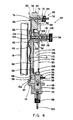
- FIG. 4 Apparatus for performing such grid spring repair in accordance with the invention is illustrated in Figs. 3 and 4.
- this apparatus generally designated with reference numeral 44, is shown attached to the outer strap 40 for use in restoring an outwardly deformed grid spring 42 to the proper side of the plane P of the strap, namely, to the side facing the fuel rod 18 extending through the grid cell partially defined by the strap 40.
- the grid spring repair apparatus 44 comprises a support frame 46, means 48 for attaching the support frame 46 to the outer grid strap to be repaired, an outer slide 50 supported on the frame 46, an inner slide 52 supported on the outer slide, and a spring-resetting mechanism 54.
- the support frame 46 of the repair apparatus 44 is formed by a plurality of interconnected top, bottom and side members 56, 58, 60 defining a generally rectangular opening 62.
- the frame 46 has also a pair of spaced-apart front and rear rails 64, 66 extending on each of the top and bottom members 56, 58 along the upper and lower sides of the opening 62.
- the pairs of rails 64, 66 together define a guide channel, indicated at 68, which extends therebetween and along the opening 62 in a direction paralleling the outer grid strap 40 and transversely across the strap spring 42 when the frame 46 is mounted to the grid 16.
- the attaching means 48 For attaching the frame 46 to the outer grid strap 40 so that the frame opening 62 is aligned with the outwardly protruding spring 42 to be repaired, the attaching means 48 includes frame attaching devices 70 mounted on the frame 46 above and below the frame opening 62. At least some of the devices 70 are adjustable to enable the frame 46 to be located and secured in a stationary position on the outer strap 40 such that the frame opening 62 is maintained in alignment with the outwardly deformed spring 42.
- the frame attaching devices 70 consist of a pair of clips 74, and a pair of screws 72 each having a head 76 and a threaded stem 78.
- One of the screws 72 extends through and is threadedly engaged in a tapped hole 80 formed in the top member 56 of the frame 46, whereas the other screw 72 has its stem 78 freely extending through and projecting from an elongate hole 82, likewise formed in the top member 56 of the frame 46, and has a knurled and internally threaded sleeve 84 threadedly disposed on the stem portion which projects from the elongate hole 82.
- the screw 72 is adjustable in its position along the elongate hole 82, allowing it to be positioned as desired, such as between two of several mixing vanes 88 (see also Fig. 2) projecting from the upper edge of the outer grid strap 40.
- the heads 76 of both screws 72 are sized to extend over and catch on upper edge portions, such as edge portion 86 (Fig. 4), of the outer grid strap 40.
- Each of the clips 74 is mounted for vertical movement along the shank 90 of a pin 92 stationarily mounted by a set screw 94 through an outwardly projecting bracket 96 on the bottom frame member 58.
- the clip 74 is held in the correct angular orientation on the pin shank 90 by a pin 95 extending through a groove 97 in the shank 90.
- the clip 74 can be set at any selected vertical position relative to the frame 46 by rotating an internally threaded knurled sleeve 98 on a threaded stem 100 extending downwardly from the pin shank 90. In this manner, the clip 74, being designed to extend under and catch on a lower edge portion 102 of the outer grid strap 40, can be drawn toward the lower edge portion 102 of the strap so as to capture it between the clip 74 and the frame 46.
- the spring reset mechanism 54 can be moved to any position within the frame opening 62 to align it with the protruding portion 104 of the grid strap spring 42. Such alignment is carried out by first moving the outer slide 50 to the desired position along the opening 62 between the frame side members 6D and then by moving the inner slide 52 to the desired position along a window-like opening 106 defined in the outer slide 50 between the top and bottom members 56, 58 of the frame 46.
- the outer slide 50 is in the form of a rectangular housing 108 having a pair of spaced front and rear vertical flanges 110, 112 on opposite lateral sides thereof.
- the flanges 110, 112 define the opening 106 in the housing 108 and also a guideway, as indicated at 114, extending between the flanges 110, 112 and along the opening 106 in a direction paralleling the outer strap spring 42 and generally orthogonal to the direction of the guide channel 68 defined by the rails 64, 66 on the support frame 14.
- the outer slide housing 108 is mounted in the guide channel 68 of the frame 46 for reciprocable sliding movement along the frame opening 62 between the lateral sides thereof permitting its opening 106 to be aligned with the outwardly protruding portion 104 of the spring 42 on the outer strap 40.
- the inner slide 52 is in the form of a rectangular plate or block which supports the spring reset mechanism 54.
- the inner slide 52 is mounted in the guideway 114 of the outer slide 50 for reciprocable sliding movement between the upper and lower ends of the opening 106 in the slide housing 108 permitting the spring reset mechanism 54 to be aligned with the protruding portion 104 of the spring 42 on the outer strap 40.
- the spring reset mechanism 54 operable to reset the protruding spring 42 to a nonprotruding position relative to the plane P of the outer strap 40, includes a cylindrical sleeve 116 which is disposed on and extends from the inner slide 52, and which has an axial bore 118 aligned with a smaller-diameter passage 120 through the inner slide 52.
- the reset mechanism 54 includes further a reset pin 122 which has a stem 124 slidably extending through the passage 120 and a larger head 126 slidably disposed in an inner portion of the axial bore 118, and it includes also an adjustable screw 128 which is threaded into a tapped outer portion of the axial bore 118 of the sleeve 116 on the inner slide 52.
- outwardly protruding outer grid strap springs 42 can be repaired by applying a substantia!ly constant load to the spring and without the necessity of applying an impact force to the fuel assembly 10.
- the particular construction of the reset pin 122 enables the latter to be moved toward the plane P of the outer strap 40 only to a predetermined extent, namely, until its head 126 bottoms out in the axial bore 118 of the sleeve 116. Therefore, a repeatable and uniform repair procedure is assured.
Landscapes
- Physics & Mathematics (AREA)
- Engineering & Computer Science (AREA)
- Plasma & Fusion (AREA)
- General Engineering & Computer Science (AREA)
- High Energy & Nuclear Physics (AREA)
- Monitoring And Testing Of Nuclear Reactors (AREA)
- Springs (AREA)
- Clamps And Clips (AREA)
- Mounting, Exchange, And Manufacturing Of Dies (AREA)
Description
- The present invention relates generally to fuel assemblies for nuclear reactors and, more particularly, to an apparatus for repairing grid springs which protrude improperly from outer straps of a grid of a nuclear fuel assembly.
- In most nuclear reactors, the reactor core is composed of a large number of elongate fuel assemblies each including a plurality of fuel rods which are held in an organized array by a plurality of grids spaced apart longitudinally of the fuel assembly and attached to elongate control-rod guide thimbles thereof. Top and bottom nozzles at opposite ends of the fuel assembly are secured to end portions of the guide thimbles extending above and below the ends of the fuel rods.
- As well known in the art, these grids are used to maintain a precise spacing between the fuel rods, to prevent rod vibration, to provide lateral support for the fuel rods, and, to some extent, to frictionally retain the rods against longitudinal movement. Conventional designs of grids include a multiplicity of inner straps interleaved in an egg-crate-like manner to define open cells which individually accept the fuel rods and control rod guide thimbles. The strap portions which define fuel-rod receiving cells are provided with resilient springs and relatively rigid protrusions (called dimples) formed out of the metal of the interleaved straps and protruding inwards of the respective cells to frictionally engage the respective fuel rods extending therethrough. Such conventional grid includes also outer straps which are joined together at their ends and have connected thereto the terminal ends of the inner straps, thereby imparting strength and rigidity to the grid. The outer straps conventionally have springs formed integral therewith from the metal thereof which springs project into the respective cells disposed along the perimeter of the grid.
- Since the, fuel rods are subjected to radiation during operation of the reactor core, it is desirable that the supporting forces imposed by the grid on the fuel rods be such that the grid will adequately support the fuel rods but will not promote lengthwise distortion thereof over the time. Moreover, since the grids are irradiated together with the fuel rods which they support, they inherently degrade with the passage of time. In particular, the metal of the straps forming the grid, hence of the springs and dimples formed therefrom, is subject to stress relaxation due to irradiation occurring over the life of a fuel assembly.
- Under these conditions, some of the grid springs formed on the outer straps of a grid occasionally become deformed in a way causing portions thereof to protrude outward from the grid, whereby the ability of such grid springs to properly support fuel rods is impaired and, in addition, the outwardly protruding spring portions create a risk of interference with the grids of neighboring fuel assemblies forming part of the same core. Therefore, it is desirable to restore any outwardly deformed grid springs to their normal positions, which conventionally is usually done by applying light impact forces with the aid of a plastic mallet and an adjustment block. This conventional technique of correcting grid spring deformation is less than ideal, not only because the application even of light impacts upon fuel assemblies during repair is undesirable, but also because this technique is lacking uniformity with regard to its results and the repair quality attainable therewith. Another tool for grid-spring repair is known from EP-A-47422, which discloses an apparatus comprising a remote controlled-grab which is introduced in the fuel grid to straighten out the deformed springs.
- If is the principal object of the invention to provide an apparatus allowing grid-spring repair to be performed without these drawbacks.
- The invention accordingly resides in a grid-spring repair apparatus for repairing a spring formed on an outer strap of a nuclear fuel-assembly grid and having a portion which abnormally protrudes outward from the strap, characterized by : (a) a support frame defining an elongate opening and having means defining guide channels along opposite longitudinal sides of the elongate opening ; (b) attaching means for attaching said support frame to said outer strap of the fuel-assembly grid in a manner such that said elongate opening extends over and across said spring on the outer strap ; (c) an outer slide which defines a window-like opening and is supported in said guide channels for reciprocable movement of the outer slide within said elongate opening in the longitudinal direction thereof so as to permit said window-like opening to be aligned with the abnormally protruding portion of the spring, said outer slide including means defining a guideway which extends along the window-like opening in a second direction substantially orthogonal with respect to said longitudinal direction ; (d) a spring resetting mechanism for restoring said abnormally protruding portion of the spring to a normal position thereof relative to the outer strap ; and (e) an inner slide which supports said spring resetting mechanism and is supported in said guideway for reciprocable movement of said inner slide within the window-like opening of the outer slide in said second direction so as to permit the spring resetting mechanism to be aligned with the abnormally protruding portion of said spring.
- This grid-spring repair apparatus of the invention is universally adaptable for use in all spring locations on all outer grid straps, and it enables abnormally protruding springs to be reset by applying thereto a constant load rather than impact forces. It also assures repeatability and uniformity of spring repairs.
- In a preferred embodiment of the invention to be described in detail later herein, the support frame of the grid-spring repair apparatus is formed of frame members interconnected so as to define said elongate opening in substantially rectangular configuration, and the means defining said guide channels are pairs of rails which are connected to the interconnected frame members and extend along the respective longitudinal sides of the elongate opening. The attaching means of the apparatus comprises several frame attaching devices which are mounted on the support frame and spaced apart in said longitudinal direction on opposite sides of the elongate opening therein, at least one of these frame attaching devices being adjustable on and relative to the mounting frame.
- The outer slide is in the form of a rectangular housing which has guideway-defining means for the inner slide formed in sides thereof extending in said second direction. The inner slide is in the form of a block supporting the spring resetting mechanism and slideably supported in said guideway.
- The spring resetting mechanism comprises a resetting pin which is slideably supported in the inner slide, and a screw which is threadedly supported in said inner slide substantially in axial alignment with the resetting pin and is operable to move the pin in a spring-restoring direction toward and against the abnormally protruding portion of the grid spring so as to urge it toward the original normal position thereof. The resetting pin has an enlarged portion which cooperates with a stop surface on the inner slide to limit movement of the resetting pin in said spring-restoring direction.
- The preferred embodiment of the invention will now be described, by way of example only with reference to the accompanying drawings, in which :
- Fig. 1 is an elevational view, partly in section, of a nuclear fuel assembly shown in vertically foreshortened form ;
- Fig. 2 is an enlarged fragmentary elevational view of an outer grid strap of one of the support grids on the fuel assembly of Fig. 1 ;
- Fig. 3 is a perspective view of the grid-spring repair apparatus embodying the invention ; and
- Fig. 4 is an enlarged sectional view of the grid-spring repair apparatus as taken along line 3-3 of Fig. 3 and showing the apparatus mounted on an outer grid strap.
- In the following description, like reference characters designate like or corresponding parts throughout the several views, and terms such as - forward « rearward", « left", « right", « upwardly « downwardly and the like are employed as words of convenience not to be construed as limiting terms.
- Referring now to the drawings, and particularly to Fig. 1, the fuel assembly shown therein and being generally designated with
numeral 10 comprises a lower end structure orbottom nozzle 12 for supporting the assembly on the lower core plate (not shown) in the core region of a reactor (not shown), control-rod guide tubes orthimbles 14 extending upward from thebottom nozzle 12,transverse support grids 16 spaced apart along theguide thimbles 14, an organized array ofelongated fuel rods 18 transversely spaced and supported by thegrids 16, aninstrumentation tube 20 in the center of the fuel assembly, and an upper end structure ortop nozzle 22 attached to the upper ends of theguide thimbles 14. Each of thefuel rods 18 containsnuclear fuel pellets 24 composed of fissile material and is sealed at its opposite ends by means ofend plugs plenum spring 30 disposed between theupper end plug 26 and thepellets 24 maintains the later firmly stacked. - The fissioning process is controlled by means of
control rods 32 reciprocally movable in theguide thimbles 14. For this purpose, thetop nozzle 22 has operatively associated therewith a rodcluster control mechanism 34 which includes an internally threadedcylindrical hub member 36 with a plurality ofradial arms 38 each of which is connected to acontrol rod 32, thecontrol mechanism 34 being operable to move thecontrol rods 32 up and down in theguide thimbles 14, all as well known in the art. - As mentioned hereinbefore, and as likewise well known in the art, each
support grid 16 consists of outer and a multitude of interleaved inner straps joined as an egg-crate-like structure with open cells through which thefuel rods 18 extend and which are defined by strap portions having resilient fuel-rod supporting springs formed out of the metal thereof. - Referring to Fig. 2, it illustrates a portion of an
outer strap 40 provided withresilient springs 42 which are formed out of the strap metal and project from the cell-defining side thereof, i. e. inwards of the cells (not shown) partially defined by theouter strap 40. As also initially explained herein, some of theseresilient springs 42 on occasion become deformed so as to protrude in the wrong direction, namely, from the outer side of the outer strap and outwards of the grid, in which event they must be restored or reset to their original and proper shape. - Apparatus for performing such grid spring repair in accordance with the invention is illustrated in Figs. 3 and 4. In Fig. 4, this apparatus, generally designated with
reference numeral 44, is shown attached to theouter strap 40 for use in restoring an outwardlydeformed grid spring 42 to the proper side of the plane P of the strap, namely, to the side facing thefuel rod 18 extending through the grid cell partially defined by thestrap 40. - Basically, the grid
spring repair apparatus 44 comprises asupport frame 46, means 48 for attaching thesupport frame 46 to the outer grid strap to be repaired, anouter slide 50 supported on theframe 46, aninner slide 52 supported on the outer slide, and a spring-resetting mechanism 54. More specifically, thesupport frame 46 of therepair apparatus 44 is formed by a plurality of interconnected top, bottom andside members rectangular opening 62. Theframe 46 has also a pair of spaced-apart front andrear rails bottom members rails opening 62 in a direction paralleling theouter grid strap 40 and transversely across thestrap spring 42 when theframe 46 is mounted to thegrid 16. - For attaching the
frame 46 to theouter grid strap 40 so that the frame opening 62 is aligned with the outwardly protrudingspring 42 to be repaired, the attachingmeans 48 includesframe attaching devices 70 mounted on theframe 46 above and below the frame opening 62. At least some of thedevices 70 are adjustable to enable theframe 46 to be located and secured in a stationary position on theouter strap 40 such that theframe opening 62 is maintained in alignment with the outwardly deformedspring 42. - Preferably, the
frame attaching devices 70 consist of a pair ofclips 74, and a pair ofscrews 72 each having ahead 76 and a threadedstem 78. One of thescrews 72 extends through and is threadedly engaged in a tappedhole 80 formed in thetop member 56 of theframe 46, whereas theother screw 72 has itsstem 78 freely extending through and projecting from anelongate hole 82, likewise formed in thetop member 56 of theframe 46, and has a knurled and internally threadedsleeve 84 threadedly disposed on the stem portion which projects from theelongate hole 82. Thus, with thesleeve 84 loosened, thescrew 72 is adjustable in its position along theelongate hole 82, allowing it to be positioned as desired, such as between two of several mixing vanes 88 (see also Fig. 2) projecting from the upper edge of theouter grid strap 40. Theheads 76 of bothscrews 72 are sized to extend over and catch on upper edge portions, such as edge portion 86 (Fig. 4), of theouter grid strap 40. Thus, by tightening thescrew 72 in the tappedhole 80 against an upper edge portion of thegrid strap 40 and tightening theknurled sleeve 84 on theother screw 72 to draw itshead 76 against the strap portion therebeneath, theframe 46 is securely positioned on thegrid strap 40. - Each of the
clips 74 is mounted for vertical movement along theshank 90 of apin 92 stationarily mounted by aset screw 94 through an outwardly projectingbracket 96 on thebottom frame member 58. Theclip 74 is held in the correct angular orientation on thepin shank 90 by apin 95 extending through agroove 97 in theshank 90. Theclip 74 can be set at any selected vertical position relative to theframe 46 by rotating an internally threadedknurled sleeve 98 on a threadedstem 100 extending downwardly from thepin shank 90. In this manner, theclip 74, being designed to extend under and catch on alower edge portion 102 of theouter grid strap 40, can be drawn toward thelower edge portion 102 of the strap so as to capture it between theclip 74 and theframe 46. - Once the
support frame 46 is attached to theouter strap 40 by means of thescrews 72 andclips 74, thespring reset mechanism 54 can be moved to any position within the frame opening 62 to align it with theprotruding portion 104 of thegrid strap spring 42. Such alignment is carried out by first moving theouter slide 50 to the desired position along theopening 62 between the frame side members 6D and then by moving theinner slide 52 to the desired position along a window-like opening 106 defined in theouter slide 50 between the top andbottom members frame 46. - The
outer slide 50 is in the form of arectangular housing 108 having a pair of spaced front and rearvertical flanges flanges opening 106 in thehousing 108 and also a guideway, as indicated at 114, extending between theflanges opening 106 in a direction paralleling theouter strap spring 42 and generally orthogonal to the direction of theguide channel 68 defined by therails support frame 14. Theouter slide housing 108 is mounted in theguide channel 68 of theframe 46 for reciprocable sliding movement along the frame opening 62 between the lateral sides thereof permitting itsopening 106 to be aligned with the outwardly protrudingportion 104 of thespring 42 on theouter strap 40. - The
inner slide 52 is in the form of a rectangular plate or block which supports thespring reset mechanism 54. Theinner slide 52 is mounted in theguideway 114 of theouter slide 50 for reciprocable sliding movement between the upper and lower ends of theopening 106 in theslide housing 108 permitting thespring reset mechanism 54 to be aligned with theprotruding portion 104 of thespring 42 on theouter strap 40. - The
spring reset mechanism 54, operable to reset the protrudingspring 42 to a nonprotruding position relative to the plane P of theouter strap 40, includes acylindrical sleeve 116 which is disposed on and extends from theinner slide 52, and which has anaxial bore 118 aligned with a smaller-diameter passage 120 through theinner slide 52. Thereset mechanism 54 includes further a reset pin 122 which has astem 124 slidably extending through thepassage 120 and alarger head 126 slidably disposed in an inner portion of theaxial bore 118, and it includes also anadjustable screw 128 which is threaded into a tapped outer portion of theaxial bore 118 of thesleeve 116 on theinner slide 52. When thescrew 128 is rotated in the appropriate direction, it moves axially against thehead 126 of the resent pin 122 to move thepin stem 124 toward and up against the protrudingportion 104 of thespring 42, as seen in Fig. 4. Then, upon further rotation of thescrew 128, the protrudingspring portion 104 is deformed so as to restore thespring 42 to its proper original position relative to the plane P of theouter grid strap 40. - Thus, it is seen that outwardly protruding outer grid strap springs 42 can be repaired by applying a substantia!ly constant load to the spring and without the necessity of applying an impact force to the
fuel assembly 10. Moreover, the particular construction of the reset pin 122 enables the latter to be moved toward the plane P of theouter strap 40 only to a predetermined extent, namely, until itshead 126 bottoms out in theaxial bore 118 of thesleeve 116. Therefore, a repeatable and uniform repair procedure is assured.
Claims (9)
Applications Claiming Priority (2)
| Application Number | Priority Date | Filing Date | Title |
|---|---|---|---|
| US772986 | 1985-09-05 | ||
| US06/772,986 US4652421A (en) | 1985-09-05 | 1985-09-05 | Outer grid strap protruding spring repair apparatus |
Publications (2)
| Publication Number | Publication Date |
|---|---|
| EP0218353A1 EP0218353A1 (en) | 1987-04-15 |
| EP0218353B1 true EP0218353B1 (en) | 1989-08-09 |
Family
ID=25096821
Family Applications (1)
| Application Number | Title | Priority Date | Filing Date |
|---|---|---|---|
| EP86306630A Expired EP0218353B1 (en) | 1985-09-05 | 1986-08-28 | Grid-spring repair apparatus |
Country Status (5)
| Country | Link |
|---|---|
| US (1) | US4652421A (en) |
| EP (1) | EP0218353B1 (en) |
| JP (1) | JPS6259897A (en) |
| KR (1) | KR870003514A (en) |
| ES (1) | ES2009137A6 (en) |
Families Citing this family (4)
| Publication number | Priority date | Publication date | Assignee | Title |
|---|---|---|---|---|
| US4832901A (en) * | 1986-05-05 | 1989-05-23 | Westinghouse Electric Corp. | Nuclear reactor fuel assembly mixing vane repair method |
| FR2641118B1 (en) * | 1988-12-28 | 1992-10-16 | Framatome Sa | |
| US6385269B1 (en) * | 2000-05-30 | 2002-05-07 | General Electric Company | Spacer spring force adjustment tool and method of adjusting the spacer spring force |
| US8416909B2 (en) * | 2009-09-29 | 2013-04-09 | Stp Nuclear Operating Company | Nuclear fuel cell repair tool |
Family Cites Families (13)
| Publication number | Priority date | Publication date | Assignee | Title |
|---|---|---|---|---|
| US1764243A (en) * | 1929-03-16 | 1930-06-17 | Arthur L Cornwell | Wheel puller |
| US1847943A (en) * | 1931-04-03 | 1932-03-01 | Griffin James | Bending and straightening tool |
| US2091844A (en) * | 1936-03-14 | 1937-08-31 | Link Belt Co | Chain pin extractor |
| US2834099A (en) * | 1953-10-08 | 1958-05-13 | Western Electric Co | Apparatus for inserting and removing pins |
| US3850795A (en) * | 1972-05-01 | 1974-11-26 | Babcock Atlantique Sa | Means for adjustable clamping skirt between pressure vessel and core |
| US3816896A (en) * | 1973-04-30 | 1974-06-18 | Raymond Lee Organization Inc | Clock repair apparatus |
| US4007544A (en) * | 1974-10-30 | 1977-02-15 | Westinghouse Electric Corporation | Constant load probe system for coordinate measurement machines |
| DE3033349A1 (en) * | 1980-09-04 | 1982-04-15 | Kraftwerk Union AG, 4330 Mülheim | ALIGNMENT TOOL FOR SPACERS FROM CORE REACTOR FUEL ELEMENTS |
| US4474730A (en) * | 1982-08-05 | 1984-10-02 | Westinghouse Electric Corp. | Nuclear fuel spacer grid |
| US4492844A (en) * | 1982-09-01 | 1985-01-08 | Westinghouse Electric Corp. | Welding plates for a fuel rod grid |
| US4539738A (en) * | 1982-09-01 | 1985-09-10 | Westinghouse Electric Corp. | Strap and vane positioning fixture for fuel rod grid and method |
| DE3242407A1 (en) * | 1982-11-16 | 1984-05-17 | Kraftwerk Union AG, 4330 Mülheim | Method for measuring the spring force of a helical compression spring which is arranged laterally on a web in a mesh of a grid-shaped spacer for a nuclear reactor fuel element, and barrel gauge for carrying out this method |
| FR2550650B1 (en) * | 1983-08-11 | 1985-11-08 | Fragema Framatome & Cogema | METHOD AND DEVICE FOR MOUNTING AND FIXING NUCLEAR FUEL ASSEMBLY GRIDS |
-
1985
- 1985-09-05 US US06/772,986 patent/US4652421A/en not_active Expired - Fee Related
-
1986
- 1986-08-28 EP EP86306630A patent/EP0218353B1/en not_active Expired
- 1986-09-04 ES ES8601631A patent/ES2009137A6/en not_active Expired
- 1986-09-05 KR KR1019860007446A patent/KR870003514A/en not_active Application Discontinuation
- 1986-09-05 JP JP61209413A patent/JPS6259897A/en active Granted
Also Published As
| Publication number | Publication date |
|---|---|
| JPH0471476B2 (en) | 1992-11-13 |
| ES2009137A6 (en) | 1989-09-01 |
| US4652421A (en) | 1987-03-24 |
| JPS6259897A (en) | 1987-03-16 |
| EP0218353A1 (en) | 1987-04-15 |
| KR870003514A (en) | 1987-04-17 |
Similar Documents
| Publication | Publication Date | Title |
|---|---|---|
| US4885127A (en) | Nuclear fuel rod support grid with attachable spring and dimple support spacers | |
| EP0384220B1 (en) | Nuclear fuel-rod support grid | |
| US7835484B2 (en) | Anti-fretting wear spacer grid with canoe-shaped spring | |
| US4357298A (en) | Nuclear fuel assembly space arrangement | |
| EP0735543B1 (en) | Method of repairing a nuclear fuel rod assembly with a damaged fuel rod and a damaged spacer | |
| US4572816A (en) | Reconstituting a nuclear reactor fuel assembly | |
| US3679546A (en) | Nuclear reactor fuel rod support grid | |
| US8483348B2 (en) | Method of providing a hold-down force upon a nuclear fuel assembly | |
| EP0218353B1 (en) | Grid-spring repair apparatus | |
| DE69208932T2 (en) | Removable springs for tube spacers in a nuclear reactor | |
| EP0797217B1 (en) | Spacer capture mechanism for non-round water rods | |
| US4587704A (en) | Method of mounting a continuous loop spring on a nuclear fuel spacer | |
| US4265010A (en) | Method and apparatus for adjusting the elevation of fuel rods in a nuclear reactor fuel assembly | |
| EP0386501A2 (en) | Improved hold-down spring clamps on fuel assembly top nozzle | |
| US4692304A (en) | Removable and reusable locking pin for top nozzle assembly and disassembly | |
| JPS63286796A (en) | Device and method of manufacturing fuel aggregate | |
| US4628581A (en) | Apparatus and method for preassembling a top nozzle subassembly for a nuclear reactor fuel assembly | |
| US4683110A (en) | Apparatus and method for consolidating spent fuel rods | |
| KR20080111409A (en) | Nuclear reactor fuel assembly grid | |
| US4678625A (en) | Method of straightening bowed irradiated fuel assemblies | |
| US11289211B2 (en) | Method of installing an external dashpot tube around a control rod guide tube in a nuclear fuel assembly | |
| DE4235685A1 (en) | METHOD FOR ASSEMBLING A NUCLEAR FUEL ELEMENT AND DEVICE THEREFOR | |
| US4747996A (en) | Apparatus and method for adjusting the elevation of fuel rods in a nuclear reactor fuel assembly | |
| US4709909A (en) | Retention strap in a grid assembly fixture | |
| US5110540A (en) | Grid for a nuclear assembly |
Legal Events
| Date | Code | Title | Description |
|---|---|---|---|
| PUAI | Public reference made under article 153(3) epc to a published international application that has entered the european phase |
Free format text: ORIGINAL CODE: 0009012 |
|
| AK | Designated contracting states |
Kind code of ref document: A1 Designated state(s): BE FR GB SE |
|
| 17P | Request for examination filed |
Effective date: 19871013 |
|
| 17Q | First examination report despatched |
Effective date: 19881212 |
|
| GRAA | (expected) grant |
Free format text: ORIGINAL CODE: 0009210 |
|
| AK | Designated contracting states |
Kind code of ref document: B1 Designated state(s): BE FR GB SE |
|
| ET | Fr: translation filed | ||
| PGFP | Annual fee paid to national office [announced via postgrant information from national office to epo] |
Ref country code: FR Payment date: 19891023 Year of fee payment: 5 |
|
| PLBE | No opposition filed within time limit |
Free format text: ORIGINAL CODE: 0009261 |
|
| STAA | Information on the status of an ep patent application or granted ep patent |
Free format text: STATUS: NO OPPOSITION FILED WITHIN TIME LIMIT |
|
| PGFP | Annual fee paid to national office [announced via postgrant information from national office to epo] |
Ref country code: SE Payment date: 19900625 Year of fee payment: 5 |
|
| PG25 | Lapsed in a contracting state [announced via postgrant information from national office to epo] |
Ref country code: FR Effective date: 19900629 |
|
| PGFP | Annual fee paid to national office [announced via postgrant information from national office to epo] |
Ref country code: BE Payment date: 19900712 Year of fee payment: 5 |
|
| 26N | No opposition filed | ||
| REG | Reference to a national code |
Ref country code: FR Ref legal event code: ST |
|
| REG | Reference to a national code |
Ref country code: FR Ref legal event code: AR |
|
| PG25 | Lapsed in a contracting state [announced via postgrant information from national office to epo] |
Ref country code: SE Effective date: 19910829 |
|
| PG25 | Lapsed in a contracting state [announced via postgrant information from national office to epo] |
Ref country code: BE Effective date: 19910831 |
|
| REG | Reference to a national code |
Ref country code: FR Ref legal event code: BR |
|
| BERE | Be: lapsed |
Owner name: WESTINGHOUSE ELECTRIC CORP. Effective date: 19910831 |
|
| EUG | Se: european patent has lapsed |
Ref document number: 86306630.4 Effective date: 19920306 |
|
| REG | Reference to a national code |
Ref country code: GB Ref legal event code: IF02 |
|
| PGFP | Annual fee paid to national office [announced via postgrant information from national office to epo] |
Ref country code: GB Payment date: 20040726 Year of fee payment: 19 |
|
| PG25 | Lapsed in a contracting state [announced via postgrant information from national office to epo] |
Ref country code: GB Free format text: LAPSE BECAUSE OF NON-PAYMENT OF DUE FEES Effective date: 20050828 |
|
| GBPC | Gb: european patent ceased through non-payment of renewal fee |
Effective date: 20050828 |