EP0218294A2 - Telephone instrument - Google Patents
Telephone instrument Download PDFInfo
- Publication number
- EP0218294A2 EP0218294A2 EP86201683A EP86201683A EP0218294A2 EP 0218294 A2 EP0218294 A2 EP 0218294A2 EP 86201683 A EP86201683 A EP 86201683A EP 86201683 A EP86201683 A EP 86201683A EP 0218294 A2 EP0218294 A2 EP 0218294A2
- Authority
- EP
- European Patent Office
- Prior art keywords
- sub
- section
- sections
- telephone instrument
- apertures
- Prior art date
- Legal status (The legal status is an assumption and is not a legal conclusion. Google has not performed a legal analysis and makes no representation as to the accuracy of the status listed.)
- Withdrawn
Links
Images

Classifications
-
- H—ELECTRICITY
- H04—ELECTRIC COMMUNICATION TECHNIQUE
- H04M—TELEPHONIC COMMUNICATION
- H04M1/00—Substation equipment, e.g. for use by subscribers
- H04M1/02—Constructional features of telephone sets
Definitions
- the invention relates to a telephone instrument having a housing constructed from a first section and a second section, the first and second sections being connected together to form a housing.
- the invention also relates to a sub-section for use in a telephone instrument.
- Telephone instruments are commonly constructed from a base section and a top section (base and top referring to a table top rather than wall mounted instrument).
- base and top referring to a table top rather than wall mounted instrument.
- the base section has items such as a tone caller mounted within it and the top section carries push buttons and perhaps a visual display and supports the handset.
- the invention provides a telephone instrument as set forth in the opening paragraph characterised in that the second section comprises a plurality of identical moulded sub-sections, the number of sub-sections being dependent on the dimensions of the first section which is formed as a single moulding.
- the first section is typically a base section of the telephone instrument and is less complex in form than the second section. Hence although a different base moulding is required for each size of instrument the tooling required is not so expensive.
- the sub-sections may comprise a first part defining a matrix of apertures suitable for locating a regular array of pushbuttons and a second part defining a single aperture which extends over a major portion of the second part.
- An array of pushbuttons may be located in the apertures of the first part, the buttons of the pushbuttons being so dimensioned that adjacent buttons cover the area between adjacent apertures with only a clearance sufficient to allow individual pushbuttons to be operated.
- a cover plate may cover locations in which no pushbutton is provided, the cover plate being located by the apertures.
- a cover plate can be located by the apertures to give a finished decorative appearance to the telephone instrument.
- the sub-sections may be mounted on a single printed circuit board.
- the printed circuit board provides, for example conductive tracks for a rubber mat keypad, key decoding circuitry and driving circuits for display devices.
- the sub-sections may be snap fitted on the printed circuit board by means of barbs on the sub-section engaging with apertures provided in the printed circuit board. This provides a structure which is sufficiently rigid for assembly and maintainance operations.
- further printed circuit boards for telephone and/or data facilities may be located in the base section.
- a further sub-assembly may be mounted in the aperture in the second part of one or more sub-sections, which sub-assembly may be a snap fit in the aperture(s).
- the sub-assembly may carry further pushbuttons and/or one or more display devices.
- the second section may comprise a further sub-section formed to locate a telephone handset.
- a sub-section may be used on a whole range of telephone instruments since most telephone instruments require a handset.
- the sub-sections may be connected to the first section by means of screws to enable the two sections to be easily separated for maintainance.
- the invention further provides a sub-section for a telephone instrument comprising a first part defining a matrix of apertures suitable for locating an array of pushbuttons and a second part defining a single aperture which extends over a major portion of the second part.
- the invention still further provides a telephone instrument including a sub-section as set forth in the preceding paragraph.
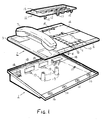
- Figure 1 shows an exploded perspective view of a telephone instrument according to the invention, the telephone instrument having a housing comprising a first section 1 in the form of a base section and a second section 2 in the form of a top section.
- the top section 2 is constructed from four sub-sections 3,4,5 and 6, sub-sections 4,5 and 6 being identical to each other and sub-section 3 being designed to locate a handset 7.
- the sub-sections 4,5 and 6 are shown in greater detail in Figures 2 and 3 and will be further described hereinafter.
- a greater or lesser number of the sub-sections 4, 5 and 6 are provided while only one sub-section 3 per instrument is used. It is, alternatively, possible to dispense with the sub-section 3 and mount the handset 7 on a hook switch projecting from the side of the base section 1.
- the sub-sections 4, 5 and 6 carry a selected arrangement of pushbuttons 8, and plates 9 and 10 which may be blank or may be provided with legends.
- a further sub-assembly 11 carrying pushbuttons 12 and a display device 13 is mountable into apertures 14 in the sub-sections 4,5 and 6 by means of barbs 15.
- the rear of the base section 1 is provided with a plurality of cut outs 18 through which cable entry may be effected.
- the cut outs may mount plugs and sockets or be covered by blanking plates depending on cable entry requirements.
- Telephone and data circuits and components may be mounted on printed circuit boards located by projections 19.
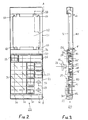
- Figure 2 shows a plan view of a sub-section 20 suitable for use as the sub-sections 4,5 and 6 of Figure 1.
- the sub-section 20 comprises a first part 21 defining a matrix of apertures 22 for locating an array of pushbuttons 23.
- the matrix of apertures 22 comprises four columns and five rows. These numbers are arbitary and may be changed depending on the application.
- the pushbuttons 23 are arranged to have a minimum spacing so that there is merely sufficient clearance between them to allow independent operation.
- cover plates 25, 26 are fitted to mask the apertures 22 and provide a finished surface to the top of the telephone instrument.
- the cover plates may be blank or may carry legends which may be produced in any convenient fashion, for example printing or engraving.
- the first part 21 and a second part 31 are separated by a bar 26 and two further bars 27 and 28 are formed at each end of the sub-section and define the extents of the first part 21 and second part 31.
- the first part 21 is also provided with a number of display devices 30 which are located next to pushbuttons adjacent to the bars 26 and 27.
- the second part 31 of the sub-section 20 defines an aperture 32 which extends over a major portion of the second part 31.
- the aperture 32 is provided with four projections 33 for co-operation with spring barbs to locate a cover plate or additional sub-assembly in the aperture 32.
- Figure 3 is a cross-sectional view of the sub-section on line A-A of Figure 2.
- the sub-section 20 is mounted on a printed circuit board 40 by means of barbs 41 which project through co-operating apertures (not shown) in the printed circuit board 40.
- the pushbutton tops 23 are located in the apertures 22 by means of plugs 42 which are a friction fit within the hollow stem 43 of the pushbutton tops 23 and which engage against shoulders 44 of the apertures 22 to prevent the pushbutton tops 23 being displaced from the apertures.
- the printed circuit board 40 is shown broken in the region of the plug 42 merely to enable the fitting of the pushbuttons to be clearly indicated and in practice the printed circuit board extends continuously.
- the plug 42 is biassed against the shoulder 44 by means of an elastomeric dome 45 which includes a conductive pill which short circuits tracks on the printed circuit board when the pushbutton is depressed. Only one dome is shown for reasons of clarity but all operative pushbuttons are provided with such domes.
- the cover plate 24 is located by means of barbs 45 which engage behind the shoulders 44 of appropriate apertures 22.
- the cover plate 25 is, of course, located in the same manner.
- the display devices 30 comprise a surface mounted light emitting diode 46 and a light guide 47, for example a perspex rod, which is in contact with the light emitting surface of the diode 46 at one end and whose other end provides the visual display at the top surface of the instrument.
- a light guide 47 for example a perspex rod
- the sub-section 20 is attached to the first or base section 1 by means of screws passing through bosses 16 and pillars 17 (Figure 1) in the base section into threaded inserts (not shown) located in the bars 26 and 27 of the sub-sections 20.
- Threaded inserts not shown located in the bars 26 and 27 of the sub-sections 20.
- Various additional or alternative methods of connecting the base and top sections would be readily apparent to those skilled in the art. For example horizontally extending lugs could be formed on the bar 28 which engage in slots provided in the rear of the base section. Alternatively adhesives could be used, particularly with simple instruments where a replacement rather than repair philosophy was employed.
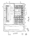
- Figure 4 shows a plan view of a telephone instrument similar to that shown in Figure 1.
- the telephone instrument shown in Figure 4 comprises a handset 107 mounted in a handset sub-section 103 and three indentical sub-sections 104, 105 and 106 which carry a plurality of pushbuttons 108, a cover plate 110 having spaces 120 for writing addresses for repertory dialling or call transfer and indicator devices 121 for indicating the address operated by a pushbutton depression or of a received call, a blank cover plate 122, and a further sub-assembly 111 carrying further pushbuttons 112 and a display unit 113.
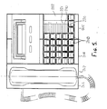
- Figure 5 shows a plan view of a telephone instrument having fewer facilities than that shown in Figure 4.
- the instrument shown in Figure 5 comprises a handset section 203 carrying a handset 207 and two identical sub-sections 204 and 205.
- the first sub-section 4 carries an array of pushbuttons 208 while the second sub-section carries a number of pushbuttons 208, a cover plate 210 which has spaces for addresses 220 and indicators 221 and a plain spacer 222.
- FIG 6 shows a plan view of a handset sub-section suitable for use in the telephone instruments shown in Figures 1, 4 and 5.
- the handset sub-section 303 comprises a rectangular plate 304 provided with two recesses 305 and 306.
- the recesses 305 and 306 are spaced and dimensioned to receive the mouth and ear pieces of the telephone handset.
- the instruments shown are designed for desk top mounting and the handset is kept in position by gravity. However, if wall mounting was desired with the handset lying substantially vertically rather than horizontally this could be achieved by appropriate design of the shape of the mouth or ear piece and the recesses.
- the recess 305 is provided with an aperture 307 through which the hook switch projects so that it can be operated by replacing the handset on the sub-section.
- a basic telephone can be provided by using a handset sub-section 303 and a sub-section 20 as shown in Figure 2. In this case only ten pushbuttons are required, though there is space for more and some additional facilities may be offered, for example for plan sets.
- the aperture 32 may then be covered by a plain cover plate which may carry a label holder for indicating the telephone number or any other information.
- An alternative arrangement providing a basic telephone instrument could use a sub-section 20 to form the complete top section with the handset being carried on a cradle or platform projecting from the side of the base unit.
Landscapes
- Engineering & Computer Science (AREA)
- Signal Processing (AREA)
- Telephone Set Structure (AREA)
- Casings For Electric Apparatus (AREA)
- Tires In General (AREA)
- Acyclic And Carbocyclic Compounds In Medicinal Compositions (AREA)
Abstract
Description
- The invention relates to a telephone instrument having a housing constructed from a first section and a second section, the first and second sections being connected together to form a housing. The invention also relates to a sub-section for use in a telephone instrument.
- Telephone instruments are commonly constructed from a base section and a top section (base and top referring to a table top rather than wall mounted instrument). Typically the base section has items such as a tone caller mounted within it and the top section carries push buttons and perhaps a visual display and supports the handset.
- There is a trend towards adding further facilities to telephone instruments, such as visual displays, repertory diallers, loudspeaking or "hands free" operation, and data transmission. Thus a family of instruments which may have a selection of these facilities may be required. This brings the problem of how to allow for the different facilities to be provided in the most economic fashion. Clearly the different instruments will require different sized housings, dependent on the number and type of facilities provided. Since the housings of the instruments are normally plastics mouldings a variety of different mouldings are required. This greatly increases the tooling costs for a range of instruments, particularly since the various options offered tends to reduce the quantity of any individual instrument type required.
- It is an object of the invention to enable the provision of a range of telephone instruments without unduly increasing the number of different mouldings required to form their housings.
- The invention provides a telephone instrument as set forth in the opening paragraph characterised in that the second section comprises a plurality of identical moulded sub-sections, the number of sub-sections being dependent on the dimensions of the first section which is formed as a single moulding.
- This enables the use of a reduced number of different mouldings with a consequent reduction in tooling costs. The first section is typically a base section of the telephone instrument and is less complex in form than the second section. Hence although a different base moulding is required for each size of instrument the tooling required is not so expensive.
- The sub-sections may comprise a first part defining a matrix of apertures suitable for locating a regular array of pushbuttons and a second part defining a single aperture which extends over a major portion of the second part.
- An array of pushbuttons may be located in the apertures of the first part, the buttons of the pushbuttons being so dimensioned that adjacent buttons cover the area between adjacent apertures with only a clearance sufficient to allow individual pushbuttons to be operated.
- This enables the top face of the instrument to present an appearance showing a complete block of buttons and if a pushbutton is not required in any position the appearance can be maintained merely by mounting a dummy button in that position.
- A cover plate may cover locations in which no pushbutton is provided, the cover plate being located by the apertures.
- Where a block of pushbuttons are not required a cover plate can be located by the apertures to give a finished decorative appearance to the telephone instrument.
- The sub-sections may be mounted on a single printed circuit board. The printed circuit board provides, for example conductive tracks for a rubber mat keypad, key decoding circuitry and driving circuits for display devices. The sub-sections may be snap fitted on the printed circuit board by means of barbs on the sub-section engaging with apertures provided in the printed circuit board. This provides a structure which is sufficiently rigid for assembly and maintainance operations. In the embodiments described hereinafter further printed circuit boards for telephone and/or data facilities may be located in the base section.
- A further sub-assembly may be mounted in the aperture in the second part of one or more sub-sections, which sub-assembly may be a snap fit in the aperture(s). The sub-assembly may carry further pushbuttons and/or one or more display devices.
- The second section may comprise a further sub-section formed to locate a telephone handset. Such a sub-section may be used on a whole range of telephone instruments since most telephone instruments require a handset.
- The sub-sections may be connected to the first section by means of screws to enable the two sections to be easily separated for maintainance.
- The invention further provides a sub-section for a telephone instrument comprising a first part defining a matrix of apertures suitable for locating an array of pushbuttons and a second part defining a single aperture which extends over a major portion of the second part.
- The invention still further provides a telephone instrument including a sub-section as set forth in the preceding paragraph.
- Embodiments of the invention will now be described, by way of example, with reference to the accompanying drawings, in which:-
- Figure 1 shows an exploded, perspective view of a telephone instrument according to the invention,
- Figure 2 shows a plan view of a sub-section for a telephone instrument according to the invention,
- Figure 3 is a cross-sectional elevation of the sub-section shown in Figure 2 the section being taken on line A-A,
- Figure 4 is a plan view of an embodiment of a telephone instruments similar to that shown in Figure 1,
- Figure 5 is a plan view of a further embodiment of a telephone instrument according to the invention, and
- Figure 6 shows a handset sub-section suitable for use in a telephone instrument as shown in Figures 1, 4 or 5.
- Figure 1 shows an exploded perspective view of a telephone instrument according to the invention, the telephone instrument having a housing comprising a first section 1 in the form of a base section and a
second section 2 in the form of a top section. Thetop section 2 is constructed from foursub-sections sub-sections sub-sections sub-sections - The
sub-sections plates 9 and 10 which may be blank or may be provided with legends. A further sub-assembly 11 carrying pushbuttons 12 and adisplay device 13 is mountable intoapertures 14 in thesub-sections barbs 15. - The rear of the base section 1 is provided with a plurality of cut
outs 18 through which cable entry may be effected. The cut outs may mount plugs and sockets or be covered by blanking plates depending on cable entry requirements. Telephone and data circuits and components may be mounted on printed circuit boards located byprojections 19. - Figure 2 shows a plan view of a
sub-section 20 suitable for use as thesub-sections sub-section 20 comprises afirst part 21 defining a matrix ofapertures 22 for locating an array ofpushbuttons 23. In this instance the matrix ofapertures 22 comprises four columns and five rows. These numbers are arbitary and may be changed depending on the application. As shown in Figure 2 thepushbuttons 23 are arranged to have a minimum spacing so that there is merely sufficient clearance between them to allow independent operation. When pushbuttons are not required in every position in the matrix ofapertures cover plates apertures 22 and provide a finished surface to the top of the telephone instrument. The cover plates may be blank or may carry legends which may be produced in any convenient fashion, for example printing or engraving. - The
first part 21 and asecond part 31 are separated by abar 26 and twofurther bars first part 21 andsecond part 31. Thefirst part 21 is also provided with a number ofdisplay devices 30 which are located next to pushbuttons adjacent to thebars - The
second part 31 of thesub-section 20 defines anaperture 32 which extends over a major portion of thesecond part 31. Theaperture 32 is provided with fourprojections 33 for co-operation with spring barbs to locate a cover plate or additional sub-assembly in theaperture 32. - Figure 3 is a cross-sectional view of the sub-section on line A-A of Figure 2. The
sub-section 20 is mounted on a printedcircuit board 40 by means ofbarbs 41 which project through co-operating apertures (not shown) in the printedcircuit board 40. Thepushbutton tops 23 are located in theapertures 22 by means ofplugs 42 which are a friction fit within thehollow stem 43 of thepushbutton tops 23 and which engage againstshoulders 44 of theapertures 22 to prevent thepushbutton tops 23 being displaced from the apertures. The printedcircuit board 40 is shown broken in the region of theplug 42 merely to enable the fitting of the pushbuttons to be clearly indicated and in practice the printed circuit board extends continuously. Theplug 42 is biassed against theshoulder 44 by means of anelastomeric dome 45 which includes a conductive pill which short circuits tracks on the printed circuit board when the pushbutton is depressed. Only one dome is shown for reasons of clarity but all operative pushbuttons are provided with such domes. Thecover plate 24 is located by means ofbarbs 45 which engage behind theshoulders 44 ofappropriate apertures 22. Thecover plate 25 is, of course, located in the same manner. - The
display devices 30 comprise a surface mountedlight emitting diode 46 and a light guide 47, for example a perspex rod, which is in contact with the light emitting surface of thediode 46 at one end and whose other end provides the visual display at the top surface of the instrument. - The
sub-section 20 is attached to the first or base section 1 by means of screws passing throughbosses 16 and pillars 17 (Figure 1) in the base section into threaded inserts (not shown) located in thebars bar 28 which engage in slots provided in the rear of the base section. Alternatively adhesives could be used, particularly with simple instruments where a replacement rather than repair philosophy was employed. - Figure 4 shows a plan view of a telephone instrument similar to that shown in Figure 1. The telephone instrument shown in Figure 4 comprises a
handset 107 mounted in ahandset sub-section 103 and threeindentical sub-sections pushbuttons 108, acover plate 110 havingspaces 120 for writing addresses for repertory dialling or call transfer andindicator devices 121 for indicating the address operated by a pushbutton depression or of a received call, ablank cover plate 122, and a further sub-assembly 111 carryingfurther pushbuttons 112 and adisplay unit 113. - Figure 5 shows a plan view of a telephone instrument having fewer facilities than that shown in Figure 4. The instrument shown in Figure 5 comprises a
handset section 203 carrying ahandset 207 and twoidentical sub-sections 204 and 205. Thefirst sub-section 4 carries an array ofpushbuttons 208 while the second sub-section carries a number ofpushbuttons 208, acover plate 210 which has spaces foraddresses 220 andindicators 221 and aplain spacer 222. - Figure 6 shows a plan view of a handset sub-section suitable for use in the telephone instruments shown in Figures 1, 4 and 5. The
handset sub-section 303 comprises arectangular plate 304 provided with tworecesses recesses recess 305 is provided with anaperture 307 through which the hook switch projects so that it can be operated by replacing the handset on the sub-section. - A basic telephone can be provided by using a
handset sub-section 303 and a sub-section 20 as shown in Figure 2. In this case only ten pushbuttons are required, though there is space for more and some additional facilities may be offered, for example for plan sets. Theaperture 32 may then be covered by a plain cover plate which may carry a label holder for indicating the telephone number or any other information. An alternative arrangement providing a basic telephone instrument could use asub-section 20 to form the complete top section with the handset being carried on a cradle or platform projecting from the side of the base unit. - Clearly many alternative arrangements using the sub-section shown in Figures 2 and 3 can be constructed, the layout of the cover plates and pushbuttons being variable to give a desired asthetic effect and to provide access to the facilities provided. Thus by using a sub-section provided with a regular array of apertures for locating pushbuttons and by arranging the buttons of adjacent pushbuttons to cover the area between the adjacent apertures a finished appearance can be given to a telephone instrument while allowing many different options to be offered using the same top sub-section. Clearly where single isolated pushbuttons are not required for a particular instrument the cover plate for that location could be constructed to have the same appearance as a pushbutton top.
Claims (11)
Applications Claiming Priority (2)
| Application Number | Priority Date | Filing Date | Title |
|---|---|---|---|
| GB858524843A GB8524843D0 (en) | 1985-10-09 | 1985-10-09 | Telephone instrument |
| GB8524843 | 1985-10-09 |
Publications (2)
| Publication Number | Publication Date |
|---|---|
| EP0218294A2 true EP0218294A2 (en) | 1987-04-15 |
| EP0218294A3 EP0218294A3 (en) | 1989-02-15 |
Family
ID=10586392
Family Applications (3)
| Application Number | Title | Priority Date | Filing Date |
|---|---|---|---|
| EP86201683A Withdrawn EP0218294A3 (en) | 1985-10-09 | 1986-09-30 | Telephone instrument |
| EP86201684A Expired - Lifetime EP0218295B1 (en) | 1985-10-09 | 1986-09-30 | Telephone instrument |
| EP86201685A Ceased EP0218296A3 (en) | 1985-10-09 | 1986-09-30 | Sub-assembly for electrical apparatus and electrical apparatus including such a sub-assembly |
Family Applications After (2)
| Application Number | Title | Priority Date | Filing Date |
|---|---|---|---|
| EP86201684A Expired - Lifetime EP0218295B1 (en) | 1985-10-09 | 1986-09-30 | Telephone instrument |
| EP86201685A Ceased EP0218296A3 (en) | 1985-10-09 | 1986-09-30 | Sub-assembly for electrical apparatus and electrical apparatus including such a sub-assembly |
Country Status (6)
| Country | Link |
|---|---|
| US (2) | US4773090A (en) |
| EP (3) | EP0218294A3 (en) |
| JP (3) | JPS6292557A (en) |
| CA (2) | CA1262194A (en) |
| DE (1) | DE3688351T2 (en) |
| GB (1) | GB8524843D0 (en) |
Cited By (1)
| Publication number | Priority date | Publication date | Assignee | Title |
|---|---|---|---|---|
| US5185791A (en) * | 1989-10-21 | 1993-02-09 | Kabushiki Kaisha Toshiba | Combination desk and wall telephone set |
Families Citing this family (17)
| Publication number | Priority date | Publication date | Assignee | Title |
|---|---|---|---|---|
| JPH01319349A (en) * | 1988-06-21 | 1989-12-25 | Matsushita Graphic Commun Syst Inc | Replacement cover of picture communication equipment and replacement method |
| US5237608A (en) * | 1989-01-30 | 1993-08-17 | Siemens Aktiengesellschaft | Telephone station having a housing with electrostatic protection |
| US5144302A (en) * | 1989-04-04 | 1992-09-01 | Apple Computer, Inc. | Modular keyboard |
| EP0713314B1 (en) * | 1990-02-15 | 2003-05-07 | Hitachi Telecom Technologies, Ltd. | Dealing board |
| DE9016975U1 (en) * | 1990-12-17 | 1991-03-07 | Deutsche Fernsprecher Gesellschaft Mbh Marburg, 3550 Marburg, De | |
| FR2690589B1 (en) * | 1992-04-24 | 1994-06-10 | Alcatel Business Systems | ELECTRONIC APPARATUS WITH ASSOCIATED KEYS AND DISPLAY. |
| EP0575767B1 (en) * | 1992-06-25 | 1998-10-14 | Siemens Business Communication Systems, Inc. (a Delaware corp.) | High visibility lightpipe in close proximity to function key |
| US6111207A (en) * | 1999-06-30 | 2000-08-29 | Hewlett-Packard Company | Kit for multi-configurable control panel design for office equipment |
| KR100359519B1 (en) * | 2000-03-16 | 2002-10-31 | 주식회사 동남 실리콘 | Front-cover for communication equipment |
| DE20021326U1 (en) * | 2000-12-16 | 2001-05-31 | Qiagen Gmbh | Device for taking samples |
| DE10140337B4 (en) * | 2001-08-16 | 2005-02-24 | Siemens Ag | Electronic terminal |
| JP2004235736A (en) * | 2003-01-28 | 2004-08-19 | Nec Infrontia Corp | Key telephone set and key telephone system |
| US7284120B2 (en) | 2003-11-17 | 2007-10-16 | Lenovo (Singapore) Pte. Ltd. | Method and system for allowing a system under test (SUT) to boot a plurality of operating systems without a need for local media |
| US7054700B2 (en) * | 2003-11-17 | 2006-05-30 | Lenovo Pte. Ltd. | Method and system for efficient order processing in a manufacturing environment |
| GB0405790D0 (en) * | 2004-03-15 | 2004-04-21 | Mitel Networks Corp | Universal microphone array stand |
| US7853926B2 (en) * | 2005-11-21 | 2010-12-14 | International Business Machines Corporation | Automated context-sensitive operating system switch |
| JP4585499B2 (en) * | 2006-08-30 | 2010-11-24 | 株式会社東芝 | Panel mounting structure, panel mounting method and telephone |
Citations (3)
| Publication number | Priority date | Publication date | Assignee | Title |
|---|---|---|---|---|
| DE1223889B (en) * | 1964-04-24 | 1966-09-01 | Siemens Ag | Telephone subscriber device |
| DE1487428A1 (en) * | 1966-05-10 | 1969-03-06 | Siemens Ag | Telephone subscriber device |
| AT297807B (en) * | 1969-03-06 | 1972-04-10 | Kapsch Telephon Telegraph | Telephone according to a modular system |
Family Cites Families (21)
| Publication number | Priority date | Publication date | Assignee | Title |
|---|---|---|---|---|
| US3521008A (en) * | 1966-10-31 | 1970-07-21 | Northern Electric Co | Telephone instrument |
| CA970086A (en) * | 1973-04-06 | 1975-06-24 | Northern Electric Company | Interconnector for telephone units |
| US3916103A (en) * | 1973-04-09 | 1975-10-28 | Northern Electric Co | Interconnector for telephone units |
| US3941951A (en) * | 1974-05-14 | 1976-03-02 | Bell Telephone Laboratories, Incorporated | Telephone stand |
| US4072840A (en) * | 1974-10-31 | 1978-02-07 | Litton Business Systems, Inc. | Removable keyboard switch |
| US4092527A (en) * | 1977-01-31 | 1978-05-30 | Texas Instruments Incorporated | Calculator with interchangeable keyset |
| CA1102767A (en) * | 1978-03-15 | 1981-06-09 | Decca Limited | Illuminated panels |
| US4291201A (en) * | 1979-04-09 | 1981-09-22 | American Telecommunications Corporation | Push-button dial assembly for telephones |
| US4284855A (en) * | 1979-08-22 | 1981-08-18 | Northern Telecom, Inc. | Base for telephone set, for alternative desk and wall mounting |
| DE3007239C2 (en) * | 1980-02-27 | 1985-02-07 | Standard Elektrik Lorenz Ag, 7000 Stuttgart | Keyboard with a large number of key sections |
| US4394545A (en) * | 1980-03-11 | 1983-07-19 | Bell Telephone Laboratories, Incorporated | Construction of a telephone instrument |
| JPS6052758B2 (en) * | 1980-09-20 | 1985-11-21 | 参天製薬株式会社 | Heterotricyclic compounds |
| US4375584A (en) * | 1980-10-06 | 1983-03-01 | Siemens Corporation | Modular telephone keyset structure |
| GB2086804B (en) * | 1980-11-04 | 1984-08-22 | Standard Telephones Cables Ltd | Keyblock assembly |
| US4385212A (en) * | 1981-10-05 | 1983-05-24 | Bell Telephone Laboratories Incorporated | Expandable communication terminal housing |
| DE3142414A1 (en) * | 1981-10-26 | 1983-05-05 | Siemens AG, 1000 Berlin und 8000 München | KEYBOARD FOR COMMUNICATION TERMINALS |
| US4481587A (en) * | 1981-12-24 | 1984-11-06 | Pitney Bowes Inc. | Apparatus for providing interchangeable keyboard functions |
| DE3211479A1 (en) * | 1982-03-29 | 1983-09-29 | Siemens AG, 1000 Berlin und 8000 München | Keypad for telephone sets |
| US4517420A (en) * | 1983-04-20 | 1985-05-14 | Northern Telecom Limited | Integral cup and hookswitch actuator for a telephone set |
| JPS6089228A (en) * | 1983-10-19 | 1985-05-20 | Matsushita Electric Ind Co Ltd | Keyboard |
| US4581495A (en) * | 1984-05-02 | 1986-04-08 | Buscom Systems Inc. | Modular telephone housing |
-
1985
- 1985-10-09 GB GB858524843A patent/GB8524843D0/en active Pending
-
1986
- 1986-09-30 EP EP86201683A patent/EP0218294A3/en not_active Withdrawn
- 1986-09-30 DE DE86201684T patent/DE3688351T2/en not_active Expired - Fee Related
- 1986-09-30 EP EP86201684A patent/EP0218295B1/en not_active Expired - Lifetime
- 1986-09-30 EP EP86201685A patent/EP0218296A3/en not_active Ceased
- 1986-10-02 CA CA000519631A patent/CA1262194A/en not_active Expired
- 1986-10-02 CA CA000519630A patent/CA1267739A/en not_active Expired
- 1986-10-07 JP JP61237266A patent/JPS6292557A/en active Pending
- 1986-10-08 JP JP61238207A patent/JPS62142447A/en active Pending
- 1986-10-09 US US06/916,918 patent/US4773090A/en not_active Expired - Fee Related
- 1986-10-09 JP JP61239387A patent/JPS62161239A/en active Pending
-
1987
- 1987-12-23 US US07/139,090 patent/US4868875A/en not_active Expired - Fee Related
Patent Citations (3)
| Publication number | Priority date | Publication date | Assignee | Title |
|---|---|---|---|---|
| DE1223889B (en) * | 1964-04-24 | 1966-09-01 | Siemens Ag | Telephone subscriber device |
| DE1487428A1 (en) * | 1966-05-10 | 1969-03-06 | Siemens Ag | Telephone subscriber device |
| AT297807B (en) * | 1969-03-06 | 1972-04-10 | Kapsch Telephon Telegraph | Telephone according to a modular system |
Non-Patent Citations (2)
| Title |
|---|
| ANT NACHRICHTENTECHNISCHE BERICHTE, no. 1, May 1984, pages 27-31, Backnang, DE; W. BRAUMANN et al.: "Der Digitale Fernsprechapparat" * |
| TELEFONBAU UND NORMALZEIT NACHRICHTEN, no. 86, 1984, pages 15-23, DE; R. LOTFI et al.: "BIGFON-ein erster Schritt der Diensteintegration in Breitbandnetzen" * |
Cited By (1)
| Publication number | Priority date | Publication date | Assignee | Title |
|---|---|---|---|---|
| US5185791A (en) * | 1989-10-21 | 1993-02-09 | Kabushiki Kaisha Toshiba | Combination desk and wall telephone set |
Also Published As
| Publication number | Publication date |
|---|---|
| EP0218296A3 (en) | 1989-02-22 |
| CA1262194A (en) | 1989-10-03 |
| EP0218295A2 (en) | 1987-04-15 |
| JPS62142447A (en) | 1987-06-25 |
| EP0218295B1 (en) | 1993-04-28 |
| JPS6292557A (en) | 1987-04-28 |
| EP0218296A2 (en) | 1987-04-15 |
| DE3688351T2 (en) | 1993-10-28 |
| CA1267739A (en) | 1990-04-10 |
| US4868875A (en) | 1989-09-19 |
| US4773090A (en) | 1988-09-20 |
| EP0218294A3 (en) | 1989-02-15 |
| EP0218295A3 (en) | 1989-02-22 |
| JPS62161239A (en) | 1987-07-17 |
| GB8524843D0 (en) | 1985-11-13 |
| DE3688351D1 (en) | 1993-06-03 |
Similar Documents
| Publication | Publication Date | Title |
|---|---|---|
| EP0218294A2 (en) | Telephone instrument | |
| EP0085482B1 (en) | Input/output device arrangements for terminals | |
| EP1360822B1 (en) | A casing | |
| US3627930A (en) | Dial-in-handset telephone assembly | |
| EP1360883B1 (en) | A casing | |
| US4375584A (en) | Modular telephone keyset structure | |
| US4790007A (en) | Telephone instrument | |
| US20030201983A1 (en) | Keymat | |
| EP0712224B1 (en) | Dealing board | |
| EP1356485B1 (en) | A casing | |
| US6850416B2 (en) | Communication panel | |
| JP2711925B2 (en) | Panel unit for dealing board operation unit | |
| IL93998A (en) | Pushbutton telephone dial keypad adaptor module | |
| JPS639169Y2 (en) | ||
| GB2371019A (en) | Mobile telephone with "V"-shaped central keys | |
| WO2002054734A1 (en) | A portable communication device | |
| EP0412045A2 (en) | Digital cross-connect assembly | |
| KR860002774Y1 (en) | A telephone supportor | |
| JPS62284551A (en) | Terminal for telephone line | |
| GB2371265A (en) | A key arrangement for a portable communication device | |
| GB2371018A (en) | A casing for a portable communication device | |
| WO2002054736A1 (en) | A portable communication device | |
| GB2371021A (en) | A portable communication device |
Legal Events
| Date | Code | Title | Description |
|---|---|---|---|
| PUAI | Public reference made under article 153(3) epc to a published international application that has entered the european phase |
Free format text: ORIGINAL CODE: 0009012 |
|
| AK | Designated contracting states |
Kind code of ref document: A2 Designated state(s): BE DE FR GB IT SE |
|
| RAP3 | Party data changed (applicant data changed or rights of an application transferred) |
Owner name: N.V. PHILIPS' GLOEILAMPENFABRIEKEN Owner name: PHILIPS ELECTRONIC AND ASSOCIATED INDUSTRIES LIMIT |
|
| PUAL | Search report despatched |
Free format text: ORIGINAL CODE: 0009013 |
|
| AK | Designated contracting states |
Kind code of ref document: A3 Designated state(s): BE DE FR GB IT SE |
|
| STAA | Information on the status of an ep patent application or granted ep patent |
Free format text: STATUS: THE APPLICATION IS DEEMED TO BE WITHDRAWN |
|
| 18D | Application deemed to be withdrawn |
Effective date: 19890816 |
|
| RIN1 | Information on inventor provided before grant (corrected) |
Inventor name: COATMAN, MICHAEL CHARLES |