EP0217622B1 - Chemical energy power plant apparatus and method - Google Patents
Chemical energy power plant apparatus and method Download PDFInfo
- Publication number
- EP0217622B1 EP0217622B1 EP86307309A EP86307309A EP0217622B1 EP 0217622 B1 EP0217622 B1 EP 0217622B1 EP 86307309 A EP86307309 A EP 86307309A EP 86307309 A EP86307309 A EP 86307309A EP 0217622 B1 EP0217622 B1 EP 0217622B1
- Authority
- EP
- European Patent Office
- Prior art keywords
- signal
- temperature
- power plant
- control
- producing
- Prior art date
- Legal status (The legal status is an assumption and is not a legal conclusion. Google has not performed a legal analysis and makes no representation as to the accuracy of the status listed.)
- Expired
Links
- 239000000126 substance Substances 0.000 title claims description 14
- 238000000034 method Methods 0.000 title claims description 8
- 239000000446 fuel Substances 0.000 claims description 69
- 238000006243 chemical reaction Methods 0.000 claims description 56
- 239000000376 reactant Substances 0.000 claims description 33
- 239000012530 fluid Substances 0.000 claims description 27
- 239000007788 liquid Substances 0.000 claims description 27
- 230000001105 regulatory effect Effects 0.000 claims description 11
- 230000003247 decreasing effect Effects 0.000 claims description 9
- 238000004891 communication Methods 0.000 claims description 2
- 230000001276 controlling effect Effects 0.000 claims description 2
- 239000003973 paint Substances 0.000 claims 1
- XLYOFNOQVPJJNP-UHFFFAOYSA-N water Substances O XLYOFNOQVPJJNP-UHFFFAOYSA-N 0.000 description 39
- 150000003839 salts Chemical class 0.000 description 16
- 230000008859 change Effects 0.000 description 12
- 230000004044 response Effects 0.000 description 12
- 239000004020 conductor Substances 0.000 description 8
- WHXSMMKQMYFTQS-UHFFFAOYSA-N Lithium Chemical compound [Li] WHXSMMKQMYFTQS-UHFFFAOYSA-N 0.000 description 7
- 230000007423 decrease Effects 0.000 description 7
- 229910052744 lithium Inorganic materials 0.000 description 7
- 241000196324 Embryophyta Species 0.000 description 6
- 230000000694 effects Effects 0.000 description 6
- 239000013529 heat transfer fluid Substances 0.000 description 6
- 238000009835 boiling Methods 0.000 description 5
- 238000004519 manufacturing process Methods 0.000 description 5
- 238000005516 engineering process Methods 0.000 description 4
- 239000000047 product Substances 0.000 description 4
- 230000001052 transient effect Effects 0.000 description 4
- 230000008901 benefit Effects 0.000 description 3
- 239000007795 chemical reaction product Substances 0.000 description 3
- 150000001875 compounds Chemical class 0.000 description 3
- 230000001419 dependent effect Effects 0.000 description 3
- 230000004927 fusion Effects 0.000 description 3
- 229910052751 metal Inorganic materials 0.000 description 3
- 239000002184 metal Substances 0.000 description 3
- 238000005496 tempering Methods 0.000 description 3
- 230000007704 transition Effects 0.000 description 3
- 244000182067 Fraxinus ornus Species 0.000 description 2
- VEXZGXHMUGYJMC-UHFFFAOYSA-N Hydrochloric acid Chemical compound Cl VEXZGXHMUGYJMC-UHFFFAOYSA-N 0.000 description 2
- MHAJPDPJQMAIIY-UHFFFAOYSA-N Hydrogen peroxide Chemical compound OO MHAJPDPJQMAIIY-UHFFFAOYSA-N 0.000 description 2
- 230000007812 deficiency Effects 0.000 description 2
- 238000010438 heat treatment Methods 0.000 description 2
- 230000000977 initiatory effect Effects 0.000 description 2
- 230000010354 integration Effects 0.000 description 2
- TVVNZBSLUREFJN-UHFFFAOYSA-N 2-(4-chlorophenyl)sulfanyl-5-nitrobenzaldehyde Chemical compound O=CC1=CC([N+](=O)[O-])=CC=C1SC1=CC=C(Cl)C=C1 TVVNZBSLUREFJN-UHFFFAOYSA-N 0.000 description 1
- NINIDFKCEFEMDL-UHFFFAOYSA-N Sulfur Chemical compound [S] NINIDFKCEFEMDL-UHFFFAOYSA-N 0.000 description 1
- 239000005864 Sulphur Substances 0.000 description 1
- 238000010521 absorption reaction Methods 0.000 description 1
- 238000013019 agitation Methods 0.000 description 1
- 230000000454 anti-cipatory effect Effects 0.000 description 1
- 230000009286 beneficial effect Effects 0.000 description 1
- 230000015572 biosynthetic process Effects 0.000 description 1
- 239000004035 construction material Substances 0.000 description 1
- 230000001934 delay Effects 0.000 description 1
- 238000005485 electric heating Methods 0.000 description 1
- -1 for example Substances 0.000 description 1
- 238000002347 injection Methods 0.000 description 1
- 239000007924 injection Substances 0.000 description 1
- 238000009413 insulation Methods 0.000 description 1
- 159000000003 magnesium salts Chemical class 0.000 description 1
- 239000000463 material Substances 0.000 description 1
- 238000002844 melting Methods 0.000 description 1
- 230000008018 melting Effects 0.000 description 1
- 230000000750 progressive effect Effects 0.000 description 1
- 230000009467 reduction Effects 0.000 description 1
- 239000007787 solid Substances 0.000 description 1
- SFZCNBIFKDRMGX-UHFFFAOYSA-N sulfur hexafluoride Chemical compound FS(F)(F)(F)(F)F SFZCNBIFKDRMGX-UHFFFAOYSA-N 0.000 description 1
- 229960000909 sulfur hexafluoride Drugs 0.000 description 1
- 239000003832 thermite Substances 0.000 description 1
- 238000011144 upstream manufacturing Methods 0.000 description 1
- 238000009834 vaporization Methods 0.000 description 1
Images

Classifications
-
- F—MECHANICAL ENGINEERING; LIGHTING; HEATING; WEAPONS; BLASTING
- F01—MACHINES OR ENGINES IN GENERAL; ENGINE PLANTS IN GENERAL; STEAM ENGINES
- F01K—STEAM ENGINE PLANTS; STEAM ACCUMULATORS; ENGINE PLANTS NOT OTHERWISE PROVIDED FOR; ENGINES USING SPECIAL WORKING FLUIDS OR CYCLES
- F01K15/00—Adaptations of plants for special use
- F01K15/02—Adaptations of plants for special use for driving vehicles, e.g. locomotives
- F01K15/04—Adaptations of plants for special use for driving vehicles, e.g. locomotives the vehicles being waterborne vessels
- F01K15/045—Control thereof
-
- F—MECHANICAL ENGINEERING; LIGHTING; HEATING; WEAPONS; BLASTING
- F01—MACHINES OR ENGINES IN GENERAL; ENGINE PLANTS IN GENERAL; STEAM ENGINES
- F01K—STEAM ENGINE PLANTS; STEAM ACCUMULATORS; ENGINE PLANTS NOT OTHERWISE PROVIDED FOR; ENGINES USING SPECIAL WORKING FLUIDS OR CYCLES
- F01K3/00—Plants characterised by the use of steam or heat accumulators, or intermediate steam heaters, therein
- F01K3/18—Plants characterised by the use of steam or heat accumulators, or intermediate steam heaters, therein having heaters
- F01K3/188—Plants characterised by the use of steam or heat accumulators, or intermediate steam heaters, therein having heaters using heat from a specified chemical reaction
Definitions
- the present invention relates to power production systems of the type which combine chemically reactive materials in a vessel or boiler/ reaction chamber to produce heat energy substantially without the evolution of exhaust gasses. More particularly, the present invention relates to apparatus in which the chemical reaction may readily be controlled or throttled so that the rate of power production may be both increased and decreased rapidly between upper and lower levels. Still more particularly, the present invention relates to a method of control and operation of power plant apparatus of the described type which is particularly directed to obtaining both a rapid response to a command for a changed power output level as well as a high operating efficiency.
- Another object of the present invention is to provide a control apparatus for such a power system for regulating the power output of the chemical reaction in such a way that its level may be rapidly changed.
- Yet another object of the resent invention is to provide a method of operating a stored-chemical. ⁇ energy power system which provides for a rapid change in the energy output level.
- Still another object of the present invention is to provide a method of operating a stored chemical energy power system in which varying levels of power output can be achieved with an improved overall system efficiency.
- a method of operating a chemical energy power plant which comprises supplying a mass of metallic fuel with a reactant which reacts exothermically with the fuel to produce heat energy, removing the energy by means of a source of working liquid communicating with a boiler tube in heat receiving relation with the fuel, to produce pressurised vapour in the boiler tube and supplying the pressurised vapour to a vapour pressure expanding motor to produce shaft power, the power output of the power plant being variable both up and down during operation by varying the rate of supply at the working liquid to the boiler tube while at the same time varying the rate of supply of the reactant to the metallic fuel thereby maintaining the mass of metallic fuel in a molten state at a substantially constant elevated temperature and simultaneously at temperating the pressurised vapour flowing to the motor by supplying working liquid thereto to maintain the pressurised vapour at a substantially constant temperature.
- the rate of reaction is regulated in dependence upon a weighted summation of working liquid flow to the motor via the boiler and the attemperation.
- the system may be controlled by the steps of providing first and second signals indicative of working liquid flow to the motor respectively via the boiler and via attemperation; providing a third signal analogous to the reaction temperature of the metallic fuel; providing control means having proportional-plus-integral control elements scaled in terms of units of reactant per unit of working liquid all divided by temperature; applying the third signal of temperature to the control means; multiplying the resultant signal from the control means having units of units of reactant per unit of working liquid by the weighted summation of the first and second signals having units of working liquid flow, to produce a command signal having units of reactant flow; and using the command signal to regulate the rate of reaction of the reactant with the metallic fuel.
- a power plant comprising: a reaction chamber for containing a reactive metallic fuel; a boiler tube in association with the reaction chamber having an inlet and an outlet, and being arranged to be in heat receiving relationship with the metallic fuel; a reactant scource for supplying an exothermically reactive reactant to the reaction chamber; a working fluid source for supplying a liquid working fluid to the inlet; and a conduit for communicating pressurised vapour of the working fluid from the outlet to a vapour pressure expanding motor; characterised by a first feed rate control valve for selectively regulating the rate of supply of working fluid to the inlet; attemperating means for communicating liquid working fluid from the source thereof to the conduit; and a second feed rate control valve for selectively regulating the rate of communication of the liquid attemperating working fluid to the conduit.
- the plant also includes first sensor for producing a first signal indicative of the power output of the said vapour pressure expanding motor, a second sensor for producing a second signal analogous to the temperature of the pressurised vapour flowing via the conduit to the expanding motor, and a third sensor for producing a third signal analogous to the temperature of metallic fuel; and control means for receiving the first, second, and third signals and for providing respective fourth, fifth, and sixth control signals individually to the first, second and third control valves for selectively variably opening and closing the valves, the control means comprising first summation means for receiving the fourth and fifth control signals and for producing seventh signal analogous to a weighted summation thereof, and multiplier means for receiving the seventh signal along with an eighth signal indicative of an error value between the third signal and a selected value (TFC) therefor and for providing the product of the seventh and eighth signals as a ninth signal productive of the sixth control signal.
- first sensor for producing a first signal indicative of the power output of the said vapour pressure expanding motor
- a second sensor for producing a second signal analog
- the plant also includes second summation means for receiving the first signal along with a command signal (Nc) of the power output level of the power plant and for producing a first difference signal therefrom, and proportional-plus-integral means for receiving the first difference signal and for supplying to a third summation means a weighted value thereof plus a time integral value thereof.
- Nc command signal
- proportional-plus-integral means for receiving the first difference signal and for supplying to a third summation means a weighted value thereof plus a time integral value thereof.
- control means may comprise time variant correction means for receiving the commanded signal of power output level and for applying to the third summation means a time variant weighted value thereof.
- the control means may further include sign maintaining squaring means for receiving from the third summation means a respective signal (x) and for producing a respective output signal having the value x times the absolute value of x, ( ⁇ .
- control means includes fourth summation means for receiving the second signal along with a selected value (TFC) therefor to produce a second error value, and proportional-plus-integral means providing to a fifth summation means a weighted value of the second error value plus a time integral value thereof.
- the control means may further include a signal inverting means for receiving from the fifth summation means a respective signal (x) and producing a signal having the value (-x).
- control means further includes sixth summation means for receiving the third signal along with the selected value (TFC) therefor to produce the error value, and proportional-plus-integral means for providing to a seventh summation means a weighted value of the error value plus a time integral value thereof, the seventh summation means producing the eighth signal.
- the control means may also include time variant delay means for effecting a time lag on variation of the seventh signal as received at the multiplier means.
- the system of the invention may incorporate control apparatus for a chemical charge power plant comprising: first means for sensing the shaft power output of the power plant and producing a respective signal; second means for sensing the temperature of a pressurised vapour supply to a vapour pressure expanding motor producing the shaft power output and for producing a respective signal; and third means for sensing the temperature analogous to the reaction temperature of a metallic fuel mass in the power plant and for producing a respective signal; characterised by first control means receiving the first signal and producing a first command of liquid working fluid supply, to a vaporiser of the power plant; second control means receiving the second signal and producing a second command of liquid working fluid supply to attemperate the pressurised vapour supply to the vapour pressure expanding motor; and third control means receiving the first command and the second command along with the third signal to produce a third command of reactant supply to the metallic fuel mass.
- the third control means further comprises time various delay means for effecting a delay in change of both the first command and the second command insofar as both effect variation in the third command.
- control apparatus for a chemical energy power plant including a reaction chamber providing a flow of pressurised working fluid vapour, a mass of molten exothermically reactive metallic fuel within said reaction chamber, a vapour pressure expanding motor receiving said flow of pressurised working fluid vapour to produce shaft power, and means for attemperating said pressurised working fluid, vapour intermediate said reaction chamber and said motor, said control apparatus comprising: first means providing a first signal indicative of a commanded power output level of said power plant; second means in association with said first means providing a second signal indicative of an actual power output level of said power plant; third means deriving from said first signal and said second signal a first error signal indicative of required change in power plant power output level; first proportional-plus-integral means providing in combination a first P-plus-I signal comprising a weighted value of said first error signal plus a time integral value thereof; corrective adder means adding to said first P-plus-I signal a time variant weighted value of said first signal to provide
- Ix ⁇ means for receiving the first output signal (x.lxl) and responsively producing a selectively valued and limited signal, f w ; first valve means for receiving the signal F w and regulating the flow rate of pressurised working fluid vapour from said reaction chamber to second therewith; fourth means providing a fourth signal indicative of a selected temperature of said pressurised working fluid vapour flow to said motor; fifth means providing a fifth signal indicative of actual temperature of said pressurised working fluid vapour flow to said motor; sixth means deriving from said fourth signal and said fifth signal a second error signal indicative of required change in temperature of said pressurised working fluid vapour flow to said motor; second proportional-plus-integral means providing in combination a second P-plus-I signal comprising a weighted value of said seocnd error signal plus a time integral value thereof; inverting means receiving said second P-plus-I signal as a value x and producing a second output having the value of negative x, (-x); means for receiving the second output signal and responsively producing a
- the summation means may include means for effecting a time delay in change of said H 2 0 signal, and may further include start-up subcontrol means for disabling said means for receiving said first output signal and latching said first proportional-plus-integral means at a time integral value of zero (0).
- the start-up subcontrol means may also include means for providing a temporary substitute signal for the signal F w designated, F WT .
- the apparatus also includes means for latching said second proportional-plus-integral means at a time integral value of zero (0).
- latching means may include means for initiating time integration upon the fifth signal attaining a determined value.
- the apparatus also includes means for latching said third proportional-plus-integral means at a time integral value of zero (0).
- These latching means may comprise means for initiating time integration upon the eighth signal attaining a certain value.
- the present invention is concerned with a stored chemical energy power apparatus comprising a reaction chamber holding a quantity of metallic fuel, menas for introducing into the reaction chamber a reactant for exothermic reaction with the fuel, heat transfer means in heat receiving relation with the fuel for heating and vapourising a pressurised heat transfer fluid communicating therethrough, means for communicating the vapourised heat transfer fluid to an expander for producing shaft power, and means intermediate of the heat transfer means and the expander for introducing a selected quantity of relatively lower enthalpy heat transfer fluid.
- the present invention thus may provide such an apparatus in which a control portion of the apparatus receives signals indicative of the commanded expander power output, and actual expander power output; of commanded temperature of the vapourised heat transfer fluid, and of actual temperature of vapourised heat transfer fluid; of commanded temperature of the reacting metallic fuel, and of actual temperature of the reacting metallic fuel; and from the foregoing producing commanded rates of supply of heat transfer fluid both to the heat transfer means, and intermediate the latter and the expander; as well as a commanded rate of supply of the reactant to the reaction chamber, which also includes an anticipatory function of the first two commanded rates of supply.
- An advantage of the present invention over conventional stored chemical energy power systems is that the temperature of steam supplied to the turbine expander is no longer directly dependent upon the temperature of which the metallic fuel reacts.
- the temperature of the boiler/ reactor may be raised to the limit of the construction material so as to minimize the formation of insulative metallic salt crust on relatively cool heat transfer surfaces.
- Another advantage of the present invention following from the independence of the temperature of the steam supplied to the expander from the temperature of the reacting metal is the independence of steam temperature during transients from the rate of supply of reactant to the reactor.
- the reaction temperature may, therefore, be maintained at a high level without the temperature of the steam supplied to the expander exceeding a desired value. It follows that because the steam temperature is more independent of the reaction temperature, the power output of the system can be varied upwardly more readily without encountering the long thermal inertia lag times common to conventional systems. Also, the chemical reaction of the fuel and reactant may take place at an advantageously high temperature.
- the superheating portion of the boiler can react directly to the increasing reactor/boiler temperature.
- the increased feed water rate further cools the subcooled portion of the boiler tube and it is believed, causes a temporary increase of salt crust on the boiler tube.
- the heat absorption capacity of the feed water is directly proportional to feed water rate of supply and is increased step-wise, while heat available from the fuel/SF 6 reaction is a time integral of SF s supply rate, the subcooled boiling transition as well as the boiling superheat transition move toward the boiler tube salt. Consequently, steam temperature to the turbine momentarily drops while the thermal inertia of the boiler/reaction is absorbing heat energy. The lower steam temperature will cause a decrease in turbine efficiency and a lower total energy output for the power plant.
- the thermal inertia of the boiler/reactor causes an undesirably slow response to a command for increase power output.
- the present invention offers a considerably different response to a commanded speed change.
- Figure 1 shows in schematic form a stored chemical energy power system according to the invention
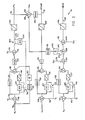
- Figure 2 depicts schematically the control apparatus portion of a power system according to the invention.
- a stored chemical energy power plant apparatus 10 The apparatus includes a reaction chamber 12 which during operation of the apparatus contains a mass 14 of molten metallic fuel.
- the fuel mass 14 may be lithium, (Li).
- a vessel 16 is provided for holding a supply of reactant 18 communicating with the fuel mass via a conduit 20 and a control valve 22.
- a pump 24 may be provided to deliver the reactant if this is needed.
- the reactant 18 may be sulphur hexafluuoride, (SF 6 ).
- a mono- tube heat exchanger 26 passes the fuel mass 14 in heat absorbing relation therewith and defines an inlet end 28 and outlet end 30.
- a pump 32 is provided for drawing water from a condenser 34 and for its delivery to the inlet 28 via a conduit 36 and a water feed rate control valve 38. From the outlet 30 steam flows to a turbine 40 via a duct 42. The turbine 30 exhausts at 44 to the condenser 34. Also, the turbine 40 is coupled by gearing 46 to the drive pump 32 and to an output shaft 48. By way of example, the output shaft 48 may drive a propeller 50. Consequently, the power plant 10 may find application, for example, to powering a life heat which may be subject to an indeterminate period of storage before its use.
- phase change fluid for example, water
- the apparatus 10 also includes a conduit 52 which extends between the feed water supply conduit 36 and the steam duct 42, and has a tempering water control valve 54.
- the latter also includes a turbine speed sensor 56 providing a signal analogous to the turbine speed (N T ) on a sensing conductor 58, a steam temperature sensor 60 providing a signal analogous to the turbine inlet steam temperature (T s ) on a signal line 62, and a reactor temperature sensor 64 providing a signal analogous to the temperature of the fuel mass 14 (T F ) on a sensing line 66.
- the valves 22, 38 and 54 also have associated therewith respective control signal lines 68, 70 and 72 whereby the opening and closing of each valve may be controlled by respective control signals supplied thereto.
- the lines 58, 62, 66, 68, 70 and 72 are all connected with a control portion 74 of the power plant apparatus 10.
- the control 74 includes a node 76 to which is supplied a signal N c analogous to a selectively variable commanded speed for the turbine 40.
- the signal N c is passed to a summing junction 78 to which the signal N T is also applied as a negative value via the sensing line 58. From the junction 78 the resulting difference signal is communicated via a proportional amplifier 80 to another summing junction 82. Also, the signal from junction 78 is conveyed via an integrator 84 and a limit circuit 86 to the junction 82.
- a corrective adder signal is obtained via a proportional amplifier 88 and a time variant buffer amplifier 90. This corrective adder signal is also applied to summing junction 82.
- elements 80-86 comprise a proportional-plus-integral controller, to -which is added an open loop anticipator circuit comprising elements 88 and 90.
- the circuit also includes a switch 92, which when closed latches the integrator 84 at a zero value.
- the resulting signal is transferred via a sign maintaining squaring circuit 94 which multiplies the signal value (x) by the absolute value of the signal value
- the resulting signal is applied positively to a summing junction 96 which also receives an offset signal OS 1 of opposite sign via a conductor 98.
- the resulting signal is conducted via a switch 100 to a limit circuit 102.
- the limit circuit supplies a control signal (F w ) via control signal line 70 to the feed water control value 38.
- a starting control sequencer (SCS) module 104 controls the switches 92 and 100 and also, when the switch 100 is open, supplies a preselected start-up valve driving signal via a conductor 106 for effecting a selected opening of the feed water control valve 38 prior to the turbine 40 attaining a selected threshold operating speed.
- SCS starting control sequencer
- the control portion 74 also includes a summing junction 108 to which is applied a signal T sc indicative of a compounded temperature of steam supplied to the turbine 40 as sensed by the sensor 60. Also applied to the junction 108 as a negative value via the sensing line 62 is the signal T s analogous to the actual steam temperature supplied to the turbine 40.
- the resulting difference signal is operated upon by a proportional-plus-integral control comprising a proportional amplifier 110, an integrator 112, an limit circuit 114, and a summing junction 116.
- the resulting signal is conveyed by an inverter 118 to a limit circuit 120, and hence to tempering water control valve 54 as a signal (ATEMP) via the control line 72.
- ATEMP tempering water control valve 54
- ATEMP tempering water control valve 54
- a summing junction 124 to which is applied a signal T FC analogous to a commanded temperature of the fuel mass 14 in the reaction chamber 12.
- the signal T F indicative of the actual temperature of the fuel mass 14 as indicated by sensor 64 is applied to the junction 124 as a negative value via the sensing line 66.
- the resulting difference signal is operated upon by a proportional-plus-integral control comprising a proportional amplifier 126, an integrator 128, a limit circuit 130, and a summing junction 132.
- the resulting signal is applied to a summing junction 134 along with an offset signal OS 2 via a conductor 136.
- the resulting signal is applied to a multiplying junction 138 along with a signal (I:H 2 0) via a conductor 140.
- the product signal from junction 138 has applied to it another offset signal OS 3 as a negative value at a summing junction 142 via a conductor 144.
- the offset product signal is applied to the reactant control valve 22 as a signal (REAC) via a limit circuit 146 and the control line 68.
- a switch 148 which is closed for start-up of the power plant 10 to latch the integrator 128 to a zero value.
- the switch 148 is responsive to a threshold value of signal T F to open during running of the power plant 10.
- the signal ZH20 is obtained from the signals F w and ATEMP via a summing junction 150 to which also is applied an offset signal OS 4 via a conductor 152, a proportional amplifier 154 effects a reduction in the level of the signal ATEMP applied to the junction 150 so that a selected response ration is established between the supply of reactant to the reactor 12 and changes in the rate of supply of feed water via the valve 38 and temperating water via the valve 54.
- the resulting summation signal from junction 150 is acted upon by a proportional amplifier 156 and a buffer amplifier 158 to produce the signal H 2 0 applied via a conductor 140 to the summing junction 138.
- the lithium fuel mass 14 is solid at ambient temperature.
- heat energy is applied to melt and liquify the lithium feel 14.
- the necessary heat energy is supplied by electric heating elements, or by ignition of a pyrotechnic chemical compound contained within the reactor 12 along with the lithium fuel mass 14.
- the reactant in this case, SF 6 is supplied via the conduit 20 and the valve 22 for exothermic reaction with the lithium fuel.
- each of the integrator latching switches 92, 122 and 148 is closed, the switch 100 is open, and the starting control sequencer (SCS) 104 provides a scheduled valve opening signal (F w ) to the feed water control valve 18. Further, during start up, the tempering water control valve 54 is maintained fully closed while the SF 6 (fuel) control valve 22 is maintained substantially fully open. To attain completion of the start-up sequence, the SCS module 104 opens the switch 92 and closes the switch 100 to transfer control of the feedwater control valve 38 to the remainder of control portion 74.
- SCS starting control sequencer
- the switches 122 and 148 are closed upon sensing of the respective selected threshold temperatures of the steam supplied to turbine 40 (T s ) and for the fuel mass 14 (T F ). Consequently, the control portion 74 provides the control signals F w , ATEMP, and REAC in response to sensed values N T . T s . and T F as well as reference values T s ⁇ and T Fc , and the power plant 10 enters the running phase of its operation. As noted earlier the remaining control variable N c of commanded turbine speed, and therefore of power plant power output, is selectively variable.
- the control signal N c is accordingly decreased.
- the control portion 74 consequently decreases the signal F w to close partially the feed water valve 38.
- the signal EH 2 0 is also adjusted downwardly at the junction 138 by the elements 150-158. The time delay effected in decreasing the supply rate of the SF 6 upon a downward change of power level allows for the decrease of water inventory which occurs within the boiler 26 when the power output is decreased, and provides energy for vaporisation of the amount of water by which the inventory is decreased.
- the temperature of the fuel mass 14 is maintained at a substantially constant level.
- the lower water inventory, substantially constant temperature level of fuel mass 14, and the continuing agitation effected by SF 6 injection substantially prevents any increase of metallic salt encrustation on the boiler tube 26 over that which may exist at higher power levels.
- the salt encrustation level on the boiler tube 26 is believed to decrease with decreasing power level because smaller portion of the boiler tube 26 is devoted to subcooled (heating of liquid water) and boiling activity.
- the decrease in salt crust on the boiler tube 26, and the required heat of fusion for the decreased salt crust is provided also by the time delay effected by the buffer amplifier 158 which delays the decrease of the SF 6 delivery rate.
- This function of the control module 74 is performed during all phases of operation of the power plant 10. Consequently, the rate of feed water supply via the valve 54 is reflected through the elements 150, 154, 156, 158 and 138 of the control module 74, and appropriately influences the feed rate of SF 6 via the valve 22.
- the resulting signal at the junction 132 has units of SFJH20.
- a multiplier having units of H 2 0 flow is applied (the H 2 0 signal). Consequently, the control signal on line 68 to SF 6 control valve 22 inherently has salts of SF 6 .
- the gain factors for circuit elements 126 and 128 are derived from the physical and heat transfer parameters of the reactor 12 including the fuel mass 14 and the boiler tube 26.
- the temperature of the fuel mass 14 is dependent upon the balance over time between the energy released within the reaction chamber 12, and energy carried away from the fuel mass by the feed water passing through the boiler tube 26 (neglecting the relatively lower enthalpy of the injected SF 6 and heat losses from chamber 12 controlled by insulation).
- the energy carried out of fuel mass 14 by the feed water is proportional directly to the rate of feed water flow and the enthalpy change effected between the inlet 28 and outlet 30.
- the enthalpy level of the feed water delivered to ° inlet 28 changes only slowly, while the enthalpy level of steam supplied to turbine 40 changes substantially not at all.
- the energy release of the fuel mass 14 is proportional to the integrated SF 6 flow. Consequently, the variation in the energy extracted from the fuel mass 14 is directly dependent by analogy upon the total steam flow through the turbine 40, and to the signal EH Z O.
- the temperature of the feel mass 14 can change only slowly because of the large thermal inertia of the fuel mass. However, it is desirable to be able to vary the power output and feed water supply rate of the power plant rapidly. Consequently, the energy balance within the fuel mass 14 may change rapidly, while the changes in temperature which reflect an energy imbalance occur much more slowly.
- the control module 74 therefore, effects a quickly reacting open loop control of the energy balance within the reaction chamber 12 via the ZH20 signal and its effect on the SF 6 delivery rate.
- a closed loop control of slower response rate inherently having the terms set out in equating 1 is affected by the use of the T F signal applied at the junction 124, and closure of this loop being effected by the energy balance and thermal mass of the fuel 14.
Landscapes
- Engineering & Computer Science (AREA)
- Chemical & Material Sciences (AREA)
- Combustion & Propulsion (AREA)
- Mechanical Engineering (AREA)
- General Engineering & Computer Science (AREA)
- Chemical Kinetics & Catalysis (AREA)
- Engine Equipment That Uses Special Cycles (AREA)
- Control Of Steam Boilers And Waste-Gas Boilers (AREA)
Applications Claiming Priority (2)
| Application Number | Priority Date | Filing Date | Title |
|---|---|---|---|
| US06/779,542 US4593528A (en) | 1985-09-24 | 1985-09-24 | Rapid transient response chemical energy power plant apparatus and method |
| US779542 | 1985-09-24 |
Publications (2)
| Publication Number | Publication Date |
|---|---|
| EP0217622A1 EP0217622A1 (en) | 1987-04-08 |
| EP0217622B1 true EP0217622B1 (en) | 1990-01-17 |
Family
ID=25116783
Family Applications (1)
| Application Number | Title | Priority Date | Filing Date |
|---|---|---|---|
| EP86307309A Expired EP0217622B1 (en) | 1985-09-24 | 1986-09-23 | Chemical energy power plant apparatus and method |
Country Status (5)
| Country | Link |
|---|---|
| US (1) | US4593528A (enExample) |
| EP (1) | EP0217622B1 (enExample) |
| JP (1) | JPS6275006A (enExample) |
| DE (1) | DE3668346D1 (enExample) |
| IL (1) | IL79617A0 (enExample) |
Families Citing this family (4)
| Publication number | Priority date | Publication date | Assignee | Title |
|---|---|---|---|---|
| US4841730A (en) * | 1987-07-02 | 1989-06-27 | Pda Engineering | Thermal actuator |
| US5086720A (en) * | 1991-01-25 | 1992-02-11 | Kahlil Gibran | Furnace for controllable combustion of thermite |
| DE102004010828B8 (de) | 2004-02-27 | 2006-03-09 | Insilico Biotechnology Gmbh | Verfahren und Mittel zum thermischen Konditionieren einer Zelle |
| US8104283B2 (en) * | 2007-06-07 | 2012-01-31 | Emerson Process Management Power & Water Solutions, Inc. | Steam temperature control in a boiler system using reheater variables |
Family Cites Families (6)
| Publication number | Priority date | Publication date | Assignee | Title |
|---|---|---|---|---|
| US3101592A (en) * | 1961-01-16 | 1963-08-27 | Thompson Ramo Wooldridge Inc | Closed power generating system |
| US3486332A (en) * | 1961-10-12 | 1969-12-30 | Trw Inc | Power plant |
| US3302401A (en) * | 1965-01-26 | 1967-02-07 | United Aircraft Corp | Underwater propulsion system |
| US3722445A (en) * | 1965-10-21 | 1973-03-27 | Us Navy | Underwater molten salt heat storage boiler |
| GB1292046A (en) * | 1969-01-24 | 1972-10-11 | Plessey Co Ltd | Improvements in or relating to power plants for use in a high-pressure environment |
| US4598552A (en) * | 1984-07-19 | 1986-07-08 | Sundstrand Corporation | Energy source for closed cycle engine |
-
1985
- 1985-09-24 US US06/779,542 patent/US4593528A/en not_active Expired - Lifetime
-
1986
- 1986-06-27 JP JP61149904A patent/JPS6275006A/ja active Granted
- 1986-08-04 IL IL79617A patent/IL79617A0/xx unknown
- 1986-09-23 DE DE8686307309T patent/DE3668346D1/de not_active Expired - Lifetime
- 1986-09-23 EP EP86307309A patent/EP0217622B1/en not_active Expired
Also Published As
| Publication number | Publication date |
|---|---|
| JPH0448922B2 (enExample) | 1992-08-10 |
| US4593528A (en) | 1986-06-10 |
| IL79617A0 (en) | 1986-11-30 |
| EP0217622A1 (en) | 1987-04-08 |
| JPS6275006A (ja) | 1987-04-06 |
| DE3668346D1 (de) | 1990-02-22 |
Similar Documents
| Publication | Publication Date | Title |
|---|---|---|
| US4297841A (en) | Control system for Cheng dual-fluid cycle engine system | |
| US4593527A (en) | Power plant | |
| US5042246A (en) | Control system for single shaft combined cycle gas and steam turbine unit | |
| US4576124A (en) | Apparatus and method for fluidly connecting a boiler into pressurized steam feed line and combined-cycle steam generator power plant embodying the same | |
| US4680927A (en) | Control system for Cheng dual-fluid cycle engine system | |
| US4698974A (en) | Internal combustion closed rankine cycle steam engine | |
| US5237816A (en) | Steam generator control systems | |
| CA1193454A (en) | Turbine high pressure bypass pressure control system | |
| EP0217622B1 (en) | Chemical energy power plant apparatus and method | |
| US4499721A (en) | Control system for Cheng dual-fluid cycle engine system | |
| EP0093724B1 (en) | Sliding pressure flash tank | |
| US4549397A (en) | Control system for Cheng dual-fluid cycle engine system | |
| US3486332A (en) | Power plant | |
| CN116291790B (zh) | 用于热管堆耦合超临界co2布雷顿循环核动力系统的启动方法 | |
| US4598552A (en) | Energy source for closed cycle engine | |
| US4277943A (en) | Method and apparatus for supplying steam to a turbine | |
| EP0147407B1 (en) | Steam generator control systems | |
| US4417438A (en) | Control system for Cheng dual-fluid cycle engine system | |
| JPS6153531B2 (enExample) | ||
| SU767372A1 (ru) | Способ регулировани тепловой нагрузки турбины с отбором пара | |
| JPH0221296A (ja) | 高速増殖炉プラントの制御方法 | |
| JP2656352B2 (ja) | 石炭ガス化発電プラント | |
| CA1221754A (en) | Steam generator control systems | |
| JPH1054545A (ja) | Lng減圧加温制御装置 | |
| JPH0228797B2 (enExample) |
Legal Events
| Date | Code | Title | Description |
|---|---|---|---|
| PUAI | Public reference made under article 153(3) epc to a published international application that has entered the european phase |
Free format text: ORIGINAL CODE: 0009012 |
|
| AK | Designated contracting states |
Kind code of ref document: A1 Designated state(s): DE FR GB IT SE |
|
| 17P | Request for examination filed |
Effective date: 19870914 |
|
| 17Q | First examination report despatched |
Effective date: 19880315 |
|
| GRAA | (expected) grant |
Free format text: ORIGINAL CODE: 0009210 |
|
| RAP1 | Party data changed (applicant data changed or rights of an application transferred) |
Owner name: ALLIED-SIGNAL INC. (A DELAWARE CORPORATION) |
|
| AK | Designated contracting states |
Kind code of ref document: B1 Designated state(s): DE FR GB IT SE |
|
| PG25 | Lapsed in a contracting state [announced via postgrant information from national office to epo] |
Ref country code: IT Free format text: LAPSE BECAUSE OF FAILURE TO SUBMIT A TRANSLATION OF THE DESCRIPTION OR TO PAY THE FEE WITHIN THE PRE;WARNING: LAPSES OF ITALIAN PATENTS WITH EFFECTIVE DATE BEFORE 2007 MAY HAVE OCCURRED AT ANY TIME BEFORE 2007. THE CORRECT EFFECTIVE DATE MAY BE DIFFERENT FROM THE ONE RECORDED.SCRIBED TIME-LIMIT Effective date: 19900117 Ref country code: SE Effective date: 19900117 Ref country code: FR Effective date: 19900117 |
|
| REF | Corresponds to: |
Ref document number: 3668346 Country of ref document: DE Date of ref document: 19900222 |
|
| EN | Fr: translation not filed | ||
| PLBE | No opposition filed within time limit |
Free format text: ORIGINAL CODE: 0009261 |
|
| STAA | Information on the status of an ep patent application or granted ep patent |
Free format text: STATUS: NO OPPOSITION FILED WITHIN TIME LIMIT |
|
| 26N | No opposition filed | ||
| PGFP | Annual fee paid to national office [announced via postgrant information from national office to epo] |
Ref country code: GB Payment date: 19950807 Year of fee payment: 10 |
|
| PGFP | Annual fee paid to national office [announced via postgrant information from national office to epo] |
Ref country code: DE Payment date: 19950928 Year of fee payment: 10 |
|
| PG25 | Lapsed in a contracting state [announced via postgrant information from national office to epo] |
Ref country code: GB Effective date: 19960923 |
|
| GBPC | Gb: european patent ceased through non-payment of renewal fee |
Effective date: 19960923 |
|
| PG25 | Lapsed in a contracting state [announced via postgrant information from national office to epo] |
Ref country code: DE Effective date: 19970603 |